 Products Home / Optical Systems / Machine Vision Camera Lenses / Bi-Telecentric Lenses for Machine Vision
Bi-Telecentric Lenses for Machine Vision
- Ideal for Machine Vision Applications
- Provide Constant Magnification Independent of Object Location
- 0.051X Magnification
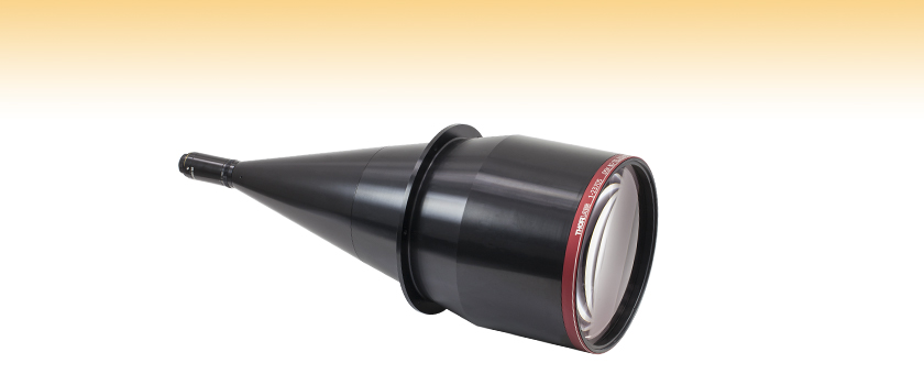
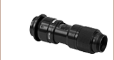
MVTC23005
0.051X Bi-Telecentric Lens

Please Wait
| Key Specificationsa | |
|---|---|
| Item # | MVTC23005b |
| Magnification | 0.051X |
| Working Distancec | 530 mm |
| Depth of Fieldd | ±260 mm |
| Field of View for 2/3" Format Sensor (Full)e |
214 mm |
| Modulation Transfer Function (MTF)f |
>51% |
| Sample Test Report | |
| Lens Mount | C-Mount (1.000"-32) |
| Lens Lengthg,h | 24.84" (630.8 mm) |
| Lens Housing Diameter at Largest Pointh |
Ø9.44" (Ø239.8 mm) |
| Weight | 13.0 kg (28.7 lbs)b |
Features
- Bi-Telecentric Lens Offers Constant Magnification Across the Depth of Field
- 0.051X Magnification
- Compatible with C-Mount Cameras with Sensors up to 2/3" Format
- Each Lens Ships with Individual Metrology and Performance Data
Thorlabs has collaborated with Navitar to design and manufacture a line of telecentric lenses for machine vision applications. With bi-telecentric lenses, the magnification in both image and object space is independent of distance (within the depth of field) or the position in the field of view. This attribute is ideal for machine vision applications: when measuring dimensions, a telecentric lens will yield the same measurement regardless of changes in object distance or position. For more details on telecentric lenses and their differences from standard lenses, please see the Telecentric Tutorial tab above.
Thorlabs offers a telecentric lens with a magnification level of 0.051X. Each lens has an adjustable iris that varies the f/#. The lens is designed for 2/3" format sensors, such as those on our scientific CCD cameras. Sensors smaller than 2/3", such as those in our other CCD and CMOS cameras, can also be used but with reduced field of view (field of view values for various sensor formats can be found on the Specs tab). The lens housing features external C-Mount (1.000"-32) threading on the image side of the lens, which is also compatible with our cameras. By using an SM1A10 thread adapter, the C-Mount can be mated to internal SM1 (1.035"-40) threads for compatibility with our Lens Tubes or other SM1-threaded mounts.
Each individual lens ships with a detailed test report showing the exact specifications and graphs for the lens; PDF samples are available in the table below. Graphs showing typical performance for field curvature, distortion, relative illumination, and Modulation Transfer Function (MTF) can be found on the Graphs tab above.
Please note that due to the size and weight of the MVTC23005, users must take care to properly mount and support this lens.
The item on this page will be retired without replacement when stock is depleted. If you require this part for line production, please contact our OEM Team.
Depth of Field
| Depth of Field for MVTC23005 0.051X Telecentric Lens |
|
|---|---|
| f/# | Depth of Field |
| 7.7 | ±260 mm |
| 11 | ±370 mm |
| 16 | ±540 mm |
| 22 | ±740 mm |
Field of View
| Field of View for MVTC23005 0.051X Telecentric Lens |
|
|---|---|
| Sensor Format | Field of View (Full) |
| 1/3" | 118 mm |
| 1/2" | 156 mm |
| 1/1.8" | 174 mm |
| 2/3" | 214 mm |
| Item # | MVTC23005 |
|---|---|
| Magnification | 0.051X |
| Magnification Error | ± 1% |
| Image Diagonal | 11 mm (2/3" Format) |
| Working Distancea | 530 mm |
| Depth of Fieldb | ±260 mm |
| Working f/#c | f/8 |
| System f/# | f/7.7 - f/22 |
| Field of View for 2/3" Format Sensor (Full)d |
214 mm |
| Telecentricity | 0 ± 0.03° |
| Max Distortion | 0 ± 0.03% |
| Modulation Transfer Function (MTF)e | >51% |
| Coherent Transfer Function (CTF)e | >63% |
| Image NA | 0.0614 |
| Object NA | 0.00315 |
| Lateral Color | R-G: <1.7 µm B-G: <0.08 µm |
| Average Transmittance | 96%f |
| Lens Mount | C-Mount (1.000"-32) |
| Lens Lengthg,h | 24.84" (630.8 mm) |
| Lens Housing Diameter at Largest Pointh |
Ø9.44" (Ø239.8 mm) |
| Lens Weight | 13.0 kg (28.7 lbs) |
Click on the icons in the table below to see performance graphs for the telecentric lens. These graphs show the theoretically calculated modeling results from Zemax for the field curvature, distortion, relative illumination, and Modulation Transfer Function (MTF) for our telecentric lenses. Each lens ships with an individual test data sheet that contains test data for the lens, including plots of the MTF and distortion.
| Item # | Lens Magnification | Field Curvature | Distortion | Relative Illumination @ 588 nm |
MTF | ||
|---|---|---|---|---|---|---|---|
| MVTC23005 | 0.051X |  |
 |
 |
f/7.7 | f/11 | f/22 |
 |
 |
 |
|||||
Telecentric Lenses
Telecentric lenses are designed to have a constant magnification regardless of the object's distance or location in the field of view. This attribute is ideal for many machine vision measurement applications, as measurements of an object's dimension will be independent of where it is located.
Types of Telecentric Lenses
In order to achieve a telecentric lens design, all of the chief rays (rays from an off-axis point that pass through the center of the aperture stop) have to be parallel to the optical axis in either image space or object space, or both. For an object space telecentric lens, the chief rays will be parallel to the optic axis on the object's side of the lens (object space). This is accomplished by setting the aperture stop at the front focal plane of the lens, which results in an entrance pupil at infinity. Since chief rays are directed towards the center of the entrance pupil, the chief rays on the object side of the lens will be parallel to the optical axis. An example of an object space telecentric lens is shown in Figure 1.

Figure 1: A ray trace through an idealized object space telecentric lens system. Note that the chief rays (the center ray of each color) is parallel to the optical axis in object space, but in image space, the chief rays form an angle with the optical axis.
For an image space telecentric lens, the chief rays will be parallel to the optical axis on the image's side of the lens (image space). This is accomplished by setting the aperture stop at the back focal plane of the lens, which results in an exit pupil at infinity. Since the chief rays must pass through the center of the exit pupil, the chief rays on the image side of the lens must be parallel to the optical axis. For a double telecentric, or bi-telecentric, lens, the front and back focal planes are made to overlap so that the aperture stop is located where both the entrance and exit pupils are at infinity. In a bi-telecentric lens, neither the image or object location will affect the magnification. Thorlabs' telecentric lenses are all bi-telecentric designs. Figure 2 shows an example ray trace through a telecentric lens and illustrates how the chief rays pass through the system.

Figure 2: A ray trace through an idealized bi-telecentric lens system. Note that the chief rays (the center ray of each color) is parallel to the optical axis in both image and object space, which means that the magnification will remain constant regardless of object distance.
Conventional Lenses
In conventional lenses, the entrance and exit pupils are not located at infinity, so the chief rays will not be parallel to the optical axis. In this case, the magnification of the object depends on its distance from the lens and its position in the field of view. Figure 2 shows an example ray trace through a conventional camera lens; notice how the chief rays are angled with respect to the optical axis in both image and object space. Note that both Figures 2 and 3 feature the same lens design; only the aperture stop location was varied to shift the telecentric system to a non-telecentric one.

Figure 3: A ray trace through an idealized conventional camera lens system. Note that the chief rays (the center ray of each color) is not parallel to the optic axis in both image and object space, which means that the magnification will vary with object distance.
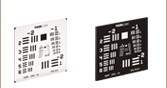
Example Images
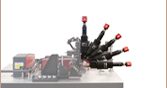
Figures 4 and 5 show photographs taken with a telecentric lens and a standard camera lens, respectively. With the telecentric imaging system, the height of the two screws appears to be the same, even though the object planes are separated by approximately 45 mm along the optical axis. With the conventional imaging system, the two screws appear to be different heights, and therefore a machine vision system based on this lens will lead to incorrect dimensional measurements.

Click to Enlarge
Figure 4: An image of two identical 8-32 cap screws imaged with our previous generation MVTC23013 0.128X Telecentric Lens. Although the screws appear to be the same size and in the same object plane, they are actually separated by a distance of approximately 45 mm along the optical axis.

Click to Enlarge
Figure 5: The same two screws photographed with our MVL7000 conventional zoom lens. In this image, the perspective error due to the separation of the screws would lead to incorrect height measurements.
| Posted Comments: | |
user
(posted 2020-11-10 08:25:43.26) Hello, I would like to use this lens in deep UV wavelengths. You specify >96% down to 460 nm. Do you have any information over the transmission below that? What material are the lenses made of and is there any coatings? YLohia
(posted 2020-11-10 11:59:14.0) Hello, thank you for contacting Thorlabs. The transmission of this lens falls down to ~15% at 350 nm. I have reached out to you directly with some data. user
(posted 2019-06-19 02:30:54.85) Hi,I have some question about bi-telecentric lens.
Bi-telecentric means object and image space also telecentric.For MVTC23005 bi-telecentric lens,can I use it in reverse?
like put a LED pattern at back focal point(original image plane),and project the LED pattern image to a sreen at original object plane.
What any problem will happen when I use bi-telecentric lens in reverse?
thank you! llamb
(posted 2019-06-25 10:27:24.0) Thank you for your feedback. While the MVTC23005 can in principle be used in reverse, this may not be very suitable for your application. The image NA is 0.0614, which means only a small amount of LED light would be collected, assuming the LED has a rather large NA. Additionally, the working distance is 530 mm, which can limit your screen's location range. I have reached out to you directly to discuss your application further. lylaana
(posted 2017-06-16 10:36:13.423) Hi, I'am tying to build a simple imaging system for QR code scanner. I'am wondering if this bi-telecentric lens is enough for a CMOS image sensor. Will extra lens be needed?
Thank you very much! tfrisch
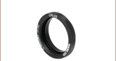
(posted 2017-06-27 10:09:12.0) Hello, thank you for contacting Thorlabs. These lenses are all C-mount threaded which is a common thread for a CMOS camera, and they can be used directly with a C-mount camera. Some CMOS cameras are CS-mount which uses the same thread, but a shorter flange focal distance (the distance from the flange of the lens to the sensor). In those cases, an adapter like CML05 can be used. I will reach out to you directly to discuss your application. |