 Products Home
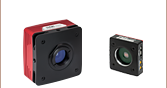
High-Resolution USB CCD Cameras
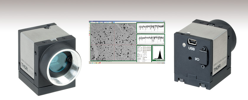
- Pixel Resolution of 1024 x 768 or 1280 x 1024
- 30 fps or 15 fps Models Available
- USB 2.0 Interface
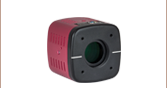
DCU223M
GUI and Software Package Included


Please Wait
| Item # | DCU223 | DCU224 |
|---|---|---|
| Resolution | 1024 x 768 Pixels | 1280 x 1024 Pixels |
| Pixel Clock Rangea | 5-30 MHz | |
| Binning | Verticalb | |
| AOI | Horizontal, Verticalb | |
| Frame Rate at 320 x 240 Pixel (Cif) | 78 fps | 38 fps |
Features
- 1024 x 768 or 1280 x 1024 Pixel Color and B&W Versions Available
- 1/3" or 1/2" Image Sensor with Square Pixels
- Choose from 30 fps or 15 fps (Full Frame Mode)
- C-Mount Lens Mount for use with our Standard C-Mount Camera Lenses and High-Magnification Zoom Lenses
- Global Shutter
- Universal Trigger Input
- ThorCam™ Software for Windows® 7 and 10 Operating Systems
- SDK and Programming Interfaces Provide Support for:
- C, C++, C#, and Visual Basic .NET APIs
- LabVIEW, MATLAB, and µManager Third-Party Software
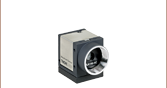
Sensors and Functionality
These ultra compact, lightweight CCD cameras feature USB connections, making them extremely versatile for a wide range of applications including industrial automation, quality control, medical imaging, microscopy, and security technology. The DCU223 models are equipped with a high-quality SONY 1/3" CCD sensor with XGA resolution (1024 x 768) and provide a full frame repetition rate of 30 fps. The DCU224 models have a 1/2" CCD sensor with SXGA resolution (1280 x 1024) and provide a full frame repetition rate of 15 fps.
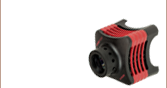
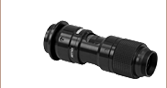
SM1 Thread Compatibility
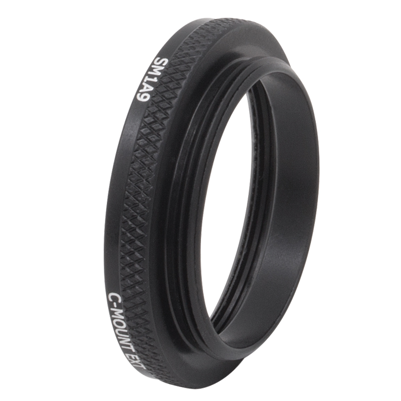
 Compatibility of the CCD Camera with Thorlabs' SM1 Internal or External Threadings via the Included SM1 (1.035"-40) Adapters. Replacement adapters are shown below.
For all models, higher frame rates can be achieved by using the Area of Interest (AOI) or Binning functions; the former increases the frame rate by only reading a selected area of the sensor, whereas the latter increases the frame rate by combining pixel readings before transferring them to the PC, but in this case, image resolution is sacrificed. The computer can communicate digitally with the camera through the USB 2.0 interface, thus enabling the user to transmit images and control camera settings seamlessly.
Software
Each CCD camera comes with ThorCam, our Windows-compatible software package on CD. In addition, the cameras are supported by an extensive software development kit. Standard drivers like Direct Show (WDM), Active X, and TWAIN are provided. In addition, over 20 demo programs (including source code) are supplied. A USB cable for connecting the camera to a PC is also included.
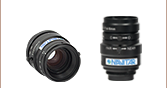
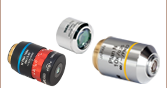
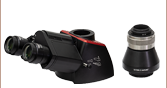
Lenses
The DCU223 CCD cameras are fully compatible with our standard C-Mount Camera Lenses and High-Magnification Zoom Lenses, which are sold separately. Our standard lenses include fixed focal lengths of 3.5 mm - 75 mm with maximum apertures of up to f/0.95, as well as an 18 - 108 mm f/2.5 zoom lens. Our high-magnification zoom lenses are a modular system that features magnification from 0.07 - 28.
Included Mounting Adapters
Each CCD camera includes two thread adapters: one external C-Mount to internal SM1 (1.035"-40) and one external C-Mount to external SM1. The C-Mount threading of the CCD camera can be easily connected to components with Thorlabs' standard SM1 thread via one of the two included SM1 adapters, as shown in the photo to the right. Additional or replacement adapters may be purchased below. A mounting adapter plate is also provided with the CCD camera; by using the included M4 x 10 mm or 8-32 x 3/4" cap screw, the camera can be threaded onto Thorlabs' TR series Ø1/2" posts. Every unit also ships with four M3 x 6 mm screws for mounting the adapter plate to the camera.
Trigger Option
The optional CAB-DCU-T1 and CAB-DCU-T2 cables can replace the standard USB connection while also enabling the use of the additional trigger input and output ports of these cameras. The exposure and readout/transfer events of the camera can be initiated via the input trigger; external events like strobe lights can be triggered by the camera through the output trigger. The trigger configuration, i.e. the source of the input trigger and the timing for the output trigger, can be set through the provided software or the LabVIEW drivers. Please click here for more details about the cables and the ordering information.
| Item # | DCU223M | DCU223C | DCU224M | DCU224C |
|---|---|---|---|---|
| Sensor | ||||
| Sensor Type | CCD | |||
| Exposure Mode | Electronic Global Shutter | |||
| Read Out Mode | Progressive Scan | |||
| Resolution | 1024 x 768 Pixels | 1280 x 1024 Pixels | ||
| Optical Sensor Class | 1/3" | 1/2" | ||
| Exact Sensitive Area | 4.76 mm x 3.57 mm | 5.95 mm x 4.76 mm | ||
| Exact Optical Sensor Dimension (Diagonal) | 6.0 mm (0.24") | 7.6 mm (0.30") | ||
| Pixel Size | 4.65 µm x 4.65 µm | |||
| Sensor Name | Sony ICX204AL | Sony ICX204AK | Sony ICX205AL | Sony ICX205AK |
| A/D Converter Resolution | 8 Bit | |||
| S/N Ratio | ≥38 dB | |||
| Frame Rates | ||||
| Pixel Clock Rangea (Allowed/Recommended) | 5 - 30 MHz/10 - 20 MHz | |||
| Frame Rate, Freerun Modeb | 30 fps | 15 fps | ||
| Frame Rate, Trigger Mode, 1 ms Exposure Timeb |
28.7 fps | 17 fps | ||
| Exposure Time in Freerun Mode | 30 µsb - 773 msc | 66 µsb - 1360 msc | ||
| Exposure Time in Trigger Mode | 30 µsb- 10 minc | 66 µsb - 10 minc | ||
| Binning | Verticald | |||
| Method | V: Monochrome Binning, Additive | |||
| Factor, Maximum Resolution, Frame Rate | 2x, 1024 x 384 Pixel, 53 fps | 2x, 1280 x 512 Pixel, 23 fps | ||
| Factor, Maximum Resolution, Frame Rate | 4x, 1024 x 192 Pixel, 85 fps | 4x, 1280 x 256 Pixel, 31 fps | ||
| Subsampling | - | |||
| AOI | Horizontal, Vertical d | |||
| Frame Rate at 320 x 240 Pixel (Cif) | 78 fps | 38 fps | ||
| Absolute Image Width, Step Width | 16 - 1024 Pixel, 4 | 16 - 1280 Pixel, 4 | ||
| Absolute Image Height, Step Width | 120 - 768 Pixels, 1 | 120 - 768 Pixels, 2 | 120 - 1024 Pixels, 1 | 120 - 1024 Pixels, 2 |
| Position Raster Horizontal | 1 | 2 | 1 | 2 |
| Position Raster Vertical | 1 | 2 | 1 | 2 |
| Gain | ||||
| Monochrome Model | 10.47X (Master) | 7.59X/4X (Master/RGB) | 13.66X (Master) | 8.9X/4.0X (Master/RGB) |
| Offset Control, Mode | Auto, Manual, Additive | |||
| Gain Boost | 2x | n/a | 2x | n/a |
| Trigger | ||||
| Hardware Trigger | Asynchronous | |||
| Trigger Delay With Rising Edge, Jitter | 39.5 µs ± 2.6 µs | 39.9 µs ± 2.5 µs | ||
| Trigger Delay With Falling Edge, Jitter | 57.9 µs ± 2.6 µs | 57.7 µs ± 2.5 µs | ||
| Additive Trigger Delay To the Sensor | 15 µs - 4 s | |||
| Sensor Delay To the Exposure Start | <100 µsb | |||
| Trigger Low Levele | 0 V Min, 2 V Max | |||
| Trigger High Levele | 5 V Min, 24 V Max | |||
| Power Consumption | 1.0 - 1.7 W | 1.1 - 2.1 W | ||
| Housing | ||||
| Protective Window, Removable | Uncoated Glass (D263) |
IR Filter D263 with HQ coating |
Uncoated Glass (D263) |
IR Filter D263 with HQ coating |
| Interface | USB 2.0 | |||
| Power Supply | 1.7 W, via USB | 1.1 to 2.1 W | ||
| Operating Temperature | 32 to 122 °F (0 to 50 °C) | |||
| Security Labels | CE, FCC, Class A | |||
| Dimention (H x W x D) | 1.59" x 1.26" x 1.35" (40.35 mm x 32 mm x 34.4 mm) | |||
| Weight | 0.21 lbs (96 g) | |||
| Lens Connector | C-Mount | |||
| Included Adapters | External C-Mount to External SM1 (Replacement Item # SM1A39) and External C-Mount to Internal SM1 (Replacement Item # SM1A9 or SM1A9TS) |
|||
Pixel Sensitivity of the CCD Camera


Pixel sensitivity versus wavelength plots are shown at the right for the monochromatic and color versions of these CCD cameras. The color model incorporates a removable IR filter that blocks the spectral region marked by the pink background. For this model, the popular Bayer color filter array is used to acquire digital color images. The filter is based on the repeating 2 x 2 pattern shown to the left; half of the total number of pixels are green (G), and the remaining pixels are equally divided between red (R) and blue (B).
Due to this arrangement, each pixel is only sensitive to one color, and as a result, the overall sensitivity of the color image is three times lower than that achievable with a monochromatic sensor. Thus, B&W CCD cameras are preferred in low-light situations. Even though only one third of the color information is obtained at each pixel, a full-color image can be achieved through the use of various demosaicing algorithms that interpolate a set of red, green, and blue B G B G values at each point.
ThorCam™

Click to Enlarge
ThorCam Graphical User Interface (GUI)
Software
Version 3.5.1
Click the button below to visit the ThorCam software page.
ThorCam is a powerful image acquisition software package that is designed for use with our cameras on 32- and 64-bit Windows® 7 or 10 systems. This intuitive, easy-to-use graphical interface provides camera control as well as the ability to acquire and play back images. Single image capture and image sequences are supported. Application programming interfaces (APIs) and a software development kit (SDK) are included for the development of custom applications by OEMs and developers. The SDK provides easy integration with a wide variety of programming languages, such as C, C++, C#, and Visual Basic .NET. Support for third-party software packages, such as LabVIEW, MATLAB, and µManager* is available.
*µManager control of Zelux and 1.3 MP Kiralux cameras is not currently supported. When controlling the Kiralux Polarization-Sensitive Camera using µManager, only intensity images can be taken; the ThorCam software is required to produce images with polarization information.
| Posted Comments: | |
Jorge Flores
(posted 2023-08-29 15:04:37.88) I have this CCD camera, model DCU224C, but the infrared-blocking filter that is in from of CCD sensor is damaged, could you quote me? Markus Rambach
(posted 2020-06-29 01:42:49.29) Hi there,
is there. a SDK for Python so I can integrate the camera with the rest of our software?
Thanks
Markus YLohia
(posted 2020-06-29 11:31:58.0) Hello Markus, thank you for contacting Thorlabs. Unfortunately, we do not offer a Python SDK or support Python integration for the DCU224M camera. However, we do offer C++ example code for the C dll's, which would allow you to use the same methods in the CTypes Python package. Jerri Drazkiewicz
(posted 2020-04-24 10:09:15.577) we need to produce a trigger signal from a PC, and we want to connect it to the camera, which is a DCU224M, which cable T1 or T2 is the best for this application? please advise. YLohia
(posted 2020-04-24 02:20:05.0) Thank you for contacting Thorlabs. The CAB-DCU-T1 allows for both input and output communication to the camera, while the CAB-DCU-T2 allows only for the input. For your application, either of these cables will work. If you also plan on sending a trigger out from the camera, then CAB-DCU-T1 is the correct option. Min Liang
(posted 2019-03-13 16:27:13.45) 需要能覆盖波长范围1000-2000nm的COMS或CCD相机, 用于半导体激光器光斑光强分布的观察和分析,请推荐合适的型号;如果没有完全满足的,也请把接近的型号发给我参考, 谢谢! YLohia
(posted 2019-04-08 10:54:29.0) Hello, our Tech Support team in China has reached out to you directly regarding this request. 544738560
(posted 2019-01-07 15:56:51.543) How much power light can not damage this camera? llamb
(posted 2019-01-10 07:18:28.0) Thank you for contacting Thorlabs. The damage threshold of these cameras will be dependent on a number of factors including the quantum efficiency at the given wavelength, the gain settings of the camera, and the bit depth. The damage threshold will be higher than the saturation, so it is typically easy to avoid damage just by looking for saturated pixels. I will reach out to you directly to discuss your application. etienne.brasselet
(posted 2018-11-12 10:54:27.183) Hello,
i would like to know whether I can detect some signal at 1064nm with camera DCU223C, even though the sensitivity will be very low? I would like to know it before purchasing optics at 1064nm dedicated to a preliminary study...
Thanks. YLohia
(posted 2018-11-13 09:51:29.0) Hello, thank you for contacting Thorlabs. The DCU223C has two filters: an IR blocking filter and a Bayer filter. The IR blocking filter is removable while the Bayer filter isn't. Leaving the Bayer filter makes it unsuitable for use with 1064nm. That being said, this all depends on what your requirements are and what beam parameters (angle of incidence, beam diameter, power) you are working with. We recommend looking into the DCC3240N, which is designed for the NIR range. Lucchij5
(posted 2018-07-05 11:43:13.297) Hello. I'm working on using a CCD to try to capture plasma images from laser ablation. I have a photodiode on a side path of the laser, which sends a trigger to a signal delay generator, which then triggers the CCD. With the laser at 10 Hz I am able to acquire at 10 FPS. However, I end up dropping around 30% of my frames. My bigger issue is that even setting a large delay (5ms) on the delay generator still shows plasma, even though it should only last a few microseconds. My PI believes that our jitter is high or that we are overexposing, despite the exposure time being set to minimum.
Another problem is sometimes increasing delays caused the plasma image to travel upwards in the frame, my PI also believes is an electronic issue with the camera. YLohia
(posted 2018-09-17 09:35:44.0) Response from Yashasvi at Thorlabs USA: Hello, thank you for contacting Thorlabs. Based on our direct correspondence regarding the troubleshooting of this issue it appears the plasma optical intensity is extremely high, resulting not only in saturation but blooming; a super-saturation phenomenon. As a result, you will need some level of ND filtering. The extreme intensity can cause all manner of non-ideal effects (possibly the perplexing insensitivity to the delay) and potential for spurious signal (e.g. blooming, or crosstalk due to light-piping in the chip, or photodiode “lag”) to be registered even if the illumination event is occurring prior to the actual camera exposure interval.
Given that the object creates a brief pulse of illumination (apparently a few microseconds), well below the exposure granularity of the camera, one can visualize this illumination pulse occurring within an exposure “window,” the position of which is determined by your delay generator and the width of which is determined by the camera exposure time. Then, once the pulse is properly positioned within the exposure window, the width of the window (exposure time) makes no difference (nor would a relatively small amount of jitter).
Our recommendation is that the exposure time should be set to at least 150 microseconds (arbitrarily creating some timing margin inside the camera). You will then have to experiment with ND filters until you find a combination that gets you below saturation, then adjust your delay to ensure maximizing the signal, and then observe that increasing the exposure time has little or no effect. Please note that the camera has its own fixed, minimum delay in the manual.
Assuming the photodiode detector’s trigger output delay is less than that of the camera (it does seem to be the case from the data sheet), then adding delay to the trigger signal to the camera will not be helpful. You may have a fundamental problem of the event occurring before the exposure. It is possible that the reason you are seeing anything at all is because the sensor is being overwhelmed even though the camera hasn’t even begun its exposure. If this is the case, once you start the ND process and getting away from blooming, the signal will effectively disappear. We recommend that you diagram and characterize the relative delays to avoid getting caught up in a loop. yin.xiao
(posted 2018-05-04 05:18:48.33) Dear Sir/Madam,
1. For DCU224M, the labview software can connect the device, but the camera cannot capture any image.
2. When we want to use matlab to control this device, the matlab program given by your website cannot find the device.
Any help will be greeted! llamb
(posted 2018-05-24 10:18:19.0) Hello, thank you for contacting Thorlabs. The issues described are often caused by an incompatibility in softwares and operating systems, using 32-bit Thorcam or Matlab for a 64-bit OS for example. I have reached out to you directly to troubleshoot further. hillier
(posted 2018-01-19 08:58:52.733) How do I perform a software trigger on the DCU223C camera? I can't figure out how to do it with the Thorlabs Camera software, although the manual suggests that I can. I need to collect images with a longer exposure time than the maximum allowed with the free-run setting. YLohia
(posted 2018-05-01 09:18:08.0) Hello, thank you for contacting Thorlabs. I have reached out to you directly to find out more about your application. One thing to note is that the only DCU223C supports ~1 sec max exposure time. LO0002JI
(posted 2017-07-13 15:15:28.977) Dear Sir/Madam,
Can you advise the allowable power density applied to the CCD?
MJ tfrisch
(posted 2017-08-17 11:10:45.0) Hello, thank you for contacting Thorlabs. The saturation power will be dependent on a number of factors including the quantum efficiency at the given wavelength, the gain settings of the camera, and the bit depth. The damage threshold will be higher than the saturation, so it is typically easy to avoid damage just by looking for saturated pixels. I will reach out to you directly to discuss your application. user
(posted 2017-03-14 14:34:37.22) Hello, I intend to use a DCU224M camera with coherent light, so I would like to remove the cover glass (in contact with the chip) in order to avoid interferences. Though, the names are confusing :
a-Specs Tab : "Protective Window, Removable -> Uncoated Glass (D263)"
b-Manual 2016 p465 : " All sensors have a D263 type cover glass "
Could you please confirm that the "removable protective window" is indeed the "Cover glass" and not the "Filter" (which can also be D263-type and can also be removed) ?
Since tfrisch
(posted 2017-03-15 02:52:23.0) Hello, thank you for contacting Thorlabs. In addition to the removable window in the camera, the DCU224M uses the Sony ICX205AL sensor which has a 0.75mm thick window which is not removable. Please contact TechSupport@Thorlabs.com to discuss details or the possibility of a sensor with no window. madhan2388
(posted 2017-03-09 17:30:54.99) Greetings!
In our Lab we use Thorlab CCD. the front portion of the blue colour glass has a blur finishing. We use nearly 5 CCD's this has happened on all. Though we are using it with much care without touching the front glass. Can I know the reason ? and what is the possible way to clear blur finish?
Sincerely,
Paul Madhan. jlow
(posted 2017-03-09 09:56:17.0) Response from Jeremy at Thorlabs: This is generally due to dust or external contamination. To clean the filter, use a wipe to remove dust particles in a single sweep over the edge of the filter glass. Please refer to page 469 of the manual (https://www.thorlabs.com/_sd.cfm?fileName=ITN000563-D02.pdf&partNumber=DCU223M) for more information. logofatu
(posted 2016-11-28 06:08:25.683) Greetings!
In my lab we have 2 CCD cameras from Thorlabs, one of them a DCU223M. It is my understanding that the pixels of any CCD camera, including your own, have a fill factor smaller than 1. Namely the collecting area of the pixel is a part of the whole pixel. Can you give me any information about the size and the shape of the collecting area?
Sincerely,
Dr. Petre C. Logofatu tfrisch
(posted 2016-11-29 11:33:08.0) Hello Dr. Logofatu, thank you for your feedback. The DCU223M uses Sony ICX204AL, but unfortunately, they do not provide a fill factor for this sensor or a width for the interline register. However, a microlens array increases fill factor by focusing the incident light onto the active area rather than the interline. I will reach out to you directly to discuss this. jshane
(posted 2015-08-31 12:55:21.3) Do you have any plans to offer LabVIEW IMAQ support for these cameras? A decent substitute would be an example LabVIEW program showing how to open a session, acquire images, and convert the images to LabVIEW IMAQ. besembeson
(posted 2015-09-29 09:53:28.0) Response from Bweh at Thorlabs USA: We already provide support for this when you download Thorcam software. There are included example VIs that use NI Vision and IMAQ. You can use NI MAX to save images or do live view. Just make sure you run DirectShow as an administrator (from the start menu) for the cameras to work with NI software. sidrawat.buddha
(posted 2015-05-02 09:57:46.477) we are a research group from INDIA, we have purchased DCU223M, we just want to know whether we can export and log the histogram data to the excel file?
thanks in advance jlow
(posted 2015-05-05 10:51:41.0) Response from Jeremy at Thorlabs: I will contact you directly to inquire more about your application and your exact needs. lokirune
(posted 2015-01-09 13:56:49.843) Hi. I am using DCU233M right now and wonder about the noise level of this ccd.
When I am using this, I found that this ccd have such a low noise.
Can I get any specific data about noise of ccd sensor or any explanation about low noise ?
Thanks. besembeson
(posted 2015-01-19 01:20:09.0) Response from Bweh at Thorlabs: The sensor is made by Sony and we have the manufacturer's specification sheet at the following link: http://www.thorlabs.com/thorcat/15900/DCU223M-MFGSpec.pdf
Noise in a camera image is the aggregate spatial and temporal variation in the measured signal, assuming constant, uniform illumination. There are several components of noise. Dark Shot Noise results from dark current that flows even when no photons are incident on the camera. It is a thermal phenomenon resulting from electrons spontaneously generated within the silicon chip. It is independent of the signal level but is dependent on the temperature of the sensor. Read Noise is generated in producing the electronic signal. This results from the sensor design but can also be impacted by the design of the camera electronics. It is independent of signal level and temperature of the sensor. Photon Shot Noise is the statistical noise associated with the arrival of photons at the pixel. Since photon measurement obeys Poisson statistics, the photon shot noise is dependent on the signal level measured. It is independent of sensor temperature.
More of this discussion on noise sources for such cameras can be found at the following link, under the "Camera Noise" tab.
http://www.thorlabs.com/newgrouppage9.cfm?objectgroup_id=6592&pn=1500M-GE#ad-image-0 v-angeor
(posted 2014-12-02 05:36:43.817) My understanding is that Thorlabs does not support Matlab/IMAQ for this camera. Is this the case? cdaly
(posted 2014-12-04 04:06:31.0) Response from Chris at Thorlabs: Yes, while it is possible to be used with this method, we do not offer official support for this platform. kariukialex89
(posted 2014-08-27 15:10:15.697) i was wondering what is the minimum power incident to the CCD camera that will not result in over saturation. i am using a 35mw He-Ne laser jlow
(posted 2014-09-25 03:13:02.0) Response from Jeremy at Thorlabs: The saturation power is going to be dependent on the settings of the camera. 35mW will definitely saturate the sensor. I will contact you directly to discuss more about this cyfnrc
(posted 2014-01-15 15:23:17.987) Hi, I would like to make sure if this camera is compatible with LabView. Thanks! tschalk
(posted 2014-01-20 05:53:55.0) This is a response from Thomas at Thorlabs. Thank you very much for your inquiry. When you install our camera software, which can be downloaded from our homepage, then the LabVIEW drivers will be installed on your PC in the following folder: C:\Program Files\National Instruments\LabVIEW 2012\instr.lib\DCx. In addition, you can find a LabVIEW manual in this folder: C:\Program Files\Thorlabs\DCx Cameras\Manuals which can help you to start using our cameras with LabVIEW. s.dorbolo
(posted 2013-12-10 16:49:34.6) Some people claims they manage to interface DCC1545M using Python/opencv... I cannot manage to interface the DCU223M. Any idea? tschalk
(posted 2013-12-11 05:28:11.0) This is a response from Thomas at Thorlabs. Thank you very much for your inquiry. Unfortunately, we do not support Python/opencv. We don’t have any experts who know how to program in these languages and so we are not able to provide any assistance, I am very sorry about that. cmhuang
(posted 2013-12-05 23:02:29.18) Dear Sir:
I would like to setup the 1064-nm high power laser focal spot size about 10~50um.
First I will attenuate the power from laser source
I decide to use relay image method with two PCX lens for collimating firstly
and then use the objective mag. 10X or 20X to further relay the image into the 8 bit B&W CCD (I think DCU223M is suitable)and use visible filter 600-800nm wavelength for getting 1064-nm signal what I need better contrast .
So,some questions need to be checked before purchase
1.I knew DCU223M have A/D converter,but does this have measure tool software for me to tune the stage actually to know the real um/pixel?
if no this function,maybe I need to buy NI instrument frame grabber to this CCD image digital signal.
2.Does this CCD linear for 1064-nm?if not,I think thorlabs have calibration factor for me,right?
please advise me ASAP
best regards~ tschalk
(posted 2013-12-06 05:02:04.0) This is a response from Thomas at Thorlabs. Thank you very much for your inquiry. The sensitivity of the sensor is given on our homepage under the tab Specs: https://www.thorlabs.de/newgrouppage9.cfm?objectgroup_id=2916&pn=DCU223M#2916. We don't have additional information about the sensitivity beyond 900nm, I am sorry about that. Regarding your questions: 1. The software provides the possibility to measure the distance, a detailed description can be found in the manual: https://www.thorlabs.de/thorcat/25000/DCU223M-Manual.pdf at section 3.4.2.5.5 Draw/Measure. 2. We don't have any information about the linearity of the CCD sensor but the highest linearity is achieved when using the camera without Gamma Correction. I will contact you directly with more detailed information. tae78397
(posted 2013-10-11 17:35:57.807) I am currently trying to work with a DCU224M camera within labview. However, the light pattern that shows up on the sensor in my labview program seems to be only half of the picture in the program that was given to me with the camera. I searched through the examples to figure out how to make it get this far. I am working with V8 monochrome and 8bits/pixel. I do not know if these are necessary parts to figuring this out. tschalk
(posted 2013-10-15 05:30:00.0) This is a response from Thomas at Thorlabs. Thank you very much for your inquiry. I could imagine that this is an issue with the AOI (area of interest). I will contact you directly for more detailed information. n-lindquist
(posted 2013-08-08 16:54:32.61) Is there any support for running these cameras and the software on a Mac OS X system? Or within LabVIEW on a Mac? tschalk
(posted 2013-08-09 08:06:00.0) This is a response from Thomas at Thorlabs. Thank you very much for your inquiry. We only provide drivers for Windows and Linux. Unfortunately no Mac OS X divers are available. I will contact you with more detailed information. tongye
(posted 2013-06-26 13:13:50.983) Hi! I am trying to use matlab imaqtool to connect DCU224m, but cannot see it in Hardware Browser. I confirmed that it worked well with UC480 viewer. Could you help? Thanks. /Tong tschalk
(posted 2013-06-28 07:46:00.0) This is a response from Thomas at Thorlabs. Thank you very much for your inquiry. Unfortunately our cameras are not compatible with the IMAQ tool. You have only access to the camera functions when using the camera's C/C++ driver. Those would need to be imported into Matlab. kokotgasper
(posted 2013-05-31 06:05:34.503) We have recently purchased a DCU223M camera. I placed it in the imaging path of a commercial microscope. I looked at features with known size but I cannot get the specified objective magnification (the optical misalignment has been ruled out). The discrepancy I get is between 15% and 20%. Because there are many models with different pixel sizes in your catalog, I would like to know, if the pixel size specification is correct (4.65 um). Magnification I get is smaller than expected, meaning that there might be larger pixel size than stated.
Best,
Gasper jlow
(posted 2013-06-03 08:26:00.0) Response from Jeremy at Thorlabs: The pixel size and pitch is normally highly reproducible so that it would be surprising that this is the reason for this issue. We will contact you directly to discuss your setup and see where the error in magnification could come from. jvigroux
(posted 2013-02-21 06:30:00.0) A response from Julien at Thorlabs: Thank you for your inquiry! The glass filter is held on this cemra model by two screws such that the user can replace it himself. Please note however that the filter also acts as a protection against undesired particles, so that ideally, the exchange of the glass filter should be made under clean room conditions. deeptick
(posted 2013-01-25 02:40:26.167) can i know in what format i can get raw data from DCU223M . can i get in raw format as binary file using DCU223M? jvigroux
(posted 2013-01-28 09:28:00.0) a response from Julien at Thorlabs: Thank you for your inquiry! there is unfortunately no way to directly save the images in csv or ASCII. One can however save the raw images in bmp format. The bmp pictures can then readily be converted into ASCII data using for instance Matlab. There are also several freewares that can perform this operation. tschalk
(posted 2012-10-22 08:42:00.0) A response form Julien at Thorlabs: Thank you for your inquiry! We do provide Labview drivers for those cameras. A list of the functions contained in the driver can be found in the product manual. There is a software trigger but if you need to achieve exact timing, it will probably be better to use the external trigger input of the cameras. We unfortunately do not have an exact sensitivity curve for the cameras but we measured the minimum power for those. This value varies for the exact camera model(1.4nW/mm2 for the DCU223X and 1.2nW/mm2 for the DCU224X) at 635nm. Some typical sensitivity curves for the chips can be found under the tab "Pixel Sensitivity" of the product page. The sensitivity above 900nm will indeed be very low and is not specified, even as a typical value by the chip manufacturer unfortunately. jlow
(posted 2012-10-16 08:26:00.0) Response from Jeremy at Thorlabs: We do sell the adapter that you are looking for. The part number is SM1A10 (http://www.thorlabs.com/NewGroupPage9.cfm?ObjectGroup_ID=1524&pn=SM1A10). imiller
(posted 2012-10-15 13:19:36.583) Hi,
Do you sell the C-mount/SM1 adapters separately? I would like to mount a c-mount lens onto a photodiode (PDA36A). An adapter with an external SM1 thread and internal c-mount thread, or an adapter with an internal SM1 thread and an internal c-mount thread would be perfect.
Thanks,
Ian raptis
(posted 2012-10-15 06:45:16.79) I am interesting in DCU22M or the related BW model. Are you providing LabView drivers? In my app I'll need to record the signal every sec or every few secs. Is it possible to set the camera to operate is such a mode i.e. to integrate the signal during that period? Could you please provide the sensitivity curves in photos/count? It appears that the sensitivity at wavelengths >900nm would be very low. Is that correct? jvigroux
(posted 2012-10-12 03:36:00.0) A response form Julien at Thorlabs: The pixel pitch is 4.65µm and the active area on the pixels corresponds to about 30% of the whole area so the spacing from the respective active areas of neighboring pixels will be about 3.25µm. The chip is covered with microlenses so that the effective active area is increased to about 60%, depending on the angle of incidence of the light. So the effective pixel spacing would be 1.86µm at normal or close to normal incidence. ashadas2000
(posted 2012-10-03 05:21:43.0) Whats the pixel spacing between the pixels in the DCU223M camera? tcohen
(posted 2012-07-19 11:03:00.0) Response from Tim at Thorlabs: Thank you for contacting us! Our current DVC page can be found at http://www.thorlabs.com/tsi.cfm. We will continue to update this information as we release our new product lines, but for immediate assistance we will contact you directly. m.skala
(posted 2012-07-19 09:50:32.0) I see that you've acquired DVC but don't offer their products yet? I'm looking for a 12-bit ccd, specifically something like this:
"1380 x 1035 pixels and 12-bit dynamic range using a CCD camera thermoelectrically cooled to -20°C (DVC Company, Austin Texas; Model # 1412AM-T2-FW)"
Please advise if you have something comparable. jvigroux
(posted 2012-07-11 07:40:00.0) A response from Julien at Thorlabs: Thank you for your inquiry. The DCU224M is almost twice as sensitive as the DCC1545M, as can be viewed from the power densities specified corresponding to a SNR of 2. In both cases the SNR was measured using a gain of 1 and an integration time of 1 second. jinwang
(posted 2012-07-10 21:59:23.0) I was wondering if the minimum optical intensity between the camera models:DCC1545M, and the DCU224M are the same? The DCC1545M has a note "e" that the SNR is 2 for 632 nm at 2 nW / mm², is the SNR 2 for 632 nm for an optical power of 1.2 nW / mm² for the DCU224M?
Also, was the maximum gain used on the DCC1545M to determine the SNR is 2 for the 2 nW / mm²?
- Jin jvigroux
(posted 2012-06-25 13:03:00.0) A response from Julien at Thorlabs: Thank you for your inquiry! the viewer software offer sth possibililty to record a movie in AVI, which is just a sequence of Jpeg data. This option can be selected by going into file menu-> record video sequence. We provide boht for download on our website as well as in the installation Cd of the camera software a comprehensive documentation about the SDK of the cameras (manual for programming interfaces). This SDK can be used from most programming environment. hahasuksien
(posted 2012-06-22 13:05:12.0) Hi, I have a CMOS DCC 1545M camera. I was trying to capture images and saving them continuously (ie, the camera will take snapshots of images continuously and then saving each frame continuously without me having to do anything except to initialize the process), but wasn't able to. Is there a way to do this?
And by the way, is there a way to bring up the programming interface? Thank you! jvigroux
(posted 2012-06-05 06:27:00.0) A respoosne from Julien at Thorlabs: Thank you for your inquiry! The choice of CCD (or CMOS) will be mostly dictated by the application. As an example, a rolling shutter will allow much higher frame rates but will in turn not allow the user to measure the complete picture without time delay between the top pixel line and the bottom pixel line. the same applies to the pixel size: bigger pixel will lead to a higher light sensitivity but will reduce the resolution. I will contact you to discuss your application and see which camera would be the most suited for your application. ashwinjikumar
(posted 2012-06-05 03:14:36.0) Can you give the selection criterion for choosing a ccd .. what are the important characteristics while
choosing a ccd?? waiting for your mail.... jvigroux
(posted 2012-04-24 05:13:00.0) A response from Julien at Thorlabs: Thank you for your inquiry. We do provide Linux drivers for those cameras, both for 32bits and 64bits system. The links to those files can be found directly on the software download page of the cameras. griffiba
(posted 2012-04-23 21:53:57.0) What is the status of the linux drivers? I'm looking for a ccd to use as a beam profiler with open source drivers or an c/python API. jvigroux
(posted 2012-04-13 03:32:00.0) A response from Julien at Thorlabs: Thank you for your feedback! The DCU camera is meant as a general purpose camera while the BC106-VIS is specifically designed for beam profiling applications. As a result, those cameras differ both in terms of hardware and software. To allow a further extension of the functionality of the software of the DCU cameras, we provide a comprehensive SDK including many examples so that each user can customize the software application according to his needs. I will contact you to further discuss your exact application in order to see what the best approach would be to get to the desired results. vicenciorodrigo1
(posted 2012-04-12 12:44:47.0) Hi. I bought this camera recently and I have used with the software included in the package. If I compare this program with the one I got when I bought the beam profiler (BC106-VIS), I should say that it is not useful. I need an advice from you about any other program I could install for using this camera. Up to know, I could not use it in the way I need. jvigroux
(posted 2012-04-02 07:56:00.0) A response form Julien at Thorlabs: Thank you for your question. We do sell the adapters individually. I will contact you directly to see which one you need. franxm
(posted 2012-03-30 09:29:39.0) Are the adapter mounting plates available for purchase?
Thanks. jvigroux
(posted 2012-01-11 16:43:00.0) A response from Julien at Thorlabs: Thank you for your feedback! The maximum and minimum voltage for the trigger input depend on the USB boar revision your camera uses. If you can use the camera with our most recent driver, than it means it has a revision board 2.0 or higher. In this case, the min/max for the low and high levels are 0/2-v and 5/24V respectively. Those values can be found in the section D: Specifications > Electrical Specifications > DCU22xX / DCC1240X > of the user's manual. Silverstarv
(posted 2012-01-11 06:30:13.0) I have got the CAB-DCU-T1 trigger cabel and the DCU 224M CCD camera. What is the minimum and maximum voltage of my Trigger input signal that will be regonzied by my camera and wont destroy it. jvigroux
(posted 2011-10-08 11:14:00.0) A response form Julien at Thorlabs: Thank you for your inquiry. The ration between the AOI and the frames per seconds is unfortunately not linear at all. the main reason is that there are is a lot of on-chip overhead processing which will limit the max sample rate. Also, the chip is read out line per line. If a line is not within the AOI it is not read out and the sample rate increases. However, for each line included in the AOI, the whole line is read out. All in all, the fastest achievable sample rate with this camera is about 115 fps. you might want to use either the DCC1545M CMOS USB cameras, which have a higher pixel clock and can thus achieve higher sample reates (~500fps) or go for a LC100 line CCD camera where samples of max 900fps can be achieved. blackbloodmen
(posted 2011-10-06 13:23:09.0) The CCD camera has 1024x768 pixels and 30fps originally.
Now,if I use 1x768 pixels of resolution , can the frame Rate rise to 30x1024 fps? Tanks jvigroux
(posted 2011-09-23 05:38:00.0) A response form Julien at Thorlabs: We typically do not specify the linearity of those cameras as it might be influenced by some other parameters, such as the spectral width of the laser to be monitored and its wavelength. If will contact you directly per email to see what is the exact model type you are using and for which source (s) it is intended in order to see if we can send you some guidelines about what can be expected. 335.06
(posted 2011-09-22 15:07:34.0) where you can see the graph of the linearity of the camera? jjurado
(posted 2011-05-13 16:55:00.0) Response from Javier at Thorlabs to seydi: Thank you very much for contacting us. We offer a few different adapters that are compatible with Nikon Eclipse Ti microscopes. An adapter like the SM1A22 or SM1A26 might work: http://www.thorlabs.com/NewGroupPage9.cfm?ObjectGroup_ID=2665
You would also need an additional component to adapt the C-mount thread on the camera to our SM1 thread: http://www.thorlabs.us/NewGroupPage9.cfm?ObjectGroup_ID=1747
I will contact you directly to determine the exact part numbers that you will need. seydi
(posted 2011-05-13 10:31:09.0) What can we use (as adapter) to make them compatible with Nikon-Ti microscopes? I have a Nikon F-mount lens and one C-mount lens with f=1.3. Are any of these cameras suitable to these adapters or cane we make it suitable somehow? jjurado
(posted 2011-03-22 15:06:00.0) Response from Javier at Thorlabs to hinklem: Thank you very much for contacting us with your request. Unfortunately, we do not have the specification for the full well capacity of the CCD chip used in the DCU224M camera, as the manufacturer (SONY), does not provide this specification. I will contact you directly for further support. hinklem
(posted 2011-03-22 00:30:24.0) What is the full well capacity of the CCD chip in this camera? julien
(posted 2011-01-20 14:27:13.0) A response from Julien at Thorlabs: Dear Andreas, we provide a ActiveX Handbook on the wbpage of the DCU cameras. In section 5.70 of this handbook, you can find the description of the function InitCamera, which I believe is the function you need. Also, the VB and VC examples have been written using ActiveX controls and should thus be good starting points. I will contact you directly for further discussion. a.georgiou
(posted 2011-01-19 12:02:00.0) Hello, I already own this product and I am trying to use it through MatLab.
I am able to see that the camera is connected in MatLab using the ACTXCONTROL command and also see some of the details of the
H=ACTXCONTROL(uc480.uc480Ctrl.1)
and then
GET(H)
but I could not find in the documentation the command that initializes the camera and also gets data from it.
Any help that will point me to the right direction, or a sample code, will be extremenly helpful.
Best
Andreas Georgiou user
(posted 2010-09-20 05:17:48.0) Response from Angelika to yuj210: Thank you for your questions! Both camera responses are linear, meaning an increase in incoming light results in an increased signal with a linear dependency, as long as you are within the dynamic range of the camera (no pixels overexposed). In general the DCU camera (CCD chip) has a better noise performance, but a lower saturation level. The wavelength dependent sensitivity for both cameras can be seen as a graph on the product pages on our website in the tab "Pixel Sensitivity" (DCU) and "Tab Responsivity" (DCC). The price difference between the two cameras result mainly from the CCD chip used for the DCU camera. The manufacturing cost of this chip is much higher compared to the CMOS chip. The CMOS chip has a higher background noise and is thus not quite as sensitive as the CCD chip. Another difference is the exposure and the readout of the image lines in the sensor. The CCD sensor (DCU) exposes all image lines at the same time (global shutter) and is thus the device of choice to image quick movements. The DCC camera with the CMOS chip exposes the pixel lines consecutively (rolling shutter) and thus images of quick movements become blurry.
As it seems that you do not want to image movements, the DCC camera should also be suitable.
The drivers can be addressed via VB, C++, C# and Labview. We offer also programming examples with the cameras. With these you can realize the example you are describing. yuj210
(posted 2010-09-17 14:00:50.0) One more question, please tell me difference between those sensors in response curve with incoming light. Which one is more linear? I have to measure intensities with different conditions and compare those intensities as an analysis. Thanks. yuj210
(posted 2010-09-17 13:50:52.0) Hi, Im planning purchase of an image sensor. First question is what difference between CMOS and CCD camera? CMOS is much cheaper, what is disable with CMOS in comparison to CCD? Next, I have to build a custom program to control an image sensor and a step motor driven stage simultaneously. What kind of program do you support? i.e. Labview, C/C++, Matlab..., In detail, moving stage then capture an image(1 frame) next moving stage and capture 1 frame..repeating. Looking forward your prompt reply. Thanks. Thorlabs
(posted 2010-07-30 14:03:17.0) Response from Javier at Thorlabs to laura.waller: Thank you for your feedback. You can use Matlab to capture images with the DCU cameras. The software package includes ActiveX drivers, which you can use to import the camera into your Matlab application. laura.waller
(posted 2010-07-30 11:03:20.0) is there a way to use matlab to capture an image?? Thorlabs
(posted 2010-07-28 10:57:30.0) Response from Javier at Thorlabs to shabraken: Thank you for your feedback. The DCU cameras are compatible with LabVIEW. The software package contains ActiveX drivers, which you can use to import the application into the LabVIEW platform. shabraken
(posted 2010-07-28 05:29:47.0) Could you confirm if this product and the associated s/w package is compatible with LabView ?
Thanks,
Serge Javier
(posted 2010-06-14 17:57:08.0) Response from Javier at Thorlabs to lightcruiser: we have a few sample images that we may provide to you. I would suggest, however, getting a demo of one of these cameras in order to determine whether they are suitable for your application. I will contact you with more details. lightcruiser
(posted 2010-06-13 09:07:37.0) We want to see a sample images or even better a videos, from this cameras, is it possible? apalmentieri
(posted 2010-03-08 10:10:34.0) A response from Adam at Thorlabs to keli: For Apple Operating Systems, we do not have drivers. However, we do have a pre release available for Win7 and will provide that for you. You will be contacted directly to get more information about your Win7 operating system. keli
(posted 2010-03-05 17:14:16.0) Do you have drivers for DCUXXX that can be installed in Win7 or a Apple operating system ? keli
(posted 2010-03-05 17:08:50.0) when will you have the driver for DCUXXX Camera surpporting win7? apalmentieri
(posted 2010-03-04 10:20:46.0) A response from Adam at Thorlabs to ayscheng: Labview examples can be found (if during install "all drivers" was choosen) in the follwing directory:
C:\Programs\Thorlabs DCx Camera\Other Drivers\LabVIEW\8.x\Examples ayscheng
(posted 2010-03-04 06:23:52.0) I would like to find out an example of using LabView to control your camera both CMOS and CCD.
Please contact me via email asap. apalmentieri
(posted 2010-03-03 08:30:38.0) A response from Adam at Thorlabs to cloughb: We currenlty have not come accross using the camers for imaging plasmas. The cameras are quite sensitive when the exposure time is long enough, therefore the update/frame rate could be an issue. There are additional gain settings and an analog amplifier on the camera, to boost low level signals. Please note this may also increase the noise. The color model contains the mosaic pattern and a filter limiting its sensitivity. We would suggest using the monochrome version if color is not an issue. We will contact you directly to get more infomration about your application. apalmentieri
(posted 2010-03-01 11:02:23.0) A response from Adam at Thorlabs to rumelo.amor: The DCU223C should come with these SM1 adapters. From your response, it sounds as if you did not recieve them. If so, I apologize as these should have come with the SM1 adapters and we will get these out to you immediately. apalmentieri
(posted 2010-03-01 10:09:51.0) A response from Adam at Thorlabs to Keli: As a result of your feedback, we have added two cables to our website:
CAB-DCU-T1 - angled connector; standard USB2.0 camera connection plus trigger input plus digital (strobe) output
CAB-DCU-T2 - straight connector, standard USB2.0 camera connection plus trigger input rumelo.amor
(posted 2010-02-27 10:37:42.0) "The C-Mount threading of the CCD camera can be easily connected to components with Thorlabs standard SM1 threadings via one of the two included SM1 adapters."
How come our DCU223C did not come with the SM1 adapters? keli
(posted 2009-11-25 17:43:12.0) We want to use an external signal to trigger the camera, but We cant find the right 9-pin, D-sub connector for your DCU224M camera.
If you have it, please tell me the part number of the connector. clougb
(posted 2009-09-01 15:42:23.0) This instrument looks to be a valuable tool, however I am concerned about our low light imaging application (imaging plasma). Do you know from others if this has been used in this particular application (Low light imaging of plasma)? I am also concerned about purchasing the color model since the sensitivity is only ~30% of the B&W due to the mosaic pattern.
Thanks for your help,
-Ben jhartmann
(posted 2009-07-27 11:03:26.0) Response from Juergen at Thorlabs to SergeyKostrov: I am sorry to inform you that we do not have data on sensitivity in Lux or Lumen.
I have emailed you the data sheet of a CCD by SONY which is used in one of the DCU cameras. SergeyKostrov
(posted 2009-07-22 15:02:19.0) >> Regarding CCD cameras <<
How sensitive these CCD cameras are? Could you provide me with Lux-numbers ( for every model ), please... jens
(posted 2009-06-16 15:57:25.0) A reply from Jens at Thorlabs: even though we do not officially support Linux I can send you some driver software which should help. Besides that I am in the process of setting up a user group of people who are interested in using Thorlabs products under a Unix/Linux/Ubuntu or similar system. I can add you to that distribution list. vrf
(posted 2009-06-16 15:31:55.0) I have DCU223C camera, but we are migrating to Linux now.
Where i can find driver for Linux?
Is this working with TWAIN driver (XSANE) or something... jens
(posted 2009-06-11 17:25:39.0) A reply from Jens at Thorlabs: additional mechanical details have been included in the manual page 66-70. I have requested an updated drawing from our development team to avoid that you have to search throught the whole document in order to find such drawing details. acable
(posted 2009-06-11 17:15:36.0) Please help by providing more mechanical data, opened the drawing on the Documents & Drawing tab but details on the location of the sensor within the package is not shown. Please provide details on the threads, the location of the sensor with respect to the outer surface of the threaded boss and corresponding tolerneces, as well as the centration tolerenaces of the sensor to the OD of the boss. jens
(posted 2009-05-13 10:57:14.0) A resonse from Jens at Thorlabs: The pixel depth results from the ADC resolution, each pixel is giving an anlog signal and this signal is being converted into a digital signal. The used ADC has a resolution of 8bit, i.e. pixel depth is 256. The total number of pixels is 1024 x 768, which is 786432. user
(posted 2009-05-13 10:32:37.0) hi its Damien Teyssieux from FEMTO-ST institute, Besançon France. I would like to know the true dynamic in dB or number of bits of the DCU223C USB CCD Camera. Thank you for your help! lamblin.orl
(posted 2009-02-05 17:11:25.0) hello
where can I find and try these cameras in france in Paris please ?
thank you
mr benoit LAMBLIN
lamblin.orl@free.fr Tyler
(posted 2008-10-29 15:01:21.0) A response from Tyler at Thorlabs to Chun-Li Chang: Thank you for choosing the DCU223C USB CCD Camera. I believe that the problem you are facing is because of the way that the .AVI files are compressed by the Thorlabs software. The software creates compressed .AVI files because the uncompressed files are very large. Many programs, including free software like VirtualDub, can open the compressed .AVI files and then resave them as uncompressed .AVI files that can be read by any program capable of reading .AVI files (at least any one I have ever tried). If this information doesnt help or you would like help in implementing it please contact Thorlabs. chang64
(posted 2008-10-28 17:10:17.0) Hi,
This is Chun-Li Chang from Purdue University. Our Lab bought a DCU223C USB Colorful CCD from Thorlabs and is using it for capturing video from a optical microscope. The quality of the films (AVI format) we took by using this CCD is very good and can be viewed by Microsoft Media player. However weve encountered a problem when we try to analyze the video file by using other softwares (such as imageJ or CorelDraw( Corel PHOTO-PAINT X3)). We can not open the recorded AVI file with these softwares and we believe it may have something to do with encoding when we were recording the video with UC480 interface. Could you please help us to solve this problem?
Thanks,
Chun-Li Tyler
(posted 2008-10-22 11:29:05.0) A response from Tyler at Thorlabs to radek.machulka: The software suite provided with the DCU series of cameras is based on ActiveX controls. Unfortunately, ActiveX is only supported in a Windows environment. I will have a member of our technical support department contact you with any additional information and inform our software engineers about your need for Linux support. radek.machulka
(posted 2008-10-21 03:53:55.0) What kernel modules access this hardware under linux? acable
(posted 2008-01-05 18:28:01.0) It would be nice to have a selection guide to allow a direct comparison of the specifications of the two familes of cameras. |
Each CCD camera includes two thread adapters: one external C-Mount to internal SM1 (1.035"-40) and one external C-Mount to external SM1. Replacement adapters are sold below.
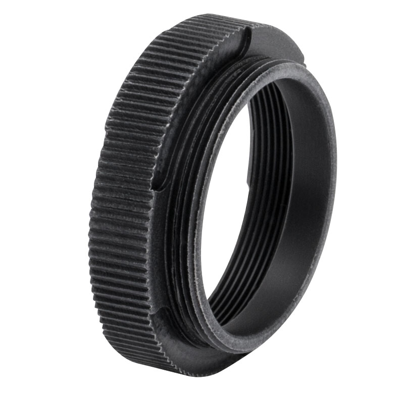
| Item # | SM1A9 | SM1A9TSa | SM1A39 |
|---|---|---|---|
| Image (Click To Enlarge) |
 |
 |
 |
| Thread 1 | External C-Mount (1.00"-32) | ||
| Thread 2 | Internal SM1 (1.035"-40) | External SM1 (1.035"-40) | |
| Material | Anodized Aluminum | Black Delrin®b | Anodized Aluminum |
| Typical Application | Mount a C-Mount Camera to an Externally Threaded SM1 Lens Tube |
Mount a C-Mount Camera to an Externally Threaded SM1 Lens Tube |
Mount a C-Mount Camera to an Internally Threaded SM1 Lens Tube |