 Products Home / Optical Elements / Test Targets, Calibration Targets, and Reticles / Resolution Test Targets
Resolution Test Targets
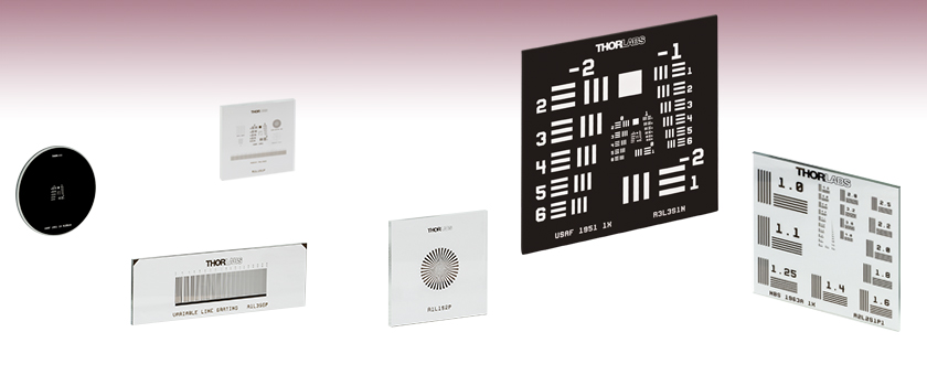
- Test Targets Identify Resolution of an Imaging System
- Positive and Negative Patterns Available
- Combined Resolution and Distortion Targets Available
R1DS1N
Ø1" 1951
USAF Target
R1L3S6P
Variable Line Grating Target
R1L1S1P
Combined Resolution
and Distortion Target
R3L3S1N
Negative 1951 USAF Target
R1L1S2P
Sector Star Target
R2L2S1P1
Positive, High-Frequency
NBS 1963A Target


Please Wait
| Type | Photolithographic | Birefringent |
|---|---|---|
| Design | Chrome-on-Glass | Birefringent Pattern |
| Substrate | Clear Soda Lime Glassb | N-BK7 Glass |
| Chrome Thickness | 0.120 µm | N/A |
| Chrome Optical Density | OD ≥ 3 at 430 nm | N/A |
| Substrate Thickness | 0.06" (1.5 mm) | 0.16" (4.0 mm) |
| Surface Flatness | <50 µm | N/A |
| Line Spacing Tolerancea | ±1 µm | N/A |
| Line Width Tolerancea | ±0.5 µm | N/A |

Features
- Positive and Negative USAF 1951 and NBS 1963A Resolution Test Targets
- Positive NBS 1952 Resolution Test Targets
- Sector Star Targets
- Variable Line Grating Targets
- Combined Resolution and Distortion Target
Resolution test targets are typically used to measure the resolution of an imaging system. They consist of reference line patterns with well-defined thicknesses and spacings and are designed to be placed in the same plane as the object being imaged. By identifying the largest set of non-distinguishable lines, one determines the resolving power of a given system. Thorlabs offers resolution test targets with 1951 USAF, NBS 1952, and NBS 1963A patterns. Targets are also available with sector star (also known as Siemens star) patterns, a variable line grating, or a combination of patterns for resolution and distortion testing. For more information on each pattern, see the Resolution Targets tab.
Many of our resolution test targets are available with positive and negative patterns. The positive targets consist of low-reflectivity, vacuum-sputtered chrome patterns plated on clear substrates and are useful for front-lit and general applications. The negative targets use the same chrome coating to cover the substrates, leaving the patterns clear, and work well in back-lit and highly illuminated applications. Each pattern is manufactured using photolithography, allowing for edge features to be resolved down to approximately 1 µm.
Mounting
These resolution test targets can be mounted in one of four of our microscopy slide holders. Our MAX3SLH Fixed Slide Holder provides two spring clips to mount the optic and can be mounted to any of our 3-axis translation stages. The MAX3SLH is only compatible with test targets greater than or equal to 2" wide and provides a clear aperture of 1", which may cover the chrome pattern on some of the test targets. Thorlabs also offers our XYF1(/M) Test Target Positioning Mount (see photo to the right) capable of translating a 1" to 3" wide rectangular target over a 50 mm x 30 mm area. The mount offers five 8-32 (M4) taps for six post-mountable orientations. The XYF1 uses nylon-tipped setscrews to secure the optic. Please note that the mount's support arms overlap the optic by 4.4 mm on each side. For users of the MLS203 Microscopy stage we offer the MLS203P2 Slide Holder for Inverted Microscopes, which can mount slides 25 mm to 26.5 mm wide and petri dishes 30 mm to 60 mm in diameter.
Photolithographic Target Manufacturing
Our extensive production capabilities enable us to provide solutions for imaging system calibration and measurements. We use contact photolithography with a mask aligner to define the pattern on the glass substrate. Once the pattern is defined, we chemically etch the substrates and clean them in a class 100 cleanroom.
Birefringent Target Manufacturing
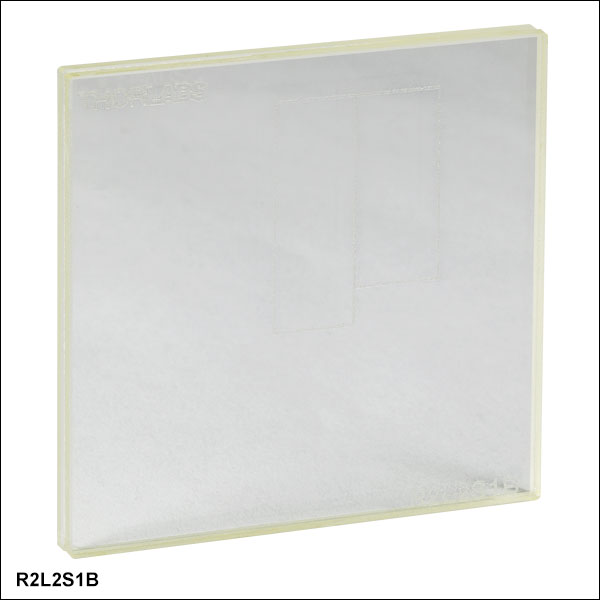
The R2L2S1B Birefringent Resolution Target has a pattern that is invisible unless viewed through a pair of crossed polarizers, making it ideal for calibration of polarization-sensitive systems. It is created by using a photo alignment process to set the fast axis of the liquid crystal polymer layer, which is protected by two N-BK7 glass covers. The device is engineered so that the fast axis of the overall target is aligned parallel to the side of the glass covers, whereas the fast axis for the patterned area is aligned 45° to this edge. The entire target has a retardation of 280 ± 20 nm. Additionally, it can display both positive and negative patterns by changing the orientation of the crossed polarizers. If the crossed polarizers are aligned with the sides of the glass covers, the positive image will be formed. If the crossed polarizers are aligned at 45° to the sides of the glass covers, the negative image will be formed.
Thorlabs also offers a complete line of reticles for superimposing a reference pattern onto an object.
| Targets Selection Guide | |||
|---|---|---|---|
| Resolution Test Targets | Distortion Test Targets | Slant Edge MTF Resolution Test Targets | Calibration Targets |

Click to Enlarge
Line pairs help measure how well a camera can distinguish two objects from one another.
Imaging Resolution
The resolution of an imaging system is often specified in line pairs per millimeter (lp/mm), where a line pair is one light line and one dark line. This value represents the smallest distance between two objects that can be registered by the system; a higher value in lp/mm means the distance between each pair of lines is smaller.
The diagram to the right illustrates the resolution limit of a system. The line pair imaged by the camera on the left cannot be resolved; the two lines are registered by adjacent pixels on the camera sensor, causing them to appear as a single object. In contrast, the line pair on the right has a greater spacing, and thus can be resolved by the system.
The sections below describe the line patterns found on the resolution test targets sold on this page.
1951 USAF Targets
- Conforms to MIL-S-150A Standard
- Spurious Resolution Minimized by Line Sets of Three
- Positive and Negative Targets Available
- 3" x 3" Targets (10 Groups), 3" x 1" Wheel Pattern Targets (6 Groups), 18 mm x 18 mm Combined Targets (6 Groups), and Ø1" Targets (6 Groups)
These resolution targets have a series of horizontal and vertical lines that are used to determine the resolution of an imaging system. A set of six elements (horizontal and vertical line pairs) are in one group, and ten groups compose the resolution chart. The image below shows Elements 2 and 3 of Group -2 on a resolution target.
With line sets of three, these targets offer the advantage of an increased ability to recognize spurious resolution. Spurious resolution occurs when a set of lines is sufficiently blurred such that the overlap appears to form inverted, more distinct lines. This can cause a misreading of the resolution of the optical system, since it will appear that the lines are distinguishable. Spurious resolution also results in the appearance of one less line than exists in the line set. Since the difference between three lines and two is more easily noticed than the difference between five lines and four, for example, it is easier to recognize the occurrence of spurious resolution in targets with sets of only three lines.
The spacing between the lines in each element is equal to the thickness of the line itself. When the target is imaged, the resolution of an imaging system can be determined by viewing the clarity of the horizontal and vertical lines. The largest set of non-distinguishable horizontal and vertical lines determines the resolving power of the imaging system. The chart below lists the number of line pairs per millimeter for a given element within a group based on the equation below. With our resolution targets, the maximum resolution is 228.0 line pairs per millimeter, which equates to roughly 4.4 µm per line pair. The 3" x 3" targets feature ten groups from -2 to +7; the 3" x 1" wheel pattern versions feature 9 targets, each with groups +2 to +7; the 18 mm x 18 mm (0.71" x 0.71") combined targets feature six groups from +2 to +7; and the Ø1" targets feature six groups, from +2 to +7.

Example Line Sets

| Element | Group Number | |||||||||
|---|---|---|---|---|---|---|---|---|---|---|
| -2 | -1 | 0 | 1 | 2 | 3 | 4 | 5 | 6 | 7 | |
| 1 | 0.250 | 0.500 | 1.00 | 2.00 | 4.00 | 8.00 | 16.00 | 32.00 | 64.00 | 128.00 |
| 2 | 0.280 | 0.561 | 1.12 | 2.24 | 4.49 | 8.98 | 17.95 | 36.0 | 71.8 | 144.0 |
| 3 | 0.315 | 0.630 | 1.26 | 2.52 | 5.04 | 10.10 | 20.16 | 40.3 | 80.6 | 161.0 |
| 4 | 0.353 | 0.707 | 1.41 | 2.83 | 5.66 | 11.30 | 22.62 | 45.3 | 90.5 | 181.0 |
| 5 | 0.397 | 0.793 | 1.59 | 3.17 | 6.35 | 12.70 | 25.39 | 50.8 | 102.0 | 203.0 |
| 6 | 0.445 | 0.891 | 1.78 | 3.56 | 7.13 | 14.30 | 28.50 | 57.0 | 114.0 | 228.0 |

Click to Enlarge
Close Up of the R3L3S6P NBS 1952 Target
NBS 1952 Targets
- Allows for One-Pass Scanning
- Spurious Resolution Minimized by Line Sets of Three
- Positive Targets Available
- 1" x 3" and 3" x 3" Sizes
NBS 1952 Targets have sets of three vertical lines and sets of three horizontal lines. Each line and the space between it and the next line can be thought of as a line pair or a cycle. The resolution that each target is able to test is given by the frequency of line pairs in line pairs/mm (lp/mm). A list of every frequency available between our two NBS 1952 targets is given in the table below, along with the corresponding line widths.
These targets offer two main advantages: the minimization of spurious resolution and the feasibility of one-pass scanning. Spurious resolution occurs when a set of lines is sufficiently blurred such that the overlap appears to form inverted, more distinct lines. This can cause a misreading of the resolution of the optical system, since it will appear that the lines are distinguishable. Spurious resolution also results in the appearance of one less line than exists in the line set. Since the difference between three lines and two is more easily noticed than the difference between five lines and four, for example, it is easier to recognize the occurrence of spurious resolution in targets with sets of only three lines.
The advantage of one-pass scanning is made possible by the arrangement of the line sets on these targets. The horizontal and vertical line sets are arranged in an identical fashion, with identical frequencies, such that the target is symmetric across a diagonal line from the upper left to the lower right. If one scans from left to right or from top to bottom on the target, the frequency of the lines will increase until the center is reached and then decrease to the opposite edge. Whether done horizontally or vertically, this single pass across the full pattern covers each frequency available on the target. Thus, movement in only one direction is required to determine the resolution of an optical system.
| Resolution (lp/mm) | Line Width (µm) | Resolution (lp/mm) | Line Width (µm) | Resolution (lp/mm) | Line Width (µm) | Resolution (lp/mm) | Line Width (µm) |
|---|---|---|---|---|---|---|---|
| 0.48 | 1041.7 | 2.24 | 223.2 | 6.8 | 73.5 | 20 | 25 |
| 0.56 | 892.9 | 2.4 | 208.3 | 8 | 62.5 | 24 | 20.8 |
| 0.68 | 735.3 | 2.72 | 183.3 | 9.6 | 52.1 | 28 | 17.9 |
| 0.8 | 625 | 2.8 | 176.8 | 11.2 | 44.6 | 34 | 14.7 |
| 0.96 | 520.8 | 3.2 | 156.3 | 12 | 41.7 | 40 | 12.5 |
| 1.12 | 446.4 | 3.4 | 147.1 | 13.6 | 36.8 | 48 | 10.4 |
| 1.36 | 367.6 | 4 | 125 | 14 | 35.7 | 56 | 8.9 |
| 1.6 | 312.5 | 4.8 | 104.2 | 16 | 31.3 | 68 | 7.4 |
| 1.92 | 260.4 | 5.6 | 89.3 | 17 | 29.4 | 80 | 6.3 |

Click to Enlarge
Microscope Image of R2L2S1N Negative Test Target
NBS 1963A Targets
- Positive, Negative, and Birefringent Targets Available
- High-Frequency Option
- 2" x 2" Size for Dedicated Targets, 1" x 3" Size for Combined Target
NBS 1963A Targets have line sets of five vertical and five horizontal lines. Each line and the space between it and the next line can be thought of as a line pair or a cycle. The resolution that each target is able to test is given by the frequency of the cycles in cycles/mm. On Thorlabs' NBS 1963A targets, each line set is labeled with its frequency. By determining the smallest lines that are distinguishable (highest cycles/mm), you can determine the resolution of an imaging system.
Our standard NBS 1963A targets offer 26 line sets with resolutions scaled from 1.0 cycles/mm to 18.0 cycles/mm. For more rigorous resolution testing, our high-frequency NBS 1963A targets have 48 line sets with frequencies from 1.0 cycles/mm to 228 cycles/mm, and our R1L3S5P combined resolution and distortion test target has 35 line sets with frequencies from 4.5 cycles/mm to 228 cycles/mm. The size of each cycle is simply the reciprocal of the frequency and is given for all available frequencies in the table below. For the individual line width, divide the cycle size in half.
| Cycles/mm | Cycle Size | Cycles/mm | Cycle Size | Cycles/mm | Cycle Size | Cycles/mm | Cycle Size |
|---|---|---|---|---|---|---|---|
| 1.0 | 1.00 mm | 4.0 | 0.250 mm | 16.0 | 0.063 mm | 64.0 | 0.016 mm |
| 1.1 | 0.909 mm | 4.5 | 0.222 mm | 18.0 | 0.056 mm | 72.0 | 0.014 mm |
| 1.25 | 0.800 mm | 5.0 | 0.200 mm | 20.0 | 0.05 mm | 81.0 | 0.012 mm |
| 1.4 | 0.714 mm | 5.6 | 0.179 mm | 23.0 | 0.043 mm | 91.0 | 0.011 mm |
| 1.6 | 0.625 mm | 6.3 | 0.159 mm | 25.0 | 0.040 mm | 102 | 0.010 mm |
| 1.8 | 0.556 mm | 7.1 | 0.141 mm | 29.0 | 0.034 mm | 114 | 0.009 mm |
| 2.0 | 0.500 mm | 8.0 | 0.125 mm | 32.0 | 0.031 mm | 128 | 0.008 mm |
| 2.2 | 0.455 mm | 9.0 | 0.111 mm | 36.0 | 0.028 mm | 144 | 0.007 mm |
| 2.5 | 0.400 mm | 10.0 | 0.100 mm | 40.0 | 0.025 mm | 161 | 0.0062 mm |
| 2.8 | 0.357 mm | 11.0 | 0.091 mm | 45.0 | 0.022 mm | 181 | 0.0055 mm |
| 3.2 | 0.313 mm | 12.5 | 0.080 mm | 51.0 | 0.020 mm | 203 | 0.0049 mm |
| 3.6 | 0.278 mm | 14.0 | 0.071 mm | 57.0 | 0.018 mm | 228 | 0.0044 mm |

Click to Enlarge
Close Up of the R1L1S3P Sector Star Pattern
Sector Star Targets
Sector star targets, also known as Siemens star targets, consist of a number of dark bars that increase in thickness as they radiate out from a shared center. The blank spaces between the bars can themselves be thought of as light bars, and they are designed to be the same thickness as the dark bars at any given radial distance. Theoretically, the bars meet only at the exact middle point of the target. Some sector star targets, including all those sold on this page, have a blank center circle that cuts the bars off before they touch. However, depending on the resolution of the optical system through which the targets are viewed, the bars will appear to touch at some distance from the center. By measuring this distance, the user is able to define the resolution of the optical system.
To calculate the resolution at any given radial distance from the center of the sector star, start by calculating the thickness of a line pair, or one dark bar and one light bar, at that radius. This can be done using the formula for the chord length, given below, where r is the radial distance from the center. The angle Θ is the number of degrees covered by one pair of light and dark bars and is equal to 360° divided by the total number of bars. Once the thickness of the line pair is calculated, the resolution is the reciprocal of the thickness.


Thorlabs offers two dedicated sector star targets (R1L1S2P and R1L1S3P) and three targets that include sector stars along with other patterns (R1L3S5P, R1L1S1P, and R1L1S1N). The table below summarizes the sector star pattern on each target.
| Item # | Pattern Type | Sector Star Pattern Outer Diameter | Center Circle Diameter | Number of Bars | Resolution at Outer Diameter | Resolution at Center Circle |
|---|---|---|---|---|---|---|
| R1L1S2P | Positive | 10 mm | 200 µm | 36 Over 360° | 1.15 lp/mm | 57.5 lp/mm |
| R1L1S3P | 72 Over 360° | 2.29 lp/mm | 115 lp/mm | |||
| R1L3S5P | Positive | 2 mm | 100 µm | 36 Over 360° | 5.75 lp/mm | 115 lp/mm |
| R1L1S1P | Positive | 2 mm | 20 µm | 36 Over 360° | 5.75 lp/mm | 575 lp/mm |
| R1L1S1N | Negative |

Click to Enlarge
Close Up of R1L3S6P Variable Line Grating Pattern
Variable Line Gratings
Line gratings consist of dark, parallel bars with widths that are equal to the distance between them. In any line grating, one dark bar and one blank space compose a line pair. The resolution of an optical system is dependent on its ability to distinguish adjacent line pairs. Thus, the grating resolution is defined by the number of line pairs in a given amount of space and is typically given in line pairs per millimeter (lp/mm). A variable line grating has some number of grating sections, which increase or decrease in resolution as you move from one to the next. By identifying the highest resolution line grating that an optical system is able to resolve, the user determines the resolution of the system.
Thorlabs offers a variable line grating target with a range of resolutions from 1.25 lp/mm to 250 lp/mm. The table below gives the included resolutions along with a conversion of the line pair size.
| lp/mm | Line Pair Size | lp/mm | Line Pair Size | lp/mm | Line Pair Size |
|---|---|---|---|---|---|
| 1.25 | 0.80 mm | 3.85 | 0.26 mm | 16.67 | 0.06 mm |
| 1.67 | 0.60 mm | 4.17 | 0.24 mm | 50 | 0.02 mm |
| 2.08 | 0.48 mm | 5.0 | 0.20 mm | 100 | 0.01 mm |
| 2.5 | 0.40 mm | 6.67 | 0.15 mm | 200 | 0.005 mm |
| 2.86 | 0.35 mm | 10.0 | 0.10 mm | 250 | 0.004 mm |
| 3.33 | 0.30 mm | 12.5 | 0.08 mm | - | - |
| Posted Comments: | |
Ananth Rao
(posted 2020-09-15 06:34:45.553) Hi ,
We have bought this resolution target R1L1S1N, there are two peculiar questions,
1. What is methodology to clean the target? Is there any documentation?
2. What is the surface flatness of the target? YLohia
(posted 2020-09-16 10:32:26.0) Hello, thank you for contacting Thorlabs. Unfortunately, we don't have specific documentation on cleaning the R1L1S1N. That being said, we do have a general optics cleaning guide here: https://www.thorlabs.com/newgrouppage9.cfm?objectgroup_id=9025. I have reached out to you directly to discuss your request. wen cao
(posted 2020-06-24 09:12:46.36) 这个分辨率板是透明的吗?可以背光照射吗? YLohia
(posted 2020-06-24 09:15:24.0) Thank you for contacting Thorlabs. An applications engineer from our team in China (techsupport-cn@thorlabs.com) will reach out to you directly. 程访 许
(posted 2019-11-26 16:41:58.167) 此产品镀的铬膜,对633nm的光,反射率是多少?望回复,我在产品介绍中没看到,最近课题组购买了此产品,我需要这个参数。 nbayconich
(posted 2019-12-03 04:04:53.0) Thank you for contacting Thorlabs. Although we do not specify a guaranteed reflectivity of this chrome coating, the reflectivity will be about 25% at 633nm. I will reach out to you directly. Soocheol Kim
(posted 2019-11-19 21:33:39.29) Dear Sir/Madame,
I checked the retardation of the entire target, which was to be 280±20 nm.
Is this retardation a retardation between the entire target and the patterned area?
I'd like to know the retardation between the entire target and the patterned area. nbayconich
(posted 2019-11-25 10:35:23.0) Thank you for contacting Thorlabs. The R2L2S1B is a half wave plate for 546 nm (or 273nm @546nm). The entire target has the same retardance, the pattern is created by having a 45 deg azimuth difference against the background. Anne De Paepe
(posted 2019-11-06 10:27:10.69) Dear Sir/Madam,
I am looking for a spatial resolution test for my Raman microscope (532nm, 633nm and 785nm lasers). Where I worked before we had a USAF target of Si on Quartz but not sure if this is the best one. What would you recommend?
Thank you YLohia
(posted 2019-11-08 10:51:17.0) Hello, thank you for contacting Thorlabs. Our Chrome on Glass targets are suitable for all wavelengths mentioned by you. Ultimately, the use comes down to personal preference, availability, and possible requirements on transmission/reflectivity. I have reached out to you directly to gain a better sense of your needs. Soojung Kim
(posted 2019-11-05 08:24:52.273) Hello.
How thick is the patterned chrome on R1L1S1P test target? It's very important point to test axial resolution of our equipment.
Sincerely. YLohia
(posted 2019-11-05 10:46:52.0) The thickness of the chrome layer on our targets is 0.120 µm. More information can be found in the specs table in the Overview tab. Fernando Brandi
(posted 2019-08-13 08:52:46.3) Dear Sir/Madame,
I am interested in you R2L2S1B Birefringent NBS 1963A Resolution Target, 2" x 2" for testing a polarizing imaging system.
For our porpoises we need to use both fundamental 1064 nm and second harmonic 532 nm laser light.
In order to evaluate the use of the R2L2S1B Birefringent NBS 1963A Resolution Target for our application I need to know the total optical path length of the target at the two wavelength (1064 nm and 532 nm) and for both ordinary and extraordinary polarization orientation.
Looking forwrd for your reply I thank you for the attention.
Kind regards,
Fernando Brandi, PhD
Consiglio Nazionale delle Ricerche (CNR)
Istituto Nazionale di Ottica (INO)
Sede Secondaria "A. Gozzini" di Pisa
Via Moruzzi 1, 56124-Pisa, Italy
Tel. +39 050 315 2584
Fax. +39 050 315 2247
E-Mail: fernando.brandi@ino.cnr.it
http://research.ino.it/Groups/ilil/it/about_it/ YLohia
(posted 2019-08-28 03:45:30.0) Hello Fernando, thank you for contacting Thorlabs. The design wavelength for half-wave retardance for the R2L2S1B is 546nm. The liquid crystal delta(n) is 0.1555 at 550 nm. Unfortunately, we do not have the data for your exact operating wavelengths. We reached out to you directly to discuss this further. user
(posted 2019-07-01 11:43:13.403) What mechanical mount do you suggest to hold R1L1S1P or R1L1S1N? YLohia
(posted 2019-07-01 12:19:11.0) Hello, thank you for contacting Thorlabs. We recommend the XF50, PC2, FH2, SFH2, CH1A, or FP01 mounts for these targets. Robert Standaert
(posted 2019-05-13 16:45:12.813) High-resolution or vector images of the targets would be very helpful. YLohia
(posted 2019-05-14 10:10:55.0) Hello, thank you for your feedback! We are in the process of discussing the possibility of publishing this information on our website. sureshbil67
(posted 2018-08-11 07:29:46.71) I want to know resolution target patterns specification of Night vision devices YLohia
(posted 2018-09-17 09:59:01.0) Hello, thank you for contacting Thorlabs. I have reached out to you directly to discuss your application in more detail. haolin.zhang
(posted 2018-05-09 20:12:29.3) I am using the R2L2S1B Resolution Target to implement a holographic experiment. Could you please provide me the refractive index of the liquid crystal polymer layer aligned in the target, please? Also, could you please provide the information about the material of this liquid crystal polymer layer? Thanks in advance. YLohia
(posted 2018-05-11 08:39:33.0) Hello, thank you for contacting Thorlabs. Unfortunately, we cannot disclose this information since it is proprietary. ayoub.mghari
(posted 2017-11-29 11:27:24.9) I am interested in ordering this target but I have the following question:
My understanding is that the target is made out of Chrome coating on Soda Lime Glass. This, due to a given illumination system will result in shadows on the rear side, correct?
Is it possible to have this target on a non-transparent glass?
Please send me a Quote by E-mail. nbayconich
(posted 2017-12-27 04:07:26.0) Thank you for contacting Thorlabs. You are correct if using the positive resolution targets then light incident on the front of the target light will reflect off of the chrome patterns. The negative targets have clear patterns with chrome coating the rest of the substrate which makes these intended for back lit applications. We can provide custom targets with non-transparent substrate such as opal. I will reach out to you directly to discuss our custom target capabilities. miguel.pleitez
(posted 2017-05-24 13:59:18.767) would it be possible to get this test targets but on a ZnSe substrate instead of glass? I would be very interested on them. Let me know.
Thanks in advance. nbayconich
(posted 2017-06-13 09:48:26.0) Thank you for contacting Thorlabs. I will contact you directly about our custom capabilities. yoonys
(posted 2016-12-06 01:07:03.37) It'd be helpful to draw what "line pair" is on the website, like Figure 1(b) in the following link.
http://www.edmundoptics.com/resources/application-notes/imaging/resolution/ tcampbell
(posted 2016-12-15 11:47:36.0) Response from Tim at Thorlabs: Thank you for your feedback. We will look into adding a diagram explaining line pairs and camera resolution soon. theodore_morse
(posted 2016-11-16 11:49:07.157) I wish to use a blue laser (266 nm) to get the
resolution. In the masks that you use, will it transmit blue light?
I would prefer it to be a quartz substrate.
Ted Morse
Prof. (Research)
School of Engineering
Brown University
Providence, RI 02912 tfrisch
(posted 2016-11-18 10:32:42.0) Hello Ted, thank you for contacting Thorlabs. I am checking on the transmission and reflection of the chrome and soda lime in UV regions now. I will contact you directly when I have more information. user
(posted 2014-06-02 12:59:19.84) What is the line width of the grids on the R1L1S1P resolution target? jlow
(posted 2014-06-03 10:41:23.0) Response from Jeremy at Thorlabs: The grid line width is 5µm for both the 100µm and 50µm grids, and 1.5µm for the 10µm grid. pnon
(posted 2012-12-24 11:58:00.0) Response from Pauline at Thorlabs: The masks used for our test targets are calibrated to NIST-traceable standards. We use contact photolithography with a mask aligner to define the pattern on the glass substrate. Once the pattern is defined, we chemically etch the substrates to produce the finished targets. Although similar in performance with the mask, we do not provide NIST traceable certificates. I will contact you shortly to provide information in getting targets with NIST certificates. mmarcoux
(posted 2012-12-17 10:05:40.897) Are the R1L3S3P distortion targets N.I.S.T. certified/traceable? tcohen
(posted 2012-06-18 10:51:00.0) Response from Tim at Thorlabs: Information on this question was provided for a previous request @400nm below: “The reflectivity of dark pattern on reticle is less than 12% @400nm. For the white pattern, it is just sodium lime glass, so the reflectivity is estimated to be ~ 3.5% @ 400nm ( assuming refractive index is ~ 1.463).” I have contacted you to find out your wavelength and to see if you require more information. cooljkpark
(posted 2012-06-15 07:09:36.0) Can you tell me the reflection coefficient of glass and chrome in your resolution target? bdada
(posted 2012-06-05 19:09:00.0) Response from Buki at Thorlabs to marctessier:
Thank you for participating in our feedback forum. We are developing some new crossed reticles and we have contacted you for a drawing of the custom reticle you need.
We have an office in France and the information is included on the web page linked below that lists our offices and distributors world wide:
http://www.thorlabs.de/Distributors.cfm marctessier
(posted 2012-06-05 17:31:41.0) Hello,
I'm working in Rillieux la Pape, near Lyon, in France, and I must find a custom 1" crossed reticle. I've a PDF file showing it.
I need only one part.
Are you able to supply such good?
Do you have a french retailer?
Best regards,
Marc bdada
(posted 2012-02-27 17:34:00.0) Response from Buki to dick.verhaart:
For our reticle products, we use chrome with O.D.=>3.0 @430nm. The reflectivity of dark pattern on reticle is less than 12% @400nm. For the white pattern, it is just sodium lime glass, so the reflectivity is estimated to be ~ 3.5% @ 400nm ( assuming refractive index is ~ 1.463).
Please contact TechSupport@thorlabs.com if you have any questions. bdada
(posted 2012-02-24 18:46:00.0) Response from Buki at Thorlabs to dick.verhaart:
Thank you for your feedback. We are looking into this and will contact you shortly with more information and post an update here. dick.verhaart
(posted 2012-02-02 05:48:19.0) Can this product (R3L3S1P/N) be used with 405 nm reflective illumination? I find with similar products from other suppliers that the reflection contrast, at this wavelength, between glass and chrome is very small, contrast reversal may occur. Does Thorlabs specific refelctivity of "black"and "white"at 405 nm? bdada
(posted 2011-08-01 14:14:00.0) Response from Buki at Thorlabs:
We measured the smallest grid pattern (10um) of R1L2S2P using a micrometric system, OLYMPUS MX50, and the tolerance of the pattern is < +/-0.1um. Please contact TechSupport@thorlabs.com with additional questions. ajh
(posted 2011-07-26 03:05:25.0) Can you provide specifications for the accuracy of the graduations on your stage micrometers, R1L2S2P and R1L2S1P? I assume they are very accurate but when calibrating image scale you do want to know how accurate your calibrator is. user
(posted 2011-01-31 10:50:15.0) Response from Buki to Paul. Thank you so much for your feedback. We are expanding our selection of reticles and will make them more compatible with our cage system. We will contact you directly to learn how we can better meet your needs. paul
(posted 2011-01-24 12:02:31.0) I am surprised (given the sophistication of your product line)you do not stock reticles that can be used with the cage plate systems. I currently buy reticles elsewhere and then mount them in cage plates. |

 Zoom
Zoom
- Ø1" (Ø25.4 mm) Targets for Alignment in Ø1" Lens Tubes
- Determine Resolution of an Optical System
- Conforms to MIL-S-150A Standard
- Positive and Negative Patterns Available
- Sets of Three Lines Minimize Spurious Resolution
Thorlabs offers positive and negative Ø1" (Ø25.4 mm) resolution test targets that are made by plating low-reflectivity, vacuum-sputtered chrome on a soda lime glass substrate. These targets have 6 groups (+2 to +7) with 6 elements, offering a maximum resolution of 228.0 line pairs (one light line and one dark line) per millimeter. For more information on the 1951 USAF pattern, please see the Resolution Targets tab above.
Because these targets feature sets of three lines, they reduce the occurrence of spurious resolution and thus help prevent inaccurate resolution measurements. For more information on spurious resolution, please see the Resolution Targets tab.
The R1DS1P positive target consists of a chrome pattern plated on to a clear substrate and is useful for front-lit and general applications. Alternatively, the R1DS1N negative target uses the same chrome coating to cover the substrate, leaving the pattern itself clear, and works well in back-lit and highly illuminated applications.

 Zoom
Zoom
- 3" x 1" (76.2 mm x 25.4 mm) Targets for Measuring Resolution Across Image
- Determine the Resolution of an Optical System
- Conforms to MIL-S-150A Standard
- Positive and Negative Patterns Available
- Compatible with our MLS203 Microscope Stages via MLS203P2 Slide Holder
Thorlabs offers positive and negative 3" x 1" (76.2 mm x 25.4 mm) resolution test targets that are made by plating low-reflectivity, vacuum-sputtered chrome on a soda lime glass substrate. The 3" x 1" wheel pattern targets have 9 USAF 1951 targets, each with 6 groups (+2 to +7), offering a maximum resolution of 228.0 line pairs (one light line and one dark line) per millimeter. For more information on the 1951 USAF pattern, please see the Resolution Targets tab above.
Because these targets feature sets of three lines, they reduce the occurrence of spurious resolution and thus help prevent inaccurate resolution measurements. For more information on spurious resolution, please see the Resolution Targets tab.
The R3L1S4P positive target consists of a chrome pattern plated on to a clear substrate and is useful for front-lit and general applications. Alternatively, the R3L1S4N negative target uses the same chrome coating to cover the substrate, leaving the pattern itself clear, and works well in back-lit and highly illuminated applications.

 Zoom
Zoom- 3" x 3" (76.2 mm x 76.2 mm) Targets Offer Resolution up to 4.4 µm per Line Pair
- Determine Resolution of an Optical System
- Conforms to MIL-S-150A Standard
- Positive and Negative Patterns Available
Thorlabs offers positive and negative 3" x 3" (76.2 mm x 76.2 mm) resolution test targets that are made by plating chrome on a soda lime glass substrate. The 3" x 3" targets have 10 groups (-2 to +7) with 6 elements per group, offering a maximum resolution of 228.0 line pairs (one light line and one dark line) per millimeter. For more information on the 1951 USAF pattern, please see the Resolution Targets tab above.
Because these targets feature sets of three lines, they reduce the occurrence of spurious resolution and thus help prevent inaccurate resolution measurements. For more information on spurious resolution, please see the Resolution Targets tab.
The R3L3S1P positive target consists of a chrome pattern plated on to a clear substrate and is useful for front-lit and general applications. Alternatively, the R3L3S1N negative target uses the same chrome coating to cover the substrate, leaving the pattern itself clear, and works well in back-lit and highly illuminated applications.

 Zoom
Zoom
- 3" x 1" (76.2 mm x 25.4 mm) Target for Measuring Resolution with One-Pass Scanning
- NBS 1952 Target with Centered Crosshair
- Resolutions from 2.4 to 80 lp/mm
- Sets of Three Lines Minimize Spurious Resolution
Thorlabs' 3" x 1" (76.2 mm x 25.4 mm) NBS 1952 Resolution Target offers 48 sets of lines with 24 different frequencies ranging from 2.4 to 80 line pairs (one light line and one dark line) per millimeter (lp/mm), as listed in the table below. In the center of the NBS 1952 target is a crosshair with a length and width of 610 µm and two concentric circles with diameters of 250 µm and 500 µm. Because the line sets on this target are arranged such that every resolution can be viewed by traveling in only one direction (either horizontally or vertically) along the pattern, the resolution of an optical system can be determined with one pass. For more information about the NBS 1952 pattern, please see the Resolution Targets tab above.
Because this target features sets of three lines, it reduces the occurrence of spurious resolution and thus helps prevent inaccurate resolution measurements. For more information on spurious resolution, please see the Resolution Targets tab.
The pattern on this target is made from low-reflectivity, vacuum-sputtered chrome deposited on a 0.06" (1.5 mm) thick soda lime glass substrate to achieve an optical density of ≥3 at 430 nm. The dark pattern and clear substrate are useful for front-lit and general applications.
| NBS 1952 Pattern Resolutions | ||||||||||||||||||||||||
|---|---|---|---|---|---|---|---|---|---|---|---|---|---|---|---|---|---|---|---|---|---|---|---|---|
| Resolution (lp/mm) | 2.4 | 2.8 | 3.4 | 4.0 | 4.8 | 5.6 | 6.8 | 8.0 | 9.6 | 11.2 | 12 | 13.6 | 14 | 16 | 17 | 20 | 24 | 28 | 34 | 40 | 48 | 56 | 68 | 80 |
| Line Width (µm) | 208.3 | 176.8 | 147.1 | 125.0 | 104.2 | 89.3 | 73.5 | 62.5 | 52.1 | 44.6 | 41.7 | 36.8 | 35.7 | 31.3 | 29.4 | 25.0 | 20.8 | 17.9 | 14.7 | 12.5 | 10.4 | 8.9 | 7.4 | 6.3 |

 Zoom
Zoom- 3" x 3" (76.2 mm x 76.2 mm) Target for Measuring Resolution with One-Pass Scanning
- NBS 1952 Target with Centered Crosshair
- Resolutions from 0.48 to 16 lp/mm
- Sets of Three Lines Minimize Spurious Resolution
Thorlabs' 3" x 3" (76.2 mm x 76.2 mm) NBS 1952 Resolution Target offers 48 sets of lines with 24 different frequencies ranging from 0.48 to 16 line pairs (one light line and one dark line) per millimeter (lp/mm), as listed in the table below. In the center of the NBS 1952 target is a crosshair with a length and width of 3100 µm and two concentric circles with diameters of 1250 µm and 2500 µm. Because the line sets on this target are arranged such that every resolution can be viewed by traveling in only one direction (either horizontally or vertically) along the pattern, the resolution of an optical system can be determined with one pass. For more information about the NBS 1952 pattern, please see the Resolution Targets tab above.
Because this target features sets of three lines, it reduces the occurrence of spurious resolution and thus helps prevent inaccurate resolution measurements. For more information on spurious resolution, please see the Resolution Targets tab.
The pattern on this target is made from low-reflectivity, vacuum-sputtered chrome deposited on a 0.06" (1.5 mm) thick soda lime glass substrate to achieve an optical density of ≥3 at 430 nm. The dark pattern and clear substrate are useful for front-lit and general applications.
| NBS 1952 Pattern Resolutions | ||||||||||||||||||||||||
|---|---|---|---|---|---|---|---|---|---|---|---|---|---|---|---|---|---|---|---|---|---|---|---|---|
| Resolution (lp/mm) | 0.48 | 0.56 | 0.68 | 0.8 | 0.96 | 1.12 | 1.36 | 1.6 | 1.92 | 2.24 | 2.4 | 2.72 | 2.8 | 3.2 | 3.4 | 4.0 | 4.8 | 5.6 | 6.8 | 8.0 | 9.6 | 11.2 | 13.6 | 16 |
| Line Width (µm) | 1041.7 | 892.9 | 735.3 | 625 | 520.8 | 446.4 | 367.6 | 312.5 | 260.4 | 223.2 | 208.3 | 183.8 | 176.8 | 156.3 | 147.1 | 125.0 | 104.2 | 89.3 | 73.5 | 62.5 | 52.1 | 44.6 | 36.8 | 31.3 |

 Zoom
Zoom
|
- Frequencies from 1 to 18 cycles/mm (See List to the Right)
- Determine Resolution of an Optical System
- 2" x 2" (50.8 mm x 50.8 mm) Soda Lime Glass Substrate
- Positive and Negative Patterns Available
Thorlabs' 2" x 2" (50.8 mm x 50.8 mm) NBS 1963A resolution test targets offer 26 line sets with frequencies from 1 to 18 cycles/mm, corresponding to cycle sizes from 1.0 mm to 55.6 µm (see the table to the right and the Resolution Targets tab for more information). Each set of lines on the pattern contains five horizontal and five vertical lines and is labeled with the frequency of the lines in cycles/mm, as shown in the images to the right. The resolution of an optical system can be determined by identifying the highest frequency line set that the system is able to resolve.
These resolution targets are offered in positive and negative versions. The R2L2S1P positive target consists of a chrome pattern plated on to a clear substrate and is useful for front-lit and general applications. Alternatively, the R2L2S1N negative target uses the same chrome coating to cover the substrate, leaving the pattern itself clear, and works well in back-lit and highly illuminated applications.

 Zoom
Zoom
Click for Details
Line sets with frequencies of 32 and 29 cycles/mm on the R2L2S1N1 negative target. The enlarged image shows line sets of 7.1 through 228 cycles/mm.

Click for Details
Line sets with frequencies of 32 and 29 cycles/mm on the R2L2S1P1 positive target. The enlarged image shows line sets of 7.1 through 228 cycles/mm.
- Frequencies from 1 to 228 cycles/mm (See List Below)
- Determine Resolution of an Optical System
- 2" x 2" (50.8 mm x 50.8 mm) Soda Lime Glass Substrate
- Positive and Negative Patterns Available
Thorlabs' 2" x 2" (50.8 mm x 50.8 mm) high-frequency NBS 1963A resolution test targets offer 48 line sets with frequencies from 1 to 228 cycles/mm, corresponding to cycle sizes from 1.0 mm to 4.4 µm (see the table below and the Resolution Targets tab for more information). Each set of lines on the pattern contains five horizontal and five vertical lines and is labeled with the frequency of the lines in cycles/mm, as shown in the images to the right. The resolution of an optical system can be determined by identifying the highest frequency line set that the system is able to resolve.
These resolution targets are offered in positive and negative versions. The R2L2S1P1 positive target consists of a chrome pattern plated on to a clear substrate and is useful for front-lit and general applications. Alternatively, the R2L2S1N1 negative target uses the same chrome coating to cover the substrate, leaving the pattern itself clear, and works well in back-lit and highly illuminated applications.
• |

 Zoom
Zoom
Click for Details
This image depicts the pattern placement relative to the inscribed rectangles on the front of the test target.

Click for Details
Image of R2L2S1B as seen through two crossed wire grid polarizers. The enlarged image shows the positive pattern on the left and negative pattern on the right.
- Determine Resolution of a Polarizing Optical System
- Birefringent Target Displays Both Positive and Negative Patterns
- Frequencies from 1 to 18 cycles/mm (See List Below)
- 2" × 2" (50.8 mm × 50.8 mm) N-BK7 Glass Substrate
Thorlabs offers a birefringent 2" x 2" (50.8 mm x 50.8 mm) NBS 1963A resolution test target that is made by sandwiching a birefringent pattern between two N-BK7 glass substrates. The test pattern is only observable if the target is placed between a pair of crossed polarizers (see image to the right).
The target is designed so that it can display both positive and negative patterns by adjusting the orientation of the crossed polarizers relative to the test target. If the cross polarizers are aligned with the sides of the glass covers, the positive image will be formed. If the cross polarizers are aligned at 45° to the sides of the glass covers, the negative image will be formed. Because of its polarization sensitivity, this resolution target is ideal for calibrating and testing the resolution of polarizing microscopes, microscopes with a Nomarski mode, polarization imaging systems, or Mueller Matrix polarimeters.
This target has 26 sets of five horizontal and five vertical lines. Each set of lines is labeled with a number, which refers to the number of cycles per mm. With a maximum frequency of 18 cycles/mm, the smallest cycles are only 0.0556 mm. For more information, please see the Resolution Targets tab above. Since the pattern is only visible through crossed polarizers, the target is inscribed with two rectangles for reference. The image on the far right shows the pattern placement with respect to these inscribed rectangles.
|

 Zoom
Zoom- 1" x 1" (25.4 mm x 25.4 mm) Positive Sector Star Targets
- Determine Resolution of an Optical System
- Low-Reflectivity, Vacuum-Sputtered Chrome on Soda Lime Glass
Thorlabs offers two 1" (25.4 mm) square targets with positive Sector star (also known as Siemens star) patterns. The R1L1S2P target has 36 bars over 360°. The resolution at the center circle of this target is 57.5 lp/mm. Alternatively, the R1L1S3P target has 72 bars over 360°, and the resolution at the center is 115 lp/mm. Both targets also have a Ø200 µm center circle and are useful for determining the resolution of an optical system by noting how close to the center of the pattern an optical system is able to resolve adjacent bars. For more information about sector star patterns, please see the Resolution Targets tab.
| Item # | Pattern Outer Diameter | Center Circle Diameter | Number of Bars | Resolution at Outer Diameter | Resolution at Center Circle |
|---|---|---|---|---|---|
| R1L1S2P | 10 mm | 200 µm | 36 Over 360° | 1.15 lp/mm | 57.5 lp/mm |
| R1L1S3P | 72 Over 360° | 2.30 lp/mm | 115 lp/mm |

 Zoom
Zoom- 3" x 1" (76.2 mm x 25.4 mm) Variable Line Grating Target
- Resolutions from 1.25 lp/mm to 250 lp/mm
- Determine Resolution of an Optical System
- Low-Reflectivity, Vacuum-Sputtered Chrome on Soda Lime Glass
- Compatible with our MLS203 Microscope Stages via MLS203P2 Slide Holder
The R1L3S6P Variable Line Grating Target offers 18 sections of line grating with resolutions ranging from 1.25 line pairs (one light line and one dark line) per millimeter (lp/mm) to 250 lp/mm. The table below lists of each available resolution. The resolution of an optical system can be measured by determining the highest resolution grating with lines that the system is able to resolve.
|
|

 Zoom
Zoom
Click to Enlarge
Close Up of the Smaller Grid on the R3L3S5P Target with Labels Added (See Tables Below)

- Concentric Circles and Crosshair Patterns Arranged in a Grid
- Four Different Concentric Circle Sizes and Five Different Crosshair Sizes
- Measure Resolution, Distortion, and Magnification of an Imaging System
- 3" x 3" (76.2 mm x 76.2 mm) Soda Lime Glass Substrate
Thorlabs' 3" x 3" (76.2 mm x 76.2 mm) Concentric Circle and Crosshair Grid Target offers 289 individual grids, arranged in a larger, 2" x 2" grid of 17 rows and 17 columns. The smaller grids each have four concentric circle patterns and five crosshair patterns of varying sizes. The concentric circle and crosshair patterns on the smaller grids are labeled in the image to the right but not on the target itself. Each concentric circle pattern features seven different radii, while the crosshairs each have a single or a double cross. For details on the dimensions of these patterns, see the tables below.
The pattern on this target is made from low-reflectivity, vacuum-sputtered chrome deposited on a 0.06" (1.5 mm) thick soda lime glass substrate to achieve an optical density of ≥3 at 430 nm. The dark pattern and clear substrate are useful for front-lit and general applications.
| Concentric Circles | |||||||
|---|---|---|---|---|---|---|---|
| Circle Patterna | R1 | R2 | R3 | R4 | R5 | R6 | R7 |
| A1 | 31.3 µm | 62.5 µm | 125 µm | 140.6 µm | 234.4 µm | 242.2 µm | 500 µm |
| A2 | 15.6 µm | 31.3 µm | 62.5 µm | 70.3 µm | 117.2 µm | 121.1 µm | 250 µm |
| A3 | 7.8 µm | 15.6 µm | 31.3 µm | 35.2 µm | 58.6 µm | 60.5 µm | 125 µm |
| A4 | 3.9 µm | 7.8 µm | 15.6 µm | 17.6 µm | 29.3 µm | 30.3 µm | 62.5 µm |
| Crosshairs | |||
|---|---|---|---|
| Crosshair Patterna | Single or Double Line | Length/Width | Line Widthb |
| B1 | Double | 500 µm | 6.25 µm |
| B2 | Double | 500 µm | 12.5 µm |
| B3 | Single | 500 µm | 50 µm |
| B4 | Double | 500 µm | 25 µm |
| B5 | Double | 500 µm | 100 µm |

 Zoom
Zoom
- Measure Image Distortion, Astigmatism, and Other Aberrations
- 18 mm (0.71") Square, 1.5 mm Thick Target
- Determine Resolution of an Optical System
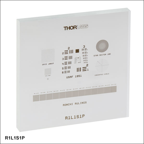
- Includes 1951 USAF Pattern, Sector Star, Concentric Circles, Grids, and Ronchi Rulings
- Positive and Negative Patterns Available
Thorlabs offers positive and negative 18 mm x 18 mm x 1.5 mm combined resolution / distortion test targets that are made by plating vacuum-sputtered, low reflectivity chrome with an optical density of ≥3 at 430 nm on a soda lime glass substrate. They are ideal for calibration of imaging systems and microscope stages.
The test targets include a 1951 USAF pattern (Groups 2 - 7), a sector star, concentric circles, grids (100 µm, 50 µm, and 10 µm), and Ronchi rulings (30 - 150 lp/mm). These targets are useful for testing resolution, field distortion, focus errors, and astigmatism. The USAF 1951 targets are useful for measuring imaging resolution. For more information, please see the Resolution Targets tab above. The grids can be used to measure image distortion, while the concentric circles are ideal for identifying focus errors, astigmatism, and other aberrations existing in an imaging system. The Ronchi rulings are excellent for evaluating resolution, field distortion, and parfocal stability.
These resolution targets are offered in positive and negative versions. The R1L1S1P positive target consists of a chrome pattern plated on to a clear substrate and is useful for front-lit and general applications. Alternatively, the R1L1S1N negative target uses the same chrome coating to cover the substrate, leaving the pattern itself clear, and works well in back-lit and highly illuminated applications.
| Target Feature | Details | Target Feature | Details |
|---|---|---|---|
| 1951 USAF Target | Groups 2 - 7 | Concentric Circles | 10 Circles with Radii from 100 µm to 1000 µm in 100 µm Intervals, Labeled 1 to 10 |
| Grids | 20 x 20 Arrays with 100 µm, 50 µm, and 10 µm Pitch | Ronchi Rulings | 13 Rulings from 30 lp/mma to 150 lp/mm in 10 lp/mm Intervals |
| Sector Star | 36 Bars through 360°, 10 µm Radius Center Circle, and Ten Concentric Circles with Radii from 50 µm to 500 µm in 50 µm Intervals | ||

 Zoom
Zoom|
|
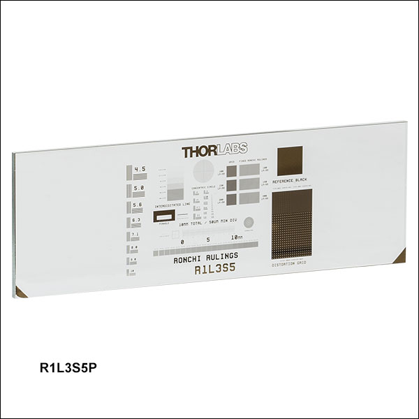
- 3" x 1" (76.2 mm x 25.4 mm) Target
- Includes NBS 1963A Pattern, Sector Star, Concentric Circles, Grids, Ronchi Rulings, and More (See Table Below)
- Determine Resolution of an Optical System
- Measure Image Distortion, Astigmatism, and Other Aberrations
- Compatible with our MLS203 Microscope Stages via MLS203P2 Slide Holder
Thorlabs offers positive 3" x 1" x 0.06" (76.2 mm x 25.4 mm x 1.5 mm) combined resolution / distortion test targets that are made by plating vacuum-sputtered, low reflectivity chrome with an optical density of ≥3 at 430 nm on a soda lime glass substrate. They are ideal for calibration of imaging systems and microscope stages. They are sized to fit in our MLS203P2 stage slide holder for use with our MLS203 microscope stages.
The test targets include an NBS 1963A pattern, a sector (Siemens) star, concentric circles, grids, Ronchi rulings, and more (see table below). These targets are useful for testing resolution, field distortion, focus errors, and astigmatism. The NBS 1963A, sector star, and concentric circle targets are useful for measuring imaging resolution. For more information, please see the Resolution Targets tab above. The grids can be used to measure the distortion introduced by an imaging system. The Ronchi rulings are excellent for evaluating resolution, field distortion, and parfocal stability.
| Target Feature | Details | Target Feature | Details |
|---|---|---|---|
| NBS 1963A | Frequencies from 4.5 cycles/mm to 228 cycles/mm (See List Above) | Concentric Circles | 10 Circles with Radii from 100 µm to 1000 µm in 100 µm Intervals |
| Distortion Grid (Squares) | 3 Grids: 100 lp/mma, 150 lp/mm, 200 lp/mm | Fixed Ronchi Rulings | 3 Rulings:100 lp/mm, 150 lp/mm, and 200 lp/mm |
| Distortion Grid (Dots) | 3 Grids: 400 µm Pitch of Ø80 µm Dots, 200 µm Pitch of Ø 40 µm Dots, 100 µm Pitch of Ø20 µm Dots |
Variable Ronchi Rulings | 20 Rulings (Each 1 mm x 1 mm): 10 lp/mm to 200 lp/mm in 10 lp/mm Intervals |
| Two-Point Resolution Dots | Ø25 µm, Ø20 µm, Ø15 µm, Ø12.5 µm, Ø10 µm, Ø7.5 µm, and Ø5 µm | Pinholes | Ø25 µm, Ø20 µm, Ø15 µm, Ø12.5 µm, Ø10 µm, Ø7.5 µm, and Ø5 µm |
| Interdigitated Lines | 6.25 lp/mm, 12.5 lp/mm, 25 lp/mm, 50 lp/mm, 100 lp/mm, and 200 lp/mm | Micrometers | 3 Rulers: 10 mm Scale with 50 µm Divs, 1 mm Scale with 10 µm Divs, and 1mm x 1 mm XY Scale with 50 µm Divs |
| Sector Star | 36 Bars through 360°, 50 µm Radius Center Circle, and Ten Concentric Circles with Radii from 100 µm to 500 µm in 50 µm Intervals | ||