 Products Home / Imaging Systems & Components / Confocal Microscopy / Upgradeable Single-Channel, Cerna®-Based Confocal Systems
Upgradeable Single-Channel, Cerna®-Based Confocal Systems

- Complete Upright Confocal Imaging Microscopes
- Single-Channel Excitation and Detection
- Large 7.74" Throat Depth Ideal for In Vivo and Intact Specimens
- Upgradeable with More Excitation/Emission Channels and
Widefield Imaging Capabilities
CM201
This Confocal Microscope for GFP Fluorescence Imaging includes a computer, DAQ, and ThorImage®LS Data Acquisition Software.
The optical table, sample holder, and rack are sold separately.


Please Wait

Sam Tesfai
General Manager,
Thorlabs Imaging Systems
Feedback?
Questions?
Need a Quote?


Click for Full Size 2048 x 2048 Image
Dragonfly Eye
| Single-Channel Confocal Microscope Comparisona | ||
|---|---|---|
| Item # | CM100 | CM201 |
| Microscope Type | Reflected Light | GFP Fluorescence |
| Laser | S1FC660 660 nm SM Laser (Red) | S4FC488 488 nm SM Laser (Blue) |
| Scan Head | Galvo-Galvo | |
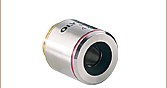
| Objective | RMS20X 20Xb Olympus Objective | N20X-PF 20X Nikon Objective |
| Pinhole | Ø75 µm, Optimized for Included Objective | |
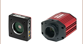
| PMT Detection | One PMT1001/M Multialkali PMT | |

Imaging Capabilities
- Single-Channel Confocal Systems
- Reflected-Light System for Examining Surface Structures
- GFP System for Epi-Fluorescence Imaging
- Complete with All Accessories Needed for Confocal Imaging
- Full Frame 4096 x 4096 Pixel Images (Uni-Directional Scan)
- 884 µm x 884 µm Field of View at 20X Magnification (FN25)
- 2 FPS for 512 x 512 Pixel Bi-Directional Scans
- Galvo-Galvo Scan Head with User-Selectable 1.0 to 10 µs Dwell Times
Microscope Features
- Confocal Scan Path with Galvo-Galvo Scanners
- One Benchtop Excitation Laser
- One Multialkali Photomultiplier Tube (PMT)
- Filter Set for Reflected-Light or GFP Fluorescence Imaging
- One Objective and Matched Ø75 µm Pinhole
- Upright Microscope Based on the Cerna® DIY Microscopy Platform Enables Upgrades to Add Functionality:
- D1N Dovetail on Top of Scan Path Accepts an Epi-Illumination Module or a Cerna Widefield Imaging Module
- 95 mm Dovetail on Rail Accepts Cerna Accessories
- Computer with National Instruments™ (NI) PXIe-6363 X Series DAQ Card
- ThorImage®LS Data Acquisition Software with Lifetime Support
Thorlabs' Upgradeable Single-Channel Confocal Microscopes are complete upright confocal systems. By eliminating signals that originate from outside the focal plane, confocal microscopy provides the ability to acquire high-resolution, optically sectioned images from within a thick sample or to reduce background fluorescence from thin cultures. The CM100 supports confocal reflection imaging, which can be used for viewing the surface structure of biological samples or for inspection applications. The CM201 is optimized for imaging fluorescence produced by green fluorescent protein (GFP). Each system includes a laser, PMT detector, objective, and motorized Z-axis control. See the table to the right for a comparison of key features.
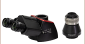
The top panel of each microscope has a female D1N dovetail that allows an epi-illumination module to be added to the system (see below), or Cerna widefield viewing accessories. The microscope body uses the same 95 mm dovetail as our Cerna system, making it easy to integrate trans-illumination modules, sample holders, or custom modules using body attachments built from our large catalog of optomechanics.
The CM100 reflected-light confocal microscope has a PFR14-P02 35 mm x 52 mm x 3 mm silver-coated mirror at the front of the scan path that directs light from the scanners to the objective. In order to use this microscope for widefield as well as confocal imaging, the user can replace this mirror with a beamsplitter or dichroic. The CM201 GFP confocal microscope features a movable silver-coated mirror on a manual slider at the front of the scan path that allows users to select between confocal and widefield imaging modalities without replacing the optic. The body of each confocal microscope also includes a dual-objective changer, allowing the user to easily switch between the 20X objective included for confocal imaging and a user-provided second objective for widefield imaging.
Each microscope includes a PC with a National Instruments (NI) PXIe-6363 X Series DAQ card (see the Specs tab for details) and ThorImageLS data acquisition software. ThorImageLS was developed in conjunction with our laser scanning microscopy systems to provide a seamless, logical, intuitive program for acquiring and analyzing images. This open-source software package enables synchronization of external hardware and events, multi-dimensional data acquisition and display, region-of-interest scanning, and multi-user operation. All images are saved in the standard TIFF image format so that they can be viewed using software packages such as ImageJ/Fiji. See the ThorImageLS tab for additonal information on ThorImageLS features. Upon the purchase of a confocal system, Thorlabs provides lifetime support for the ThorImageLS package.
These systems can be installed by the user and detailed instructions are provided in each manual (included with each system and accessible by clicking on the red documents icon below). An optional installation service is available for these systems. Use our Confocal Microscopy Contact Form for more information.
Specifications for Thorlabs' Upgradeable, Cerna®-Based Confocal Systems available from stock are provided here. If you are interested in a system with different specifications than those listed below, contact our sales team and applications engineers using our Confocal Microscopy Contact Form or at (703) 651-1700.
| Item # | CM100 | CM201 |
|---|---|---|
| System Type | Reflected Light Imaging | GFP Fluorescence Imaging |
| Excitation | ||
| Item # | S1FC660 Single Mode Fiber-Coupled Laser | S4FC488 Single Mode Fiber-Coupled Laser |
| Wavelength | 660 nm | 488 nm |
| Max Output Power | 15 mW (Min) | 16 mW (Min) |
| Power Control | Manual or 0 to 5 V External Signal | |
| Scanning | ||
| Scan Head | Galvo-Galvo | |
| Mirror | PFR14-P02 35 mm x 52 mm x 3 mm Mirror, Protected Silver Coated with λ/4 Surface Flatness (Peak to Valley) | |
| Digitization / Sampling Density | Up to 4096 x 4096 Pixels (Uni-Directional Acquisition) Up to 2048 x 2048 Pixels (Bi-Directional Acquisition) |
|
| Scanning Speed | Up to 2 FPS for 512 x 512 Pixel Bi-Directional Scans with 1 µs Pixel Dwell Time | |
| Pixel Dwell Time | 1.0 - 10.0 µs, Software Selectable | |
| Scan Zoom | 1X to 32X (Continuous) | |
| Diffraction-Limited Field of View | FN25: 796 µm x 796 µm @ 22.2Xa 442 µm x 442 µm @ 40Xb FN23: 733 µm x 733 µm @ 22.2Xa 407 µm x 407 µm FOV @ 40Xb (Field Number is Software Selectable up to FN25) |
FN25: 884 µm x 884 µm @ 20X 442 µm x 442 µm @ 40Xb FN23: 814 µm x 814 µm @ 20X 407 µm x 407 µm FOV @ 40Xb (Field Number is Software Selectable up to FN25) |
| Detection | ||
| Pinhole | Ø75 µm, Optimized for Included 20X Objective | |
| Photomultiplier Tube (PMT) | PMT1001/M Multialkali PMT | |
| Filters | BSW10R 50:50 Beamsplitter WPQ10E-670 Quarter-Wave Plate LPVISE100-A Polarizers (2) |
MD498 Dichroic: Refl. Band = 452 - 490 nm, Trans. Band = 505 - 800 nm MF525-39 Emission Filter: 525 nm / 39 nm |
| Objective | ||
| Item # | RMS20X Olympus Plan Achromat Objective | N20X-PF Nikon Plan Fluorite Objective |
| Magnification | 20Xa | 20X |
| NA | 0.4 | 0.5 |
| Working Distance | 1.2 mm | 2.1 mm |
| Parfocal Length | 45.06 mm | 60 mm |
| Design Tube Lens Focal Length | 180 mma | 200 mm |
| Coverslip Correction | 0.17 mm | |
| Threading | RMS | M25 x 0.75 |
| Fiber Patch Cables | ||
| Laser to Scan Head | P1-630PM-FC-2 2 m PM Patch Cable, 620 - 850 nm, FC/PC Connectors | P1-405B-FC-2 2 m SM Patch Cable, 405 - 532 nm, FC/PC Connectors |
| Pinhole to Detector | FG910UEC MM Fiber, 1 m, Armored Stainless Steel Protective Tubing, AR-Coated End Faces, SMA Connectors | |
| General Microscope Features | ||
| Widefield Viewing | Silver-Coated Mirror can be Removed or Replaced with a Beamsplitter for Widefield Imaging | Silver-Coated Mirror on a Manual Slider to Switch Between Confocal and Widefield Imaging |
| Female D1N Dovetail on Top of Scan Path to Mount Cerna Widefield Viewing Accessories | ||
| Microscope Body | 95 mm Dovetail Rail to Mount Cerna Body Attachments, Transmitted Illumination Modules, and Other Accessories 7.74" Throat Depth |
|
| Nosepiece | CSN200 Dual Objective Changer ZFM2020 Focusing Module with 1" Fine Z Translation M32 x 0.75 Objective Threads (Two Places) M32 x 0.75 to M25 x 0.75 (Qty. 2) and M25 x 0.75 to RMS (Qty. 2) Adapters Included |
|
| Data Acquisition | ||
| Type | National Instruments PXIe-6363 X Series DAQ Card | |
| Analog Outputc | 4 Channels Resolution: 16 Bits Voltage Range: ±10 V Accuracy: 1.89 mV Update Rate: 2.86 MS/s |
|
| Analog Inputc | 1 Channel Resolution: 16 Bits Voltage Range: ±10 V Accuracy: 1.66 mV |
|
| Digital I/Oc | 48 Bidirectional Channels | |
| Clock Rate | 10 MHz (Max) | |
| Frame In/Out Triggering | TTL | |
| Line Trigger Out | TTL | |
| Counter/Timersc | 4 | |
| Computer and Software | ||
| Computer | PC with DAQ | |
| Software | ThorImage®LS with Lifetime Support | |
Thorlabs recognizes that each imaging application has unique requirements.
If you have any feedback, questions, or need a quotation, please contact ImagingSales@thorlabs.com or call (703) 651-1700.

Click to Enlarge
CM100 Components
Grid Slide, Alignment Tool, Computer Keyboard, and Mouse are Not Shown
CM100 Reflected-Light Confocal Microscope
Item # CM100 consists of:
- Single-Channel Reflected-Light Confocal Microscope Body
- Galvo-Galvo Scanner Control Box
- S1FC660 660 nm Single-Channel Fiber-Coupled Laser Source
- KST101 Stepper Motor Controller with USB Cable and KPS101 Power Supply
- PMT1001/M Multialkali PMT
- PH082E Post Holder, TR20/M Post, and CF175 Clamping Fork
- RMS20X 20X Olympus Plan Achromat Objective
- P1-630PM-FC-2 2 m Polarization Maintaining Patch Cable, FC/PC Connectors
- FG910UEC Multimode Fiber in Armored Patch Cable with Stainless Steel Protective Tubing, SMA Connectors
- 120" Long SMA to BNC Cable for Connecting PMT to NI Breakout Box
- Alignment Tool
- R1L3S3P Grid Slide
- NI Breakout Box with NI SHC68-68-EPM and NI SH6868 Cables
- Computer with 24" Monitor, Keyboard, and Mouse
- All Hardware Required for Mounting to an Optical Table
- 12 1/4"-20 and 12 M6 Socket Head Cap Screws
- Six 1/4" (M6) Washers
- 1.5 mm, 2 mm, and 2.5 mm Hex Wrenches
- 2 mm, 5 mm, 3/32" and 3/16" Hex L-Keys

Click to Enlarge
CM201 Components
Fluorescent Bead Slide, Fluorescence Slide, Alignment Tool, Computer Keyboard, and Mouse are Not Shown
CM201 GFP Confocal Microscope
Item # CM201 consists of:
- Single-Channel Fluorescence Confocal Microscope Body
- Galvo-Galvo Scanner Control Box
- S4FC488 488 nm Single-Channel Fiber-Coupled Laser Source
- KST101 Stepper Motor Controller with USB Cable and KPS101 Power Supply
- PMT1001/M Multialkali PMT
- PH082E Post Holder, TR20/M Post, and CF175 Clamping Fork
- N20X-PF 20X Nikon Plan Fluorite Objective
- P1-405B-FC-2 2 m Single Mode Patch Cable, FC/PC Connectors
- FG910UEC Multimode Fiber in Armored Patch Cable with Stainless Steel Protective Tubing, SMA Connectors
- 120" Long SMA to BNC Cable for Connecting PMT to NI Breakout Box
- Alignment Tool
- Fluorescent Bead Slide with 0.1, 0.2, 0.5, 1.0, and 4.0 µm Bead Sizes
- Fluorescence Slide
- NI Breakout Box with NI SHC68-68-EPM and NI SH6868 Cables
- Computer with 24" Monitor, Keyboard, and Mouse
- All Hardware Required for Mounting to an Optical Table
- 12 1/4"-20 and 12 M6 Socket Head Cap Screws
- Six 1/4" (M6) Washers
- 1.5 mm, 2 mm, and 2.5 mm Hex Wrenches
- 2 mm, 5 mm, 3/32" and 3/16" Hex L-Keys
Sam Tesfai
General Manager,
Thorlabs Imaging Systems
Questions?
Feedback?
Need a Quote?

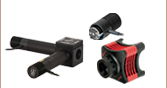
Click to Enlarge
Single-Channel Confocal Microscope Upgraded with Epi-Fluorescence Imaging Functionality. The D1N dovetail on the top of the housing allows Cerna accessories to be added, such as the WFA2001 epi-illumination module, WFA4100 camera tube, and a scientific camera shown here. A silver-coated mirror mounted on a slider in the confocal scan head allows the user to switch between imaging modalities.
Available Upgrades
Each Single-Channel Confocal Microscope is designed so that imaging capabilities can be added to accommodate new experimental needs as your research requirements grow. Some upgrades, such as adding Cerna® widefield imaging accessories, can be easily performed by the user. Others, such as adding additional excitation wavelengths, require replacing part of the hardware, in which case assistance will be provided by our technical staff. Contact us using the link in the green box to the right for additional information.
Four-Channel Upright Confocal Systems that incorporate the Confocal Capability Upgrades listed below are also available.
Widefield Imaging Add-Ons
- Widefield Epi-Illumination with a Six-Filter Removable Turret or Using a Single Filter Cube
- Eyepieces, Trinoculars, and Scientific Cameras for Sample Viewing
- Transmitted Illumination Including Brightfield, Dodt Contrast, and DIC Imaging Modules
- Modules for Mounting Objective Changers, Condensers, and Sample Holders
- Microscope Mover with 2" of Translation in X and Y
Confocal Capability Upgrades
- Up to 4 Excitation Wavelengths
- Up to 4 Confocal Detection Channels with Multialkali or GaAsP PMTs
- Change the Primary Mirror to a Dichroic or Movable Mirror (CM100 Only)
- Change the Galvo-Galvo Scanner to a Galvo-Resonant Scanner
- Add a Motorized Shutter in the Scan Path
- Motorized Pinhole Wheel with 16 Round Sizes from Ø25 μm to Ø2 mm
- Piezo Objective Stage or Z-Axis Piezo Sample Stage for Fast Z-Stacks
- Fast Motorized XY Stage for Large Area Tiling
ThorImage®LS Software
(Click Here for Full Web Presentation)
Features of ThorImage®LS
Comprehensive Imaging Platform for:
- Bergamo® II Multiphoton Microscopes
- DIY Multiphoton Microscope Kits
- Veneto Inverted Microscopes
- Confocal Imaging Systems
- Hyperspectral Imaging System
- Multi-Modality Image Control
Seamless Integration with Experiments
- Simultaneous Multi-Point Photoactivation and Imaging with Spatial Light Modulator
- Fast Z Volume Acquisition with PFM450E or Third-Party Objective Scanners
- Electrophysiology Signaling
- Wavelength Switching with Tiberius® Laser or Coherent Chameleon Lasers
- Pockels Cell ROI Masking
- Power Ramped with Depth to Minimize Damage and Maximize Signal-to-Noise
Advanced Software Functionality
- Multi-Column Customizable Workspace
- Image Acquisition Synced with Hardware Inputs and Timing Events
- Live Image Correction and ROI Analysis
- Independent Galvo-Galvo and Galvo-Resonant Scan Areas and Geometries
- Tiling for High-Resolution Large-Area Imaging
- Independent Primary and Secondary Z-Axis Control for Fast Deep-Tissue Scans
- Automated Image Capture with Scripts
- Compatible with ImageJ Macros
- Multi-User Settings Saved for Shared Workstations
- Individual Colors for Detection Channels Enable Simple Visual Analysis
![]()
The full source code for ThorImage®LS is available for owners of a Bergamo, Cerna, or confocal microscope. Click here to receive your copy.

ThorImageLS is an open-source image acquisition program that controls Thorlabs' microscopes, as well as supplementary external hardware. From prepared-slice multiphoton Z-stacks to simultaneous in vivo photoactivation and imaging, ThorImageLS provides an integrated, modular workspace tailored to the individual needs of the scientist. Its workflow-oriented interface supports single image, Z-stacks, time series, and image streaming acquisition, visualization, and analysis. See the video at the top right for a real-time view of data acquisition and analysis with ThorImageLS.
ThorImageLS is included with a Thorlabs microscope purchase and open source, allowing full customization of software features and performance. ThorImageLS also includes Thorlabs’ customer support and regular software updates to continually meet the imaging demands of the scientific community.
For additional details, see the full web presentation.
New Functionality
Version 4.0 - October 15, 2019
Please contact ImagingTechSupport@thorlabs.com to obtain the latest ThorImageLS version compatible with your microscope. Because ThorImageLS 4.0 adds significant new features over 3.x, 2.x and 1.x versions, it may not be compatible with older microscopes. We continue to support older software versions for customers with older hardware.
- Added Support for Windows® 10 OS
- Added Support for CS895MU and CS505MU Monochrome Cameras (Requires ThorCAM 3.2)
- Allows for Hot Pixel Correction
- Added Support for CSN210 Motorized Dual-Objective Nosepiece
- Allows for Improved Objective Setup and Control
- Added Support for Secondary Three Channel Controller
- Added Support for Second LED of the DC2200 LED Driver
- Added Support for New Version of Thorlabs' Tiberius® Femtosecond Ti:Sapphire Laser
(Up to 1060 nm) - Added Support for Second Channel for GGNI (Allows for Sequential Imaging with 2 Channels)
- Added Support for Controlling Up to 6 Digital Shutters (ThorShutterDig)
- Added Support for Resonant-Galvo-Galvo Scan-Head (Galvo-Resonant or Gavlo-Galvo Scan Modes Only)
- Added Support for Coherent® Discovery with AOM Support (Requires Coherent® Discovery GUI Version 1.8.3 and 3rd Party Virtual Serial Port Software)
- Added Ability to Save Experiment Data in Multi-Page TIFF Format (OME TIFF)
- Added Rapid Image Update for Galvo-Galvo Scanner
- Updates Image Every 16 Scan Lines During Acquisition
- Added Galvo-Galvo External Trigger Sync (Minimum 1 MHz) (GGNI Not Supported)
- Added Improved Galvo-Galvo and Galvo-Resonant Triggering Times
- Added Ability to Read Resonant Frequency Probe
- Added Configurable Trigger Output (Signal Generator) Based on Time or Other Digital Events
- Added Auto Update for Histograms
- Added Dedicated Bleach Shutter Control for Galvo-Galvo and GGNI
- Added Stimulation Epoch Control
- Added Additional Stimulation Features (Pre Idle, Post Idle) and Control Lines (Active, Cycle Output, Epoch)
- Added SLM Multiple Epoch Control (Random Epoch)
- Added Ability to Invert Z Control’s Plus and Minus Buttons (Supports Both Primary and Secondary Z Controllers)
- Added Ability to Display X and Y Positions in Microns or Millimeters
- Added BCM-PA Slider Step Size
- Allows for Setting Slide Step Size When Using Slider Plus and Minus Buttons for Power Adjustment.
- Added Auto Saving of Changed Fine Alignment Values
- Added Ability to Save Image Location and Zoom Level When Switching Image Modalities
- Added ThorSync Changes
- Stack Panel Option
- Virtual Channel
- Renamed “Bleaching” to “Stimulation”
- Added Scale Bar in Image
- Added Help Menu Features
- Allows User to Check for Updates
- Allows User to View Log File for Trouble-Shooting
- Added Shortcuts to Hardware Settings and Application Settings in Hardware Connections Window and Edit Under Settings Menu
- Changed Capture Preview of Image to Show Averaged if Cumulative Mode is Used
- Added Control Digital Switches within Script
- Updated Digital Switch Configuration to be Saved in Experiment Settings and Viewable in Experiment Settings Browser
- Updated Extend Filing Numbering Index Out to 6 Digits
- Fixed - Fast Switching was not Disabled When Hiding Control for Tiberius fs Ti:Sapphire Laser
Laser Scanning Microscopy TutorialLaser scanning microscopy (LSM) is an indispensable imaging tool in the biological sciences. In this tutorial, we will be discussing confocal fluorescence imaging, multiphoton excitation fluorescence imaging, and second and third harmonic generation imaging techniques. We will limit our discussions to point scanning of biological samples with a focus on the technology behind the imaging tools offered by Thorlabs. |
Introduction
The goal of any microscope is to generate high-contrast, high-resolution images. In much the same way that a telescope allows scientists to discern the finest details of the universe, a microscope allows us to observe biological functioning at the nanometer scale. Modern laser scanning microscopes are capable of generating multidimensional data (X, Y, Z, τ, λ), leading to a plethora of high-resolution imaging capabilities that further the understanding of underlying biological processes.
In conventional widefield microscopy (Figure 1, below left), high-quality images can only be obtained when using thin specimens (on the order of one to two cell layers thick). However, many applications require imaging of thick samples, where volume datasets or selection of data from within a specific focal plane is desired. Conventional widefield microscopes are unable to address these needs.
LSM, in particular confocal LSM and multiphoton LSM, allows for the visualization of thin planes from within a thick bulk sample, a technique known as optical sectioning. In confocal LSM, signals generated by the sample outside of the optical focus are physically blocked by an aperture, preventing their detection. Multiphoton LSM, as we will discuss later, does not generate any appreciable signal outside of the focal plane. By combining optical sectioning with incremented changes in focus (Figure 2, below right), laser scanning microscopy techniques can recreate 3D representations of thick specimen.
Figure 1 Widefield Epi-Fluorescence |

Figure 2 Optical Sections (Visualization of Thin Planes within a Bulk Sample)Optical Sectioning in Confocal Microscopy Optical Sectioning in Multiphoton Microscopy Signal generated by the sample is shown in green. Optical sections are formed by discretely measuring the signal generated within a specific focal plane. In confocal LSM, out-of-focus light is rejected through the use of a pinhole aperture, thereby leading to higher resolution. In multiphoton LSM, signal is only generated in the focal volume. Signal collected at each optical section can be reconstructed to create a 3D image. |


Contrast Mechanisms in LSM
Biological samples typically do not have very good contrast, which leads to difficulty in observing the boundaries between adjacent structures. A common method for improving contrast in laser scanning microscopes is through the use of fluorescence.
In fluorescence, a light-emitting molecule is used to distinguish the constituent of interest from the background or neighboring structure. This molecule can already exist within the specimen (endogenous or auto-fluorescence), be applied externally and attached to the constituent (chemically or through antibody binding), or transfected (fluorescent proteins) into the cell.
In order for the molecule to emit light (fluoresce) it must first absorb light (a photon) with the appropriate amount of energy to promote the molecule from the ground state to the excited state, as seen in Figure 3A below. Light is emitted when the molecule returns back down to the ground state. The amount of fluorescence is proportional to the intensity (I) of the incident laser, and so confocal LSM is often referred to as a linear imaging technique. Natural losses within this relaxation process require that the emitted photon have lower energy—that is, a longer wavelength—than the absorbed photon.
Multiphoton excitation (Figure 3B, below) of the molecule occurs when two (or more) photons, whose sum energy satisfies the transition energy, arrive simultaneously. Consequently, the two arriving photons will be of lower energy than the emitted fluorescence photon.
There are also multiphoton contrast mechanisms, such as harmonic generation and sum frequency generation, that use non-absorptive processes. Under conditions in which harmonic generation is allowed, the incident photons are simultaneously annihilated and a new photon of the summed energy is created, as illustrated in Figure 3C below.
Further constituent discrimination can be obtained by observing the physical order of the harmonic generation. In the case of second harmonic generation (SHG), signal is only generated in constituents that are highly ordered and lacking inversion symmetry. Third harmonic generation (THG) is observed at boundary interfaces where there is a refractive index change. Two-photon excitation and SHG are nonlinear processes and the signal generated is dependent on the square of the intensity (I2).
The nonlinear nature of signal generation in multiphoton microscopy means that high photon densities are required to observe SHG and THG. In order to accomplish this while maintaining relatively low average power on the sample, mode-locked femtosecond pulsed lasers, particularly Ti:Sapphire lasers, have become the standard.
Another consideration to be made in nonlinear microscopy is the excitation wavelength for a particular fluorophore. One might think that the ideal excitation wavelength is twice that of the one-photon absorption peak. However, for most fluorophores, the excited state selection rules are different for one- and two-photon absorption.
This leads to two-photon absorption spectra that are quite different from their one-photon counterparts. Two-photon absorption spectra are often significantly broader (can be >100 nm) and do not follow smooth semi-Gaussian curves. The broad two-photon absorption spectrum of many fluorophores facilitates excitation of several fluorescent molecules with a single laser, allowing the observation of several constituents of interest simultaneously.
All of the fluorophores being excited do not have to have the same excitation peak, but should overlap each other and have a common excitation range. Multiple fluorophore excitation is typically accomplished by choosing a compromising wavelength that excites all fluorophores with acceptable levels of efficiency.
Figure 3 Signal Generation in Laser Scanning MicroscopyAbsorptive Process (A, B): The absorption of one or more excitation photons (λEX) promotes the molecule from the ground state (S0) to the excited state (S1). Fluorescence (λEM) is emitted when the molecule returns to the ground state. Non-Absorptive Process (C): The excitation photons (λEX) simultaneously convert into a single photon (λSHG,THG) of the sum energy and half (for SHG) or one-third (for THG) the wavelength.
|


Image Formation
In a point-scanning LSM, the single-plane image is created by a point illumination source imaged to a diffraction-limited spot at the sample, which is then imaged to a point detector. Two-dimensional en face images are created by scanning the diffraction-limited spot across the specimen, point by point, to form a line, then line by line in a raster fashion.
The illuminated volume emits a signal which is imaged to a single-element detector. The most common single-element detector used is a photomultiplier tube (PMT), although in certain cases, avalanche photodiodes (APDs) can be used. CCD cameras are not typically used in point-scanning microscopes, though are the detector of choice in multifocal (i.e. spinning disk confocal) applications.
The signal from the detector is then passed to a computer which constructs a two-dimensional image as an array of intensities for each spot scanned across the sample. Because no true image is formed, LSM is referred to as a digital imaging technique. A clear advantage of single-point scanning and single-point detection is that the displayed image resolution, optical resolution, and scan field can be set to match a particular experimental requirement and are not predefined by the imaging optics of the system.
Figure 4 Confocal Optical Path
|

Confocal LSM
In confocal LSM, point illumination, typically from a single mode, optical-fiber-coupled CW laser, is the critical feature that allows optical sectioning. The light emitted from the core of the single mode optical fiber is collimated and used as the illumination beam for scanning. The scan system is then imaged to the back aperture of the objective lens which focuses the scanned beam to a diffraction-limited spot on the sample. The signal generated by the focused illumination beam is collected back through the objective and passed through the scan system.
After the scan system, the signal is separated from the illumination beam by a dichroic mirror and brought to a focus. The confocal pinhole is located at this focus. In this configuration, signals that are generated above or below the focal plane are blocked from passing through the pinhole, creating the optically sectioned image (Figure 2, above). The detector is placed after the confocal pinhole, as illustrated in Figure 4 to the right. It can be inferred that the size of the pinhole has direct consequences on the imaging capabilities (particularly, contrast, resolution and optical section thickness) of the confocal microscope.
The lateral resolution of a confocal microscope is determined by the ability of the system to create a diffraction-limited spot at the sample. Forming a diffraction-limited spot depends on the quality of the laser beam as well as that of the scan optics and objective lens.
The beam quality is typically ensured by using a single mode optical fiber to deliver the excitation laser light as a Gaussian point source, which is then collimated and focused into a diffraction-limited beam. In an aberration-free imaging system, obtained by using the highest quality optical elements, the size of this focus spot, assuming uniform illumination, is a function of excitation wavelength (λEX) and numerical aperture (NA) of the objective lens, as seen in Equation 1.

Equation 1 Spot Size
In actuality, the beam isn't focused to a true point, but rather to a bullseye-like shape. The spot size is the distance between the zeros of the Airy disk (diameter across the middle of the first ring around the center of the bullseye) and is termed one Airy Unit (AU). This will become important again later when we discuss pinhole sizes.
The lateral resolution of the imaging system is defined as the minimum distance between two points for them to be observed as two distinct entities. In confocal (and multiphoton) LSM, it is common and experimentally convenient to define the lateral resolution according to the full width at half maximum (FWHM) of the individual points that are observed.
Using the FWHM definition, in confocal LSM, the lateral resolution (Rlateral,confocal) is:

Equation 2 Lateral Resolution, Confocal LSM
and the axial resolution (Raxial,confocal) is:

Equation 3 Axial Resolution, Confocal LSM
where n is the refractive index of the immersion medium.
It is interesting to note that in a confocal microscope, the lateral resolution is solely determined by the excitation wavelength. This is in contrast to widefield microscopy, where lateral resolution is determined only by emission wavelength.
To determine the appropriate size of the confocal pinhole, we multiply the excitation spot size by the total magnification of the microscope:

Equation 4 Pinhole Diameter
As an example, the appropriate size pinhole for a 60X objective with NA = 1.0 for λEX = 488 nm (Mscan head = 1.07 for the Thorlabs Confocal Scan Head) would be 38.2 μm and is termed a pinhole of 1 AU diameter. If we used the same objective parameters but changed the magnification to 40X, the appropriate pinhole size would be 25.5 μm and would also be termed a pinhole of 1 AU diameter. Therefore, defining a pinhole diameter in terms of AU is a means of normalizing pinhole diameter, even though one would have to change the pinhole selection for the two different objectives.
Theoretically, the total resolution of a confocal microscope is a function of the excitation illumination spot size and the detection pinhole size. This means that the resolution of the optical system can be improved by reducing the size of the pinhole. Practically speaking, as we restrict the pinhole diameter, we improve resolution and confocality, but we also reduce the amount of signal reaching the detector. A pinhole of 1 AU is a good balance between signal strength, resolution, and confocality.
Figure 5 Multiphoton Optical Path
|

Multiphoton LSM
In multiphoton LSM, a short pulsed free-space laser supplies the collimated illumination beam that passes through the scanning system and is focused by the objective. The very low probability of a multiphoton absorption event occurring, due to the I2 dependence of the signal on incident power, ensures signal is confined to the focal plane of the objective lens. Therefore, very little signal is generated from the regions above and below the focal plane. This effective elimination of out-of-focus signal provides inherent optical sectioning capabilities (Figure 2, above) without the need for a confocal pinhole. As a result of this configuration, the collected signal does not have to go back through the scanning system, allowing the detector to be placed as close to the objective as possible to maximize collection efficiency, as illustrated in Figure 5 to the right. A detector that collects signal before it travels back through the scan system is referred to as a non-descanned detector.
Again using the FWHM defintion, in multiphoton LSM, the lateral resolution (Rlateral,multiphoton) is:

Equation 5 Lateral Resolution, Multiphoton LSM
and the axial resolution (Raxial,multiphoton) is:

Equation 6 Axial Resolution, Multiphoton LSM
These equations assume an objective NA > 0.7, which is true of virtually all multiphoton objectives.
The longer wavelength used for multiphoton excitation would lead one to believe (from Equation 5) that the resolution in multiphoton LSM, compared to confocal LSM, would be reduced roughly by a factor of two. For an ideal point object (i.e. a sub-resolution size fluorescent bead) the I2 signal dependence reduces the effective focal volume, more than offsetting the 2X increase in the focused illumination spot size.
We should note that the lateral and axial resolutions display a dependence on intensity. As laser power is increased, there is a corresponding increase in the probability of signal being generated within the diffraction-limited focal volume. In practice, the lateral resolution in a multiphoton microscope is limited by how tightly the illumination beam can be focused and is well approximated by Equation 5 at moderate intensities. Axial resolution will continue to degrade as excitation power is increased.
Image Display
Although we are not directly rendering an image, it is still important to consider the size of the image field, the number of pixels in which we are displaying our image (capture resolution) on the screen, and the lateral resolution of the imaging system. We use the lateral resolution because we are rendering an en face image. In order to faithfully display the finest features the optical system is capable of resolving, we must appropriately match resolution (capture and lateral) with the scan field. Our capture resolution must, therefore, appropriately sample the optical resolution.
In LSM, we typically rely on Nyquist sampling rules, which state that the pixel size should be the lateral resolution divided by 2.3. This means that if we take our 60X objective from earlier, the lateral resolution is 249 nm (Equation 2) and the pixel size in the displayed image should be 108 nm. Therefore, for a 1024 x 1024 pixel capture resolution, the scan field on the specimen would be ~111 μm x 111 μm. It should be noted that the 40X objective from our previous example would yield the exact same scan field (both objectives have the same NA) in the sample. The only difference between the two images is the angle at which we tilt our scanners to acquire the image.
It may not always be necessary to render images with such high resolution. We can always make the trade-off of image resolution, scan field, and capture resolution to create a balance of signal, sample longevity, and resolution in our images.
Considerations in Live Cell Imaging
One of LSM's greatest attributes is its ability to image living cells and tissues. Unfortunately, some of the by-products of fluorescence can be cytotoxic. As such, there is a delicate balancing act between generating high-quality images and keeping cells alive.
One important consideration is fluorophore saturation. Saturation occurs when increasing the laser power does not provide the expected concurrent increase in the fluorescence signal. This can occur when as few as 10% of the fluorophores are in the excited state.
The reason behind saturation is the amount of time a fluorophore requires to relax back down to the ground state once excited. While the fluorescence pathways are relatively fast (hundreds of ps to a few ns), this represents only one relaxation mechanism. Triplet state conversion and nonradiative decay require significantly longer relaxation times. Furthermore, re-exciting a fluorophore before it has relaxed back down to the ground state can lead to irreversible bleaching of the fluorophore. Cells have their own intrinsic mechanisms for dealing with the cytotoxicity associated with fluorescence, so long as excitation occurs slowly.
One method to reduce photobleaching and the associated cytotoxicity is through fast scanning. While reducing the amount of time the laser spends on a single point in the image will proportionally decrease the amount of detected signal, it also reduces some of the bleaching mechanisms by allowing the fluorophore to completely relax back to the ground state before the laser is scanned back to that point. If the utmost in speed is not a critical issue, one can average several lines or complete frames and build up the signal lost from the shorter integration time.
The longer excitation wavelength and non-descanned detection ability of multiphoton LSM give the ability to image deeper within biological tissues. Longer wavelengths are less susceptible to scattering by the sample because of the inverse fourth power dependence (I-4) of scattering on wavelength. Typical penetration depths for multiphoton LSM are 250 - 500 μm, although imaging as deep as 1 mm has been reported in the literature, compared to ~100 μm for confocal LSM.
Thorlabs recognizes that each imaging application has unique requirements.
If you have any feedback, questions, or need a quotation, please contact ImagingSales@thorlabs.com or call (703) 651-1700.

When viewing an image with a camera, the system magnification is the product of the objective and camera tube magnifications. When viewing an image with trinoculars, the system magnification is the product of the objective and eyepiece magnifications.

| Manufacturer | Tube Lens Focal Length |
|---|---|
| Leica | f = 200 mm |
| Mitutoyo | f = 200 mm |
| Nikon | f = 200 mm |
| Olympus | f = 180 mm |
| Thorlabs | f = 200 mm |
| Zeiss | f = 165 mm |
Magnification and Sample Area Calculations
Magnification
The magnification of a system is the multiplicative product of the magnification of each optical element in the system. Optical elements that produce magnification include objectives, camera tubes, and trinocular eyepieces, as shown in the drawing to the right. It is important to note that the magnification quoted in these products' specifications is usually only valid when all optical elements are made by the same manufacturer. If this is not the case, then the magnification of the system can still be calculated, but an effective objective magnification should be calculated first, as described below.
To adapt the examples shown here to your own microscope, please use our Magnification and FOV Calculator, which is available for download by clicking on the red button above. Note the calculator is an Excel spreadsheet that uses macros. In order to use the calculator, macros must be enabled. To enable macros, click the "Enable Content" button in the yellow message bar upon opening the file.
Example 1: Camera Magnification
When imaging a sample with a camera, the image is magnified by the objective and the camera tube. If using a 20X Nikon objective and a 0.75X Nikon camera tube, then the image at the camera has 20X × 0.75X = 15X magnification.
Example 2: Trinocular Magnification
When imaging a sample through trinoculars, the image is magnified by the objective and the eyepieces in the trinoculars. If using a 20X Nikon objective and Nikon trinoculars with 10X eyepieces, then the image at the eyepieces has 20X × 10X = 200X magnification. Note that the image at the eyepieces does not pass through the camera tube, as shown by the drawing to the right.
Using an Objective with a Microscope from a Different Manufacturer
Magnification is not a fundamental value: it is a derived value, calculated by assuming a specific tube lens focal length. Each microscope manufacturer has adopted a different focal length for their tube lens, as shown by the table to the right. Hence, when combining optical elements from different manufacturers, it is necessary to calculate an effective magnification for the objective, which is then used to calculate the magnification of the system.
The effective magnification of an objective is given by Equation 1:
 |
(Eq. 1) |
Here, the Design Magnification is the magnification printed on the objective, fTube Lens in Microscope is the focal length of the tube lens in the microscope you are using, and fDesign Tube Lens of Objective is the tube lens focal length that the objective manufacturer used to calculate the Design Magnification. These focal lengths are given by the table to the right.
Note that Leica, Mitutoyo, Nikon, and Thorlabs use the same tube lens focal length; if combining elements from any of these manufacturers, no conversion is needed. Once the effective objective magnification is calculated, the magnification of the system can be calculated as before.
Example 3: Trinocular Magnification (Different Manufacturers)
When imaging a sample through trinoculars, the image is magnified by the objective and the eyepieces in the trinoculars. This example will use a 20X Olympus objective and Nikon trinoculars with 10X eyepieces.
Following Equation 1 and the table to the right, we calculate the effective magnification of an Olympus objective in a Nikon microscope:
 |
The effective magnification of the Olympus objective is 22.2X and the trinoculars have 10X eyepieces, so the image at the eyepieces has 22.2X × 10X = 222X magnification.

Sample Area When Imaged on a Camera
When imaging a sample with a camera, the dimensions of the sample area are determined by the dimensions of the camera sensor and the system magnification, as shown by Equation 2.
 |
(Eq. 2) |
The camera sensor dimensions can be obtained from the manufacturer, while the system magnification is the multiplicative product of the objective magnification and the camera tube magnification (see Example 1). If needed, the objective magnification can be adjusted as shown in Example 3.
As the magnification increases, the resolution improves, but the field of view also decreases. The dependence of the field of view on magnification is shown in the schematic to the right.
Example 4: Sample Area
The dimensions of the camera sensor in Thorlabs' 1501M-USB Scientific Camera are 8.98 mm × 6.71 mm. If this camera is used with the Nikon objective and trinoculars from Example 1, which have a system magnification of 15X, then the image area is:
 |
Sample Area Examples
The images of a mouse kidney below were all acquired using the same objective and the same camera. However, the camera tubes used were different. Read from left to right, they demonstrate that decreasing the camera tube magnification enlarges the field of view at the expense of the size of the details in the image.


Click to Enlarge
China Demo Room
Try Our Microscopes In Person or Virtually
Thorlabs' sales engineers and field service staff are based out of eight offices across four continents. We look forward to helping you determine the best imaging system to meet your specific experimental needs. Our customers are attempting to solve biology's most important problems; these endeavors require matching systems that drive industry standards for ease of use, reliability, and raw capability.
Thorlabs' worldwide network allows us to operate demo rooms in a number of locations where you can see our systems in action. We welcome the opportunity to work with you in person or virtually. A demo can be scheduled at any of our showrooms or virtually by contacting ImagingSales@thorlabs.com.
Customer Support Sites
(Click Each Location for More Details)
Newton, New Jersey, USA

Thorlabs HQ
56 Sparta Avenue
Newton, NJ 07860
Customer Support
- Phone: (973) 300-3000
- E-mail: techsupport@thorlabs.com
Ely, United Kingdom

Thorlabs Ltd.
1 Saint Thomas Place, Ely
Ely CB7 4EX
Customer Support
- Phone: +44 (0)1353-654440
- E-mail: techsupport.uk@thorlabs.com
Bergkirchen, Germany

Thorlabs GmbH
Münchner Weg 1
85232 Bergkirchen
Customer Support
- Phone: +49 (0) 8131-5956-0
- E-mail: europe@thorlabs.com
Maisons-Laffitte, France

Thorlabs SAS
109, rue des Cotes
Maisons-Laffitte 78600
Customer Support
- Phone: +33 (0)970 440 844
- E-mail: techsupport.fr@thorlabs.com
São Carlos, SP, Brazil

Thorlabs Vendas de Fotônicos Ltda.
Rua Rosalino Bellini, 175
Jardim Santa Paula
São Carlos, SP, 13564-050
Customer Support
- Phone: +55-16-3413 7062
- E-mail: brasil@thorlabs.com
Demo Rooms and Customer Support Sites
(Click Each Location for More Details)
Sterling, Virginia, USA

Thorlabs Imaging Systems HQ
108 Powers Court
Sterling, VA 20166
Customer Support
- Phone: (703) 651-1700
- E-mail: ImagingTechSupport@thorlabs.com
Demo Rooms
- Bergamo® II Series Multiphoton Microscopes
- Veneto™ Inverted Microscopes
- Single- and Multi-Channel Cerna®-Based Confocal Microscopes
- Confocal Upgrade for Existing Systems
- Cerna Hyperspectral Imaging System
- Multiphoton Mesoscope
- Birefringence Imaging System
- OCT Systems: Vega™, Telesto™, and Ganymede™
Lübeck, Germany

Thorlabs GmbH
Maria-Goeppert-Straße 9
23562 Lübeck
Customer Support
- Phone: +49 (0) 8131-5956-40840
- Email: oct@thorlabs.com
Demo Rooms
- Ganymede™ Series SD-OCT Systems
- Telesto™ Series SD-OCT Systems
- Telesto™ Series PS-OCT Systems
- Atria™ Series SS-OCT Systems
- Vega™ Series SS-OCT Systems
Nerima-ku, Tokyo, Japan

Thorlabs Japan, Inc.
3-6-3 Kitamachi
Nerima-ku, Tokyo 179-0081
Customer Support
- Phone: +81-3-6915-7701
- Email: sales@thorlabs.jp
Demo Rooms
- Four-Channel Cerna®-Based Confocal Systems
- Cerna® Modular Brightfield Microscopes
- OCT Systems: Ganymede™
Shanghai, China

Thorlabs China
Room A101, No. 100, Lane 2891, South Qilianshan Road
Shanghai 200331
Customer Support
- Phone: +86 (0)21-60561122
- Email: techsupport-cn@thorlabs.com
Demo Rooms
- Bergamo® II Series Multiphoton Microscopes
- Single-Channel Cerna®-Based Confocal Microscopes
- Galvo-Galvo or Galvo-Resonant Confocal Upgrade for Existing Systems
- OCT Systems: Telesto™ and Ganymede™
Selected Confocal Microscopy Publications
2020
Caccavano, A. et al. Inhibitory Parvalbumin Basket Cell Activity is Selectively Reduced during Hippocampal Sharp Wave Ripples in a Mouse Model of Familial Alzheimer's Disease. The Journal of Neuroscience
5116–5136 (2020).
2016
Lewin, A. E. et al. Optogenetic and pharmacological evidence that somatostatin-GABA neurons are important regulators of parasympathetic outflow to the stomach. The Journal of Physiology 2661–2679 (2016). doi:10.1113/JP272069
2015
Dechen, K., Richards, C. D., Lye, J. C., Hwang, J. E. C. & Burke, R. Compartmentalized zinc deficiency and toxicities caused by ZnT and Zip gene over expression result in specific phenotypes in Drosophila. The International Journal of Biochemistry & Cell Biology 60, 23–33 (2015).
Jia, Y. et al. Activation of platelet protease-activated receptor-1 induces epithelial-mesenchymal transition and chemotaxis of colon cancer cell line SW620. Oncol. Rep. 33, 2681–2688 (2015).
Lu, W. et al. Inhibiting the mobilization of Ly6Chigh monocytes after acute myocardial infarction enhances the efficiency of mesenchymal stromal cell transplantation and curbs myocardial remodeling. Am J Transl Res 7, 587–597 (2015).
Lu, W. et al. Photoluminescent Mesoporous Silicon Nanoparticles with siCCR2 Improve the Effects of Mesenchymal Stromal Cell Transplantation after Acute Myocardial Infarction. Theranostics 5, 1068–1082 (2015).
Zuo, S., Hughes, M. & Yang, G.-Z. Novel Balloon Surface Scanning Device for Intraoperative Breast Endomicroscopy. Ann Biomed Eng 1–14 (2015). doi:10.1007/s10439-015-1493-2
2014
Brown, C. M., Melcher, J. T. & Stranick, S. J. Scan Linearization for Resonant Optomechanical Systems. in IM1C.3 (OSA, 2014). doi:10.1364/ISA.2014.IM1C.3
Partridge, J. G., Lewin, A. E., Yasko, J. R. & Vicini, S. Contrasting actions of group I metabotropic glutamate receptors in distinct mouse striatal neurones. J Physiol 592, 2721–2733 (2014).
Qin, X., Qiu, C. & Zhao, L. Maslinic acid protects vascular smooth muscle cells from oxidative stress through Akt/Nrf2/HO-1 pathway. Mol Cell Biochem 390, 61–67 (2014).
9.Liu, J. et al. Oleanolic Acid Suppresses Aerobic Glycolysis in Cancer Cells by Switching Pyruvate Kinase Type M Isoforms. PLOS ONE 9, e91606 (2014).
2013
Hao, X. et al. Contrast reversal confocal microscopy. Optics Communications 298–299, 272–275 (2013).
Lalchandani, R. R., Goes, M.-S. van der, Partridge, J. G. & Vicini, S. Dopamine D2 Receptors Regulate Collateral Inhibition between Striatal Medium Spiny Neurons. J. Neurosci. 33, 14075–14086 (2013).
Standard Mechanical Interfaces on DIY Cerna® Components
The table below gives the dovetail, optical component threads, and cage system interfaces that are present on each DIY Cerna component. If a DIY Cerna component does not have one of the standard interfaces in the table, it is not listed here. Please note that mechanical compatibility does not ensure optical compatibility. Information on optical compatibility is available from Thorlabs' web presentations.
| Item # | Microscope Dovetails | Optical Component Threadsa | Cage Systemsb | |||||||||||||
|---|---|---|---|---|---|---|---|---|---|---|---|---|---|---|---|---|
| 95 mm | D1N | D2N | D2NB | D3N | D5N | D1T | D3T | D1Y | D5Y | C-Mountc (1.00"-32) |
SM1d (1.035"-40) |
SM30 (M30.5x0.5) |
SM2e (2.035"-40) |
30 mmd | 60 mme | |
| 2CM1 | Internal & External | Internal | Yes | |||||||||||||
| 2CM2 | Internal & External | Internal | Yes | |||||||||||||
| BSA2000f | Female | |||||||||||||||
| CEA1350 | Male | Female | Yes | |||||||||||||
| CEA1400 | Male | Female | Yes | |||||||||||||
| CEA1500 | Male | Female | Yes | |||||||||||||
| CEA1600 | Male | Female | Yes | |||||||||||||
| CFB1500 | Male | |||||||||||||||
| CSA1000 | Female | |||||||||||||||
| CSA1001 | Female | Internal | Yes | |||||||||||||
| CSA1002 | Female | Internal | Yes | |||||||||||||
| CSA1003 | Female | Yes | ||||||||||||||
| CSA1051 | Female | Male | ||||||||||||||
| CSA1200f,g | Yes | |||||||||||||||
| CSA1400f | Female | Yes | ||||||||||||||
| CSA1500f,h | ||||||||||||||||
| CSA2000f | Female | Internal | Yes | |||||||||||||
| CSA2001 | Female | External | ||||||||||||||
| CSA2100f | Internal | Yes | ||||||||||||||
| CSA3000(/M) | Male | |||||||||||||||
| CSA3010(/M) | Male | Yes | Yes | |||||||||||||
| Item # | 95 mm | D1N | D2N | D2NB | D3N | D5N | D1T | D3T | D1Y | D5Y | C-Mount | SM1 | SM30 | SM2 | 30 mm | 60 mm |
| CSC1001 | Male | |||||||||||||||
| CSC1002 | Male | |||||||||||||||
| CSC1003 | Male | |||||||||||||||
| CSC2001 | Male | |||||||||||||||
| CSD1001 | Male & Female | Female | ||||||||||||||
| CSD1002 | Male & Female | External | ||||||||||||||
| CSE2000 | Male & Female | Yes | ||||||||||||||
| CSE2100 | Male & Female | Female | Internal | Yes | Yes | |||||||||||
| CSE2200 | Male & Female | Female | Internal | Yes | Yes | |||||||||||
| CSN100f,i | Yes | |||||||||||||||
| CSN200i | Male | |||||||||||||||
| CSN210i | Male | |||||||||||||||
| CSN500j | Male | |||||||||||||||
| CSN510k | Male | |||||||||||||||
| CSN1201g,i | ||||||||||||||||
| CSN1202g,j | ||||||||||||||||
| CSS2001 | Female | |||||||||||||||
| LAURE1 | Male | Female | ||||||||||||||
| LAURE2 | Male | Female | ||||||||||||||
| LCPN1 | Male | Internal | Yes | Yes | ||||||||||||
| LCPN2 | Male | Internal | Yes | Yes | ||||||||||||
| LCPN3 | Male | Female | Internal | Yes | ||||||||||||
| Item # | 95 mm | D1N | D2N | D2NB | D3N | D5N | D1T | D3T | D1Y | D5Y | C-Mount | SM1 | SM30 | SM2 | 30 mm | 60 mm |
| OPX2400(/M) | Male & Female | Internal | Yes | |||||||||||||
| SM1A58 | Male | Male | Internal | External | Yes | |||||||||||
| SM2A56 | Male | External | ||||||||||||||
| TC1X | Male | |||||||||||||||
| WFA0150 | Female | |||||||||||||||
| WFA1000 | Yes | |||||||||||||||
| WFA1010 | Internal | Yes | ||||||||||||||
| WFA1020 | Internal | Yes | ||||||||||||||
| WFA1051 | Internal | Yes | ||||||||||||||
| WFA1100 | Yes | |||||||||||||||
| WFA2001 | Male & Female | Internal & External | ||||||||||||||
| WFA2002 | Male & Female | Internal | Yes | |||||||||||||
| WFA4001 | Male | Female | ||||||||||||||
| WFA4002 | Male | Female | ||||||||||||||
| WFA4003 | Male | Female | ||||||||||||||
| WFA4100 | Male | External | Internal | |||||||||||||
| WFA4101 | Male | External | Internal | |||||||||||||
| WFA4102 | Male | External | Internal | |||||||||||||
| WFA4105 | Male | External | ||||||||||||||
| WFA4106 | Male | External | ||||||||||||||
| WFA4107 | Male | External | ||||||||||||||
| WFA4108 | Male | External | ||||||||||||||
| WFA4109 | Male | External | ||||||||||||||
| WFA4110 | Male | External | ||||||||||||||
| WFA4111 | Male | External | ||||||||||||||
| WFA4112 | Male | External | ||||||||||||||
| Item # | 95 mm | D1N | D2N | D2NB | D3N | D5N | D1T | D3T | D1Y | D5Y | C-Mount | SM1 | SM30 | SM2 | 30 mm | 60 mm |
| Female | ||||||||||||||||
| Female | ||||||||||||||||
| Female | ||||||||||||||||
| Female | ||||||||||||||||
| XT95P12(/M) | Female | |||||||||||||||
| ZFM1020 | Female | |||||||||||||||
| ZFM1030 | Female | |||||||||||||||
| ZFM2020 | Female | |||||||||||||||
| ZFM2030 | Female | |||||||||||||||
| Posted Comments: | |
| No Comments Posted |

 Zoom
ZoomTurret Position Sensor Software
Version 4.0 (October 11, 2019)
This software package contains the installation files for the GUI interface, driver, SDK, and support documentation. The software is compatible with Windows® 7 (64 bit) and Windows 10 (64 bit) systems.
 Click to Enlarge
The CSE2000 Epi-Illuminator Module features 4-40 taps to connect to a 60 mm cage system.

Click for Details
The CSE2200 provides a field stop diaphragm and conditioning optics for the main optical path as well as a side port for an additional optical path.
- Included Removable Turret Holds Up to Six Filter Sets without the Need for Filter Cubes
- Monitor Filter Turret Position on a PC Using Included Software Package
- Stackable Design with Female and Male D1N Dovetails on Top and Bottom, Respectively
- Directly Compatible with WFA3110 DIC Analyzer
- CSE2000 Do-It-Yourself Epi-Illuminator Module:
- Build Your Own Optical Path with 60 mm Cage Components
- CSE2200 Ready-to-Use Epi-Illuminator Module:
- Accepts a Collimated Illumination Source via a 60 mm Cage System or D3T Dovetail
- Additional Optical Path Available for 1" Lens Tubes or a 30 mm Cage System
These Epi-Illuminator Modules expand the functionality of our Confocal Microscopes to include fluorescence and brightfield microscopy. With a female D1N dovetail on top and a male D1N dovetail on the bottom, they can be easily added to the microscopes above and accept Cerna widefield viewing modules. Up to six fluorescence filter sets may be installed directly into the turret, allowing for quick and simple switching between imaging different fluorophores without the need for filter cubes; the turret is also available for purchase separately. A mini-USB port on the side of the housing and included GUI software package allow the turret position to be monitored using a PC (not included); see the Software box at the top right for details. Each module also includes a manual shutter to block the illumination beam while not in use and a slot for the WFA3110 DIC analyzer for DIC microscopy.
CSE2200 Ready-To-Use Epi-Illuminator Module
The CSE2200 was designed for use with microscopes that utilize a longer working distance over the epi-illumination path than standard Cerna microscopes, including the confocal microscopes available above. The collimating optics in the primary optical path condition incoming light to provide even widefield illumination at the sample plane. For epi-illuminator modules compatible with our standard Cerna microscopes, see the Cerna Epi-Illumination web presentation.
The primary epi-illumination path features AR-coated optical elements designed for homogeneous illumination over 365 - 700 nm, as well as a field stop diaphragm. A collimated illumination source, such as our Solis® High-Power LED, can be attached using the female D3T dovetail on the back of the module and an SM2A56 adapter, available for purchase below. Light sources with a Ø3 mm or Ø5 mm liquid light guide (LLG) can also be utilized with a LLG collimation adapter. Alternatively, the dovetail can be removed, exposing 4-40 taps that allow a 60 mm cage system to be attached.
An additional optical path can also be utilized by inserting a beamsplitter or dichroic (30 mm x 42 mm, 2.0 ± 0.1 mm in thickness) into the module; please contact Tech Support for compatible dichroics or beamsplitters. The side port features internal SM1 (1.035"-40) threading as well as 4-40 taps for our 30 mm cage system.
CSE2000 Epi-Illuminator Module for Home Builders
The CSE2000 does not include beam conditioning optics, allowing home builders to incorporate custom illumination sources in a Cerna microscope. This standalone module features four 4-40 taps for 60 mm cage systems on the back side. This mechanical interface enables Thorlabs' extensive selection of 60 mm cage components to be used to build custom epi-illumination paths. To utilize the CSE2000 with an existing microscope featuring alternate dovetails, contact Tech Support for a custom solution.
| Specifications |
|---|

 Zoom
Zoomthe WFA2001 Single-Cube Epi-Illuminator Module

Click for Details
Optical Diagram for WFA2001 (See Optical Diagrams Tab for More Details)
- WFA2001: Pre-Installed Optical Path that Accepts an Uncollimated Illumination Source with a Ø3 mm Core Liquid Light Guide or SM1 Threads
- WFA2002: Build Your Own Optical Path using SM1 and 30 mm Cage Components
- Magnetic Door Cover Holds One Olympus-Compatible Filter Cube
- Stackable Design with Female and Male D1N Dovetails on Top and Bottom, Respectively
- MDFM-MF2 Filter Cube is Sold Separately Below
These epi-illuminator modules hold one filter cube in the epi-illumination pathway of a DIY Cerna system. With a female D1N dovetail on top and a male D1N dovetail on the bottom, they are designed to mate with the epi-illumination arm of a Cerna microscope body, as well as with each other. Additional details on dovetails are available in the Microscope Dovetails tab.
The WFA2001 Epi-Illuminator Module's optical input port has internal SM1 (1.035"-40) threads. For this port, we include two adapters: an adapter that accepts a Ø3 mm core liquid light guide and an SM1T10 adapter that accepts an uncollimated light source with an internally SM1-threaded output, such as a mounted LED. For use with a Ø5 mm core liquid light guide, the AD5LLG adapter is available for purchase separately. This module is designed so that evenness of illumination is optimized at a 110 mm working distance between the bottom of the module and the back focal plane of the objective; see the optical diagram to the right. Its pre-installed optical path consists of collimating optics that are AR coated for 350 - 700 nm, as well as field stop and aperture stop diaphragms (Item # SM1D12D) that can be adjusted from Ø0.8 mm to Ø12.0 mm (Ø0.03" to Ø0.47").
In contrast, the WFA2002 Epi-Illuminator Module does not include the pre-installed optical path of the WFA2001. As shown by the photo below, removing the optical path exposes internal SM1 threads and four 4-40 taps for 30 mm cage systems on the back of the module. These mechanical interfaces enable Thorlabs' extensive selection of SM1 and 30 mm cage components to be used to build custom epi-illumination paths.
Each of these modules includes a magnetically secured cover that can be connected to an MDFM-MF2 Filter Cube (sold separately below), as shown by the animation in the upper right. Extra covers, which the user can attach to the filter cubes to speed up filter cube exchange, are sold as Item # WFA2001C.
Please note that these epi-illuminators do not have the slot required for the WFA3110 DIC Analyzer, so a custom mounting solution will be needed. The CSE2100, CSE2000, and CSE2200 Epi-Illuminator Modules sold below are directly compatible with this DIC analyzer.

Click to Enlarge
The WFA2001 Epi-Illuminator Module has a ready-to-use beam path, with field stop and aperture stop diaphragms, for a mounted LED or another uncollimated source with SM1 threads or a Ø3 mm liquid light guide.


The back of the WFA2002 Epi-Illuminator Module has internal SM1 threads and four 4-40 taps for a 30 mm cage system, which can be used to support home-built epi-illumination setups.

 Zoom
Zoom
Click for Details
Remove the Top Plate from the Turret to Install Dichroics or Mirrors

Click to Enlarge
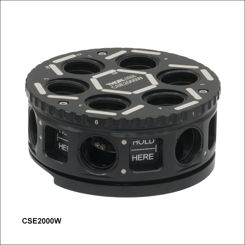
CSE2000W Filter Turret with Top Plate
- Removable Turret Compatible with CSE2000, CSE2100, and CSE2200 Epi-Illuminator Modules
- Easily Install Multiple Filter Sets in a Particular Configuration
- Designed for Use with Thorlabs' and Third-Party Fluorescence Filter Sets
The CSE2000W Turret allows for simple installation of up to six fluorescence filter sets, without the need for filter cubes. This turret directly accepts up to six filter sets without requiring filter cubes: six excitation filters (Ø25.4 mm, <5.1 mm in thickness), six emission filters (Ø25.4 mm, <5.1 mm in thickness), and six rectangular optics (25 mm x 36 mm, 1 ± 0.1 mm in thickness). The emission filters are mounted at a 5° angle to reduce unwanted back reflections. Having multiple filter sets in the same turret, or multiple turrets with particular optic configurations, makes it easy to switch amongst fluorescence filter sets, beamsplitters with crossed polarizers for reflected light imaging, and mirrors. When used with the CSE2000, CSE2100, or CSE2200 epi-illuminator modules (sold above), the turret position can be monitored remotely on a PC with software included with those modules.
The circular optic apertures feature internal SM1 (1.035"-40) threading for simple mounting of Ø1" optical elements; each turret ships with twelve SM1RR retaining rings, one to secure each circular filter. To install the rectangular optics, remove the top plate of the turret by loosening the three M3 screws, then remove the leaf springs to secure each optic. The turret utilizes grip holes on either side of each filter set, both for ease of use and to ensure the optical elements are not touched once installed. Once inserted into an epi-illumination module, simply turn the exposed knurled wheel to switch the filter set in the optical path.

 Zoom
Zoom
Installation of Filters into the MDFM-MF2 Cube
- OEM Filter Cube from Olympus
- Designed for Use with Thorlabs' and Third-Party Fluorescence Filter Sets
This OEM Filter Cube manufactured by Olympus can be used with the WFA2001 The filter cube holds one set of fluorescence filters: an excitation filter (Ø25 mm, up to 5 mm thick), an emission filter (Ø25 mm, up to 3.5 mm thick), and a dichroic mirror (up to 25.2 mm x 36.0 mm x 1.0 mm). Optics can be mounted, aligned, and swapped out easily as illustrated in the video to the right. The filter cube body may be disassembled for optic installation or removal using a Phillips head screwdriver. For detailed assembly instructions, please refer to the assembly manual in the table below.
This filter cube is also available with pre-installed filter sets.
| Item # | Manufacturer Part # |
Microscope Manufacturer |
Compatible Microscopes | Assembly Manual |
|---|---|---|---|---|
| MDFM-MF2 | Olympus U-MF2 | Olympus | AX, BX2, and IX2 series | MDFM-MF2 Manual |
| Thorlabs | Cerna Epi-Fluorescence Microscopes with WFA2001 or WFA2002 Epi-Illuminator Module |
Please contact Tech Support with questions regarding other cube compatibility, mounting, and filter options. Thorlabs does not guarantee compatibility with other industry-standard microscopes not mentioned on this wepage.