 Products Home / Imaging Systems & Components / Microscopes & DIY Components: Cerna Series / Cerna® Series: Modular Microscopy Systems and Components
Cerna® Series: Modular Microscopy Systems and Components

Please Wait
Example Configurations &
Images Taken Using Cerna® Microscope Systems


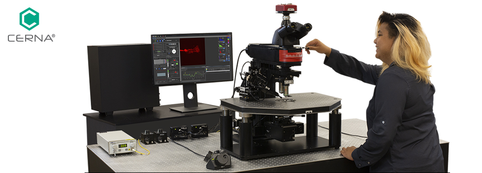
Thorlabs' Cerna® Microscopy Platform
- Supports Conventional Widefield Microscopy Techniques
- Epi-Fluorescence
- Brightfield
- Dodt and DIC
- Modular Design with a Slim Profile and Large Working Volume Underneath and Around
the Objective - Broad Compatibility with Thorlabs' Ø1" Lens Tubes, Ø2" Lens Tubes, 30 mm Cage Systems, and 60 mm Cage Systems
- Add-Ons for Confocal Imaging, Electrophysiology, and Hyperspectral Imaging
Cerna is a modular microscopy platform for applications ranging from routine experiments to advanced optical systems. This platform is designed for users to configure or modify their system to exact experimental requirements, and is especially useful for setups that require large-range adjustment for positioning of the sample or wide-angle access to the objective and other optical components.
Fully Customizable Design
Our modular Cerna components make it simple to adapt this microscopy platform for a wide variety of imaging modalities and experimental applications. We provide several high-performance products, including epi-illuminator modules for one to six filter sets, Dodt gradient contrast and differential interference contrast (DIC) modules for transmitted light imaging, as well as scientific cameras and accessories for widefield and fluorescence imaging. Additionally, this platform's open design is ideal for electrophysiology applications, as it provides access to the focal plane from the front, sides, and even behind. For electrophysiology components, we offer manual and motorized micromanipulators for patch clamping.
The backbone of every Cerna microscope is the microscope body, which is engineered around Thorlabs' 95 mm optical construction rails. Our microscope bodies enable a vertical construction that consumes a minimal amount of space in the horizontal dimension, preserving valuable table space for experimental apparatuses. The microscope body rail offers a linear dovetail mounting surface, excellent vibrational damping, and stable long-term support. Modules such as motorized condensers, sample holders, and our transmitted light imaging modules can be positioned along the rail using a balldriver. The dovetail centers the modules along the optical axis so that the user can minimize painstaking optical alignment procedures.
Easily Expandable with Thorlabs, Industry-Standard, or User-Constructed Add-Ons
For system developers who wish to build microscopes entirely from Thorlabs' catalog of parts (see the For Developers tab for an example), we offer body attachments and extensions that provide connections to our standard mechanical interfaces, including SM1 threads (1.035"-40), SM2 threads (2.035"-40), and taps for 30 mm and 60 mm cage compatibility. Breadboard accessories with either 1/4"-20 or M6 x 1.0 tapped holes attach to the top of the support rail to allow the construction of custom illumination pathways.
| Options at a Glance | |||||
|---|---|---|---|---|---|
| Widefield Imaging | Epi-Illumination | Trans-Illumination | Objective Mounting & Focus Control | Sample Holders & Motion Control |
Body Attachments & Extensions |
 |
 |
 |
 |
 |
|
| Trinoculars with 10X Eyepieces CCD, CMOS, or Scientific-Grade Cameras Optional Double Camera Port |
Modular, User Configurable Epi-Illuminator Modules 25 mm × 36 mm Dichroics & Ø25 mm Filters LEDs & Ø3 mm Liquid Light Guides |
Brightfield, DIC Imaging, and Dodt Contrast Modules DIC Polarizers, Condenser Prisms, & Objective Prisms Air and Oil-Immersion Condensers |
Objective Holders for RMS-, M25 x 0.75-, or M32 x 0.75-Threaded Objectives Motorized Focusing Modules with 1" Travel Piezo Objective Scanner for Fast Z-Stacks |
Rigid Stands Mount Samples & Experimental Apparatuses Motorized XY Scanning Stages for Scanning Up to 250 mm/s XY Platforms for 2" (50 mm) Manual or Motorized Travel |
Integrate Thorlabs' Optomechanical Components into a Cerna Microscope Breadboard Tops, Fixed Arms, and Adapters Provide Compatibility with Lens Tubes and Cage Systems |
Acknowledgements
The red false-colored image on computer screens in the above image and elsewhere is courtesy of Dr. Lei Zhang and Professor Joshua Singer, University of Maryland.
Tailor Your Microscope to Your Experiment
While the microscope below has been designed for electrophysiology, users can easily customize their own microscope to meet diverse experimental needs. Explore the different, exchangeable components of this configuration.

Click to Enlarge
Example Cerna Microscope Configured for Epi-Fluorescence, Differential Interference Contrast (DIC), and Electrophysiology
 |
Micromanipulators Available in manual or motorized configurations, our micromanipulators use piezoelectric elements to enable nanometer-resolution positioning. |
 |
Epi-Illumination To illuminate the field of view from above, Cerna systems can be equipped with liquid light guides or broad-spectrum LEDs. |
 |
Sample Holders Samples may be mounted onto free-standing structures or onto the microscope body itself. Microscope slides, well plates, petri dishes, and supplemental equipment can be mounted, translated, and/or scanned. |
 |
Transmitted Light Illumination Our microscopes are compatible with several kinds of condensers, which provide illumination from underneath the objective. Brightfield, differential interference contrast (DIC) and Dodt gradient contrast are supported. |
 |
Motion Control We manufacture manual and motorized stages that provide one- or two-axis travel for our rigid stands, as well as low-profile XY platforms. We also provide a translator for the entire microscope body. |
 |
Workstations Our vibrationally stabilized optical tables and ScienceDesks are available in several sizes and with a range of shelving options for storage. |
 |
Scientific Cameras Using a double camera port (not shown), up to two cameras can be attached for patch visualization, differential interference contrast (DIC) imaging, or other imaging modalities. |
Example Cerna® System: Developers' Configuration

Click for Details
Through the Use of Fixed Arm Attachments, a Selection of Thorlabs'
Optomechanical Components Are Integrated Into this Cerna® System
- Fixed Arms Integrate Thorlabs' SM1, SM2, 30 mm Cage, and 60 mm Cage Construction Standards with the 95 mm Support Rail
- Breadboard Tops Enable User-Designed Widefield Viewing Schemes
- Ø1.5" Through Hole for Optical Path
- Array of 154 1/4"-20 or M6 x 1.0 Taps
- Two-Position Slider Option to Integrate Multiple Optical Paths
- Custom-Built Illumination Apparatuses Using Thorlabs' Selection of Light Accessories
The configuration shown here contains several microscope body attachments and extensions that are specifically designed for expanding the microscope's functionality using Thorlabs' mechanical construction systems. Intended for system developers, these accessories enable a high degree of system customization.
For instance, the 95 mm support rail has been capped with a breadboard that has a Ø1.5" through hole and an array of 1/4"-20 taps, which here have been used to build a widefield viewing apparatus with our scientific camera and previous-generation plasma light source. Taking advantage of the linear dovetail mounting surface on the support rail, we have attached an SM1-threaded (1.035"-40), 30-mm-cage-compatible fixed arm and an SM2-threaded (2.035"-40), 60-mm-cage-compatible fixed arm in the optical path underneath the objective, allowing us to construct custom transmitted light illumination apparatuses. Please see the full web presentation to explore DIY Cerna options for custom constructions.
| Accessories for DIY Microscopy Construction | |
|---|---|
 |
30 mm and 60 mm Cage Systems Thorlabs' cage systems use four rigid steel rods on which optical components can be mounted along a common optical axis. |
 |
Lens Tubes Lens tubes securely contain custom optical assemblies along the optical axis and can be easily integrated with Cerna components. |
 |
Fiber-Coupled Lasers Thorlabs' extensive line of fiber-coupled laser sources includes both single channel and four channel options. |
 |
LED Light Sources Thorlabs provides a range of mounted LEDs that emit in the UV, visible, NIR, and IR spectral ranges for brightfield illumination, Dodt contrast, and DIC imaging. |
360° Video of Cerna Series Developers' Configuration |
Thorlabs is eager to assist with custom system builds, starting from either the catalog configurations shown here
or parts from our components catalog. Please contact ImagingSales@thorlabs.com to start a conversation.
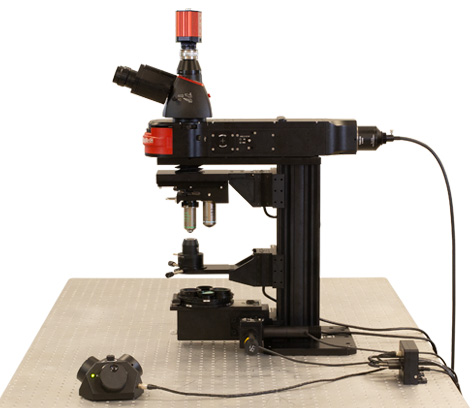
Example Cerna® System: Cerna Microscope for Epi- and Trans-Illumination

Click for Details
This Cerna Microscope has been configured for epi-fluorescence and differential interference contrast (DIC) imaging. This preconfigured microscope is available for purchase here.
- Sliding Nosepiece Accommodates Two Objectives
- Large Throat Depth Supports Free-Standing or Attached Sample Holders
- Capable of Epi-Fluorescence, Brightfield Illumination (Epi or Trans), Differential Interference Contrast (DIC), or Phase Contrast Imaging
- Double Camera Port Enables Two Scientific Cameras to be Individually Dedicated to Widefield Fluorescence and DIC Imaging
This Cerna microscope is configured for both epi-fluorescence and multiple trans-illumination imaging modalities. The preconfigured microscope kit is available for purchase here.
To support epi-fluorescence studies, we have designed this microscope to be compatible with light sources using a liquid light guide. The microscope also utilizes an epi-illuminator module with a removable turret, which enables up to six filter sets to be rotated through the optical path.
For DIC and other trans-illumination modalities, we have outfitted the microscope with several DIC components, including a condenser, polarizers, and prisms. The condenser features an exchangeable tray to mount optics, such as a prism for DIC imaging or condenser mask, inside the condenser. Transmitted illumination is provided by two of Thorlabs' mounted LEDs: a white light LED for brightfield imaging and an 850 nm LED for NIR DIC. Alternate LEDs are available with single wavelength peaks as well as broad spectra. Cerna microscopes are also compatible with Dodt contrast, phase contrast, darkfield, and oblique illumination.
To explore this and our other preconfigured microscope options, see the Preconfigured Microscopes presentation.
| Epi-Fluorescence Accessories | |
|---|---|
 |
Scientific Cameras Thorlabs' sCMOS and scientific CCD cameras are based on high-quantum-efficiency, low-noise imagers, which make them ideal for high-performance imaging techniques. |
 |
Objectives Thorlabs offers several types of objective lenses: infinity-corrected visible imaging objectives, focusing objectives for laser sources, super apochromatic objectives, phase contrast objectives, and reflective objectives. |
 |
Rigid Stand with Slide Holder Thorlabs' Rigid Stands are ideal for mounting our micromanipulators and other electrophysiology accessories such as slide or chamber holders. |
|
LED Light Sources Thorlabs provides a range of mounted LEDs that emit in the UV, visible, NIR, and IR spectral ranges for brightfield illumination, Dodt contrast, and DIC imaging. |
Thorlabs recognizes that each imaging application has unique requirements.
If you have any feedback, questions, or need a quotation, please contact ImagingSales@thorlabs.com or call (703) 651-1700.
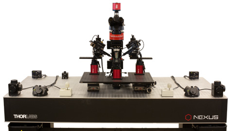
Example Cerna® System: Electrophysiology Microscope for Single-Cell Recording

Click to Enlarge
Since the micromanipulators and recording chamber are mounted on separate rigid stands, this Cerna microscope configuration is best suited for in vitro electrophysiology.
- Liquid-Light-Guide-Based Light Source for Epi-Illumination
- Warm White LED Transmitted Light Source
- Recording Chamber Holder is Motorized for 1" of Travel in X and Y
- Trinoculars and Scientific Camera Provide Visualization of the Sample
This Cerna microscope configuration is designed for single-cell patch clamp recordings. The recording chamber and micromanipulators are held in place by our rigid stands, which offer a quick-release clamp that makes it easy to lock the device in place at the desired position.
Widefield Viewing Accessories
The sample can be viewed directly using the trinoculars or imaged with the scientific camera. For sample excitation, this microscope is equipped with an epi-illuminator module that can hold six filter sets and a broadband light source (not shown) that is delivered through a liquid light guide. Alternative illumination sources include Thorlabs' LEDs or industry-standard broad-spectrum LEDs.
Motion Control for Micromanipulators, Sample Holders, and the Microscope
The motorized XY stage, objective focusing module, and condenser focusing module can be controlled by our 3-axis knobbed controllers, which offer variable speed control and permit axes to be disabled on an individual basis. The motorized micromanipulators have two controllers: a joystick for coarse control of the Y, Z, and approach axes, and a knob box for controlling the piezos. The rigid stands can be moved separately or, alternatively, mounted on an XY platform to be moved as a single group (not shown).
| Electrophysiology Accessories | |||
|---|---|---|---|
|
Scientific Cameras Thorlabs' sCMOS and scientific CCD cameras are based on high-quantum-efficiency, low-noise imagers, which make them ideal for high-performance imaging techniques. |
 |
Motorized Micromanipulators Thorlabs' micromanipulators offer excellent control of pipette manipulation for electrophysiology research. |
 |
Liquid Light Guides Thorlabs' Liquid Light Guides (LLGs) offer high transmission in the UV, visible, NIR, and IR ranges for white light illumination applications. |
|
Objectives Thorlabs offers several types of objective lenses: infinity-corrected visible imaging objectives, focusing objectives for laser sources, super apochromatic objectives, phase contrast objectives, and reflective objectives. |
|
LED Light Sources Thorlabs provides a range of mounted LEDs that emit in the UV, visible, NIR, and IR spectral ranges for brightfield illumination, Dodt contrast, and DIC imaging. |
 |
Rigid Stands Thorlabs' Rigid Stands are ideal for mounting our micromanipulators and other electrophysiology accessories such as slide or chamber holders. |
Thorlabs recognizes that each imaging application has unique requirements.
If you have any feedback, questions, or need a quotation, please contact ImagingSales@thorlabs.com or call (703) 651-1700.

Click to Enlarge
Schematic of Hyperspectral Imaging

Click to Enlarge
A hyperspectral imaging system built using Thorlabs' Cerna® Microscopy Platform, KURIOS-VB1(/M) Tunable Bandpass Filter, and 1501M-GE Monochrome Scientific Camera. Several components shown here were modified from their stock configuration.
Application Idea: Hyperspectral Imaging
In hyperspectral imaging, a stack of spectrally separated, two-dimensional images is acquired. This technique is frequently used in microscopy, biomedical imaging, and machine vision, as it allows quick sample identification and analysis.
Hyperspectral imaging obtains images with significantly better spectral resolution than that provided by standalone color cameras. Color cameras represent the entire spectral range of an image by using three relatively wide spectral channels—red, green, and blue. In contrast, hyperspectral imaging systems incorporate optical elements such as liquid crystal tunable bandpass filters or diffraction gratings, which create spectral channels with significantly narrower bandwidths.
Thorlabs' Cerna® microscopy platform, Kurios® tunable filters, and scientific-grade cameras are easily adapted to hyperspectral imaging. The Cerna platform is a modular microscopy system that integrates with Thorlabs' SM lens tube construction systems and supports transmitted light illumination. Kurios tunable filters have SM-threaded interfaces for connections to the Cerna platform and our cameras. In addition, Kurios filters include software and a benchtop controller with external triggers, which enable fast, automated, synchronized wavelength switching and image capture.
Example Image Stack
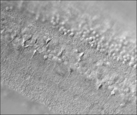
The data in the images and video below demonstrate the hyperspectral imaging technique. Figure 1 depicts two images of a mature capsella bursa-pastoris embryo (also known as shepherd's-purse) taken with a Kurios filter set to center wavelengths of 500 nm and 650 nm. These two images show that an entire field of view is acquired at each spectral channel. Figure 2 is a video containing 31 images of the same sample, taken at center wavelengths from 420 nm to 730 nm in 10 nm steps. (10 nm is not the spectral resolution; the spectral resolution is set by the FWHM bandwidth at each wavelength.) In Figure 3, images from each spectral channel are used to determine the color of each pixel and assemble a color image. Figure 3 also demonstrates that a broadband spectrum is acquired at each pixel, permitting spectroscopic identification of different sample features within the field of view.
Kurios tunable filters offer a number of advantages for hyperspectral imaging. Unlike approaches that rely upon angle-tunable filters or manual filter swapping, Kurios filters use no moving parts, enabling vibrationless wavelength switching on millisecond timescales. Because the filter is not moved or exchanged during the measurement, the data is not subject to "pixel shift" image registration issues. Our filters also include software and a benchtop controller with external triggers, making them easy to integrate with data acquisition and analysis programs.

Click to Enlarge
Figure 3: A color image of the mature capsella bursa-pastoris embryo, assembled using the entire field of view acquired in each spectral channel, as shown in Figure 1. By acquiring across multiple channels, a spectrum for each pixel in the image is obtained.

Click to Enlarge
Figure 1: Two images of a mature capsella bursa-pastoris embryo taken at different center wavelengths. The entire field of view is acquired for each spectral channel.
Figure 2: This video shows the image obtained from the sample as a function of the center wavelength of the KURIOS-WB1 tunable filter. The center wavelength was incremented in 10 nm steps from 420 nm to 730 nm. (10 nm is not the spectral resolution; the spectral resolution is set by the FWHM bandwidth at each wavelength.)
Building a Cerna® Microscope
The Cerna microscopy platform's large working volume and system of dovetails make it straightforward to connect and position the components of the microscope. This flexibility enables simple and stable set up of a preconfigured microscope, and provides easy paths for later upgrades and modification. See below for a couple examples of the assembly of preconfigured and DIY Cerna microscopes.
Preconfigured Microscope Kit Design and Assembly
Walkthrough of Cerna® Microscope Kit 4
This Cerna microscope configuration is equipped with both epi- and trans-illumination modules. All Cerna preconfigured microscope kits enable individual components to be removed or substituted for complete customization.
The D1N and D2N circular dovetails align the sample viewing and epi-illumination apparatus along the optical path. The microscope body's 95 mm linear dovetail is used to secure the objective mounts and condenser mounts, as well as the transmitted light illumination module. The dovetail allows components to slide along the vertical rail prior to lockdown.
DIY Cerna Design and Assembly
Walkthrough of a DIY Microscope Configuration
This DIY microscope uses a CSA3000(/M) Breadboard Top, a CSA2001 Dovetail Adapter, our CSA1001 and CSA1002 Fixed Arms, and other body attachments and extensions. These components provide interfaces to our lens tube and cage construction systems, allowing the rig to incorporate two independent trans-illumination modules, a home-built epi-illumination path, and a custom sample viewing optical path.
DIY Microscope Configuration Assembly
The simplicity of Thorlabs optomechanical interfaces allows a custom DIY microscope to be quickly assembled and reconfigured for custom imaging applications.


Click to Enlarge
China Demo Room
Try Our Microscopes In Person or Virtually
Thorlabs' sales engineers and field service staff are based out of eight offices across four continents. We look forward to helping you determine the best imaging system to meet your specific experimental needs. Our customers are attempting to solve biology's most important problems; these endeavors require matching systems that drive industry standards for ease of use, reliability, and raw capability.
Thorlabs' worldwide network allows us to operate demo rooms in a number of locations where you can see our systems in action. We welcome the opportunity to work with you in person or virtually. A demo can be scheduled at any of our showrooms or virtually by contacting ImagingSales@thorlabs.com.
Customer Support Sites
(Click Each Location for More Details)
Newton, New Jersey, USA

Thorlabs HQ
56 Sparta Avenue
Newton, NJ 07860
Customer Support
- Phone: (973) 300-3000
- E-mail: techsupport@thorlabs.com
Ely, United Kingdom

Thorlabs Ltd.
1 Saint Thomas Place, Ely
Ely CB7 4EX
Customer Support
- Phone: +44 (0)1353-654440
- E-mail: techsupport.uk@thorlabs.com
Bergkirchen, Germany

Thorlabs GmbH
Münchner Weg 1
85232 Bergkirchen
Customer Support
- Phone: +49 (0) 8131-5956-0
- E-mail: europe@thorlabs.com
Maisons-Laffitte, France

Thorlabs SAS
109, rue des Cotes
Maisons-Laffitte 78600
Customer Support
- Phone: +33 (0)970 440 844
- E-mail: techsupport.fr@thorlabs.com
São Carlos, SP, Brazil

Thorlabs Vendas de Fotônicos Ltda.
Rua Rosalino Bellini, 175
Jardim Santa Paula
São Carlos, SP, 13564-050
Customer Support
- Phone: +55-16-3413 7062
- E-mail: brasil@thorlabs.com
Demo Rooms and Customer Support Sites
(Click Each Location for More Details)
Sterling, Virginia, USA

Thorlabs Imaging Systems HQ
108 Powers Court
Sterling, VA 20166
Customer Support
- Phone: (703) 651-1700
- E-mail: ImagingTechSupport@thorlabs.com
Demo Rooms
- Bergamo® II Series Multiphoton Microscopes
- Veneto™ Inverted Microscopes
- Single- and Multi-Channel Cerna®-Based Confocal Microscopes
- Confocal Upgrade for Existing Systems
- Cerna Hyperspectral Imaging System
- Multiphoton Mesoscope
- Birefringence Imaging System
- OCT Systems: Vega™, Telesto™, and Ganymede™
Lübeck, Germany

Thorlabs GmbH
Maria-Goeppert-Straße 9
23562 Lübeck
Customer Support
- Phone: +49 (0) 8131-5956-40840
- Email: oct@thorlabs.com
Demo Rooms
- Ganymede™ Series SD-OCT Systems
- Telesto™ Series SD-OCT Systems
- Telesto™ Series PS-OCT Systems
- Atria™ Series SS-OCT Systems
- Vega™ Series SS-OCT Systems
Nerima-ku, Tokyo, Japan

Thorlabs Japan, Inc.
3-6-3 Kitamachi
Nerima-ku, Tokyo 179-0081
Customer Support
- Phone: +81-3-6915-7701
- Email: sales@thorlabs.jp
Demo Rooms
- Four-Channel Cerna®-Based Confocal Systems
- Cerna® Modular Brightfield Microscopes
- OCT Systems: Ganymede™
Shanghai, China

Thorlabs China
Room A101, No. 100, Lane 2891, South Qilianshan Road
Shanghai 200331
Customer Support
- Phone: +86 (0)21-60561122
- Email: techsupport-cn@thorlabs.com
Demo Rooms
- Bergamo® II Series Multiphoton Microscopes
- Single-Channel Cerna®-Based Confocal Microscopes
- Galvo-Galvo or Galvo-Resonant Confocal Upgrade for Existing Systems
- OCT Systems: Telesto™ and Ganymede™
Click on the different parts of the microscope to explore their functions.

Elements of a Microscope
This overview was developed to provide a general understanding of a Cerna® microscope. Click on the different portions of the microscope graphic to the right or use the links below to learn how a Cerna microscope visualizes a sample.
Terminology
Arm: Holds components in the optical path of the microscope.
Bayonet Mount: A form of mechanical attachment with tabs on the male end that fit into L-shaped slots on the female end.
Bellows: A tube with accordion-shaped rubber sides for a flexible, light-tight extension between the microscope body and the objective.
Breadboard: A flat structure with regularly spaced tapped holes for DIY construction.
Dovetail: A form of mechanical attachment for many microscopy components. A linear dovetail allows flexible positioning along one dimension before being locked down, while a circular dovetail secures the component in one position. See the Microscope Dovetails tab or here for details.
Epi-Illumination: Illumination on the same side of the sample as the viewing apparatus. Epi-fluorescence, reflected light, and confocal microscopy are some examples of imaging modalities that utilize epi-illumination.
Filter Cube: A cube that holds filters and other optical elements at the correct orientations for microscopy. For example, filter cubes are essential for fluorescence microscopy and reflected light microscopy.
Köhler Illumination: A method of illumination that utilizes various optical elements to defocus and flatten the intensity of light across the field of view in the sample plane. A condenser and light collimator are necessary for this technique.
Nosepiece: A type of arm used to hold the microscope objective in the optical path of the microscope.
Optical Path: The path light follows through the microscope.
Rail Height: The height of the support rail of the microscope body.
Throat Depth: The distance from the vertical portion of the optical path to the edge of the support rail of the microscope body. The size of the throat depth, along with the working height, determine the working space available for microscopy.
Trans-Illumination: Illumination on the opposite side of the sample as the viewing apparatus. Brightfield, differential interference contrast (DIC), Dodt gradient contrast, and darkfield microscopy are some examples of imaging modalities that utilize trans-illumination.
Working Height: The height of the support rail of the microscope body plus the height of the base. The size of the working height, along with the throat depth, determine the working space available for microscopy.
 Click to Enlarge
Cerna Microscope Body

Click to Enlarge
Body Details
Microscope Body
The microscope body provides the foundation of any Cerna microscope. The support rail utilizes 95 mm rails machined to a high angular tolerance to ensure an aligned optical path and perpendicularity with the optical table. The support rail height chosen (350 - 600 mm) determines the vertical range available for experiments and microscopy components. The 7.74" throat depth, or distance from the optical path to the support rail, provides a large working space for experiments. Components attach to the body by way of either a linear dovetail on the support rail, or a circular dovetail on the epi-illumination arm (on certain models). Please see the Microscope Dovetails tab or here for further details.
 Click to Enlarge
Illumination with a Cerna microscope can come from above (yellow) or below (orange). Illumination sources (green) attach to either.
Illumination
Using the Cerna microscope body, a sample can be illuminated in two directions: from above (epi-illumination, see yellow components to the right) or from below (trans-illumination, see orange components to the right).
Epi-illumination illuminates on the same side of the sample as the viewing apparatus; therefore, the light from the illumination source (green) and the light from the sample plane share a portion of the optical path. It is used in fluorescence, confocal, and reflected light microscopy. Epi-illumination modules, which direct and condition light along the optical path, are attached to the epi-illumination arm of the microscope body via a circular D1N dovetail (see the Microscope Dovetails tab or here for details). Multiple epi-illumination modules are available, as well as breadboard tops, which have regularly spaced tapped holes for custom designs.
Trans-illumination illuminates from the opposite side of the sample as the viewing apparatus. Example imaging modalities include brightfield, differential interference contrast (DIC), Dodt gradient contrast, oblique, and darkfield microscopy. Trans-illumination modules, which condition light (on certain models) and direct it along the optical path, are attached to the support rail of the microscope body via a linear dovetail (see Microscope Dovetails tab or here). Please note that certain imaging modalities will require additional optics to alter the properties of the beam; these optics may be easily incorporated in the optical path via lens tubes and cage systems. In addition, Thorlabs offers condensers, which reshape input collimated light to help create optimal Köhler illumination. These attach to a mounting arm, which holds the condenser at the throat depth, or the distance from the optical path to the support rail. The arm attaches to a focusing module, used for aligning the condenser with respect to the sample and trans-illumination module.
 |
 |
 |
 |
 |
 |
 |
 |
| Epi-Illumination Modules | Breadboards & Body Attachments |
Brightfield | DIC | Dodt | Condensers | Condenser Mounting | Light Sources |
 Click to Enlarge
Light from the sample plane is collected through an objective (blue) and viewed using trinocs or other optical ports (pink).
Sample Viewing/Recording
Once illuminated, examining a sample with a microscope requires both focusing on the sample plane (see blue components to the right) and visualizing the resulting image (see pink components).
A microscope objective collects and magnifies light from the sample plane for imaging. On the Cerna microscope, the objective is threaded onto a nosepiece, which holds the objective at the throat depth, or the distance from the optical path to the support rail of the microscope body. This nosepiece is secured to a motorized focusing module, used for focusing the objective as well as for moving it out of the way for sample handling. To ensure a light-tight path from the objective, the microscope body comes with a bellows (not pictured).
Various modules are available for sample viewing and data collection. Trinoculars have three points of vision to view the sample directly as well as with a camera. Double camera ports redirect or split the optical path among two viewing channels. Camera tubes increase or decrease the image magnification. For data collection, Thorlabs offers both cameras and photomultiplier tubes (PMTs), the latter being necessary to detect fluorescence signals for confocal microscopy. Breadboard tops provide functionality for custom-designed data collection setups. Modules are attached to the microscope body via a circular dovetail (see the Microscope Dovetails tab or here for details).


 Click to Enlarge
The rigid stand (purple) pictured is one of various sample mounting options available.
Sample/Experiment Mounting
Various sample and equipment mounting options are available to take advantage of the large working space of this microscope system. Large samples and ancillary equipment can be mounted via mounting platforms, which fit around the microscope body and utilize a breadboard design with regularly spaced tapped through holes. Small samples can be mounted on rigid stands (for example, see the purple component to the right), which have holders for different methods of sample preparation and data collection, such as slides, well plates, and petri dishes. For more traditional sample mounting, slides can also be mounted directly onto the microscope body via a manual XY stage. The rigid stands can translate by way of motorized stages (sold separately), while the mounting platforms contain built-in mechanics for motorized or manual translation. Rigid stands can also be mounted on top of the mounting platforms for independent and synchronized movement of multiple instruments, if you are interested in performing experiments simultaneously during microscopy.
 |
 |
 |
 |
 |
| Translating Platforms | Rigid Stands | Translation Stages for Rigid Stands | Motorized XY Stages | Manual XY Stage |
For sample viewing, Thorlabs offers trinoculars, double camera ports, and camera tubes. Light from the sample plane can be collected via cameras, photomultiplier tubes (PMTs), or custom setups using breadboard tops. Click here for additional information about viewing samples with a Cerna microscope.
| Product Families & Web Presentations | |||
 |
|
 |
 |
| Sample Viewing | Breadboards & Body Attachments |
Cameras | PMTs |
Microscope objectives are held in the optical path of the microscope via a nosepiece. Click here for additional information about viewing a sample with a Cerna microscope.
| Product Families & Web Presentations | ||||
 |
 |
 |
 |
 |
| Objectives | Objective Thread Adapters | Parfocal Length Extender | Piezo Objective Scanner | Objective Mounting |
Large and small experiment mounting options are available to take advantage of the large working space of this microscope. Click here for additional information about mounting a sample for microscopy.
| Product Families & Web Presentations | ||||
|
|
|
|
 |
| Translating Platforms | Rigid Stands | Translation Stages for Rigid Stands | Motorized XY Stages | Manual XY Stage |
Thorlabs offers various light sources for epi- and trans-illumination. Please see the full web presentation of each to determine its functionality within the Cerna microscopy platform.
| Product Families & Web Presentations | ||||
 |
 |
 |
 |
|
| Trans-Illumination Kits | Solis™ High-Power LEDs | Mounted LEDs | X-Cite® Lamps | Other Light Sources |
Epi-illumination illuminates the sample on the same side as the viewing apparatus. Example imaging modalities include fluorescence, confocal, and reflected light microscopy. Click here for additional information on epi-illumination with Cerna.
| Product Families & Web Presentations | ||
|
|
|
| Epi-Illumination | Body Attachments | Light Sources |
Trans-illumination illuminates from the opposite side of the sample as the viewing apparatus. Example imaging modalities include brightfield, differential interference contrast (DIC), Dodt gradient contrast, oblique, and darkfield microscopy. Click here for additional information on trans-illumination with Cerna.
| Product Families & Web Presentations | ||||||
|
|
|
|
 |
|
|
| Brightfield | DIC | Dodt | Condensers | Condenser Mounting | Illumination Kits | Other Light Sources |
The microscope body provides the foundation of any Cerna microscope. The 7.74" throat depth provides a large working space for experiments. Click here for additional information about the Cerna microscope body.
| Product Families & Web Presentations | |
 |
 |
| Microscope Bodies | Microscope Translator |