 Products Home / Imaging Systems & Components / Microscopy Components / Stages for Microscopy / XYZ Microscope Stages
XYZ Microscope Stages

- Ideal for use in 3D Imaging Applications
- X and Y Position Accuracy: <3.0 µm
- Z-Axis Resolution: 25 nm
- Compatible with Cerna®, Nikon, Olympus, and Zeiss Microscopes
Motorized XYZ Scanning
MZS500-E Z-Axis Stage and MLS203-1 XY
Stage Shown with the MZS500P2 Slide Holder
MZS500-E Z-Axis Stage Mounted
to an MLS203-1 XY Microscopy
Stage, Shown Attached to a Nikon
Eclipse Ti-U Microscope.


Please Wait

A typical XYZ stage setup is comprised of an MLS203 stage and controller with the MZS500-E Z-Axis Piezo Stage and Controller, MZF001 Z-Axis Joystick, and inverted Olympus microscope.
Features
- XY DC Linear Servo Stage with Position Accuracy of <3.0 µm
- Mounting Bracket Available for Thorlabs' Cerna®, Nikon, Olympus, or Zeiss Microscopes
- Z-Axis Piezo Stage with 500 µm of Vertical Travel and 25 nm Resolution
- Mount to Compatible XY Scanning Stage for Complete XYZ Microscope Stage
- XYZ Microscope Stage Specimen Holders and Accessories Available
The MLS203/MZS500-E motorized XYZ microscope stage system presents a 3D positioning solution for applications such as Z-axis slicing or 3D image collection, including laser scanning microscopy. It provides active feedback to compensate for thermal changes and other factors that might lead to stage drift. The closed-loop, active feedback ensures correct positioning with submicron repeatability and Z-axis resolution of 25 nm, making the XYZ stage system ideal for applications that require highly accurate focus control. To build a complete XYZ motorized microscopy stage package, purchase both the MLS203 XY Scanning Stage and the MZS500-E Z-Axis Stage along with their respective controllers and the mounting brackets for the MLS203 stage. Optional Z-axis stage accessories can also be purchased below. The table below outlines the items that should be purchased to form a complete XYZ stage package for various microscopes.
XY Scanning Stage
The MLS203 XY Scanning Stage is the first of the two components needed to construct the XYZ microscope stage. This stage has been designed as a drop-in replacement for the manual stage found on select Nikon, Olympus, and Zeiss microscopes or for use with Thorlabs' Cerna microscopes to provide motorized XY positioning of microscopy samples. Characterized by high-speed scanning capabilities and high positional accuracy of <3.0 µm, this stage is ideal for manually or automatically positioning a wide range of specimens and samples in many types of microscopy or imaging techniques and applications. To incorporate the XY stage into a microscope imaging system, you must use one of the mounting brackets provided below; the type of bracket will be dependent on the microscope being used. Alternatively, for use in typical photonics applications or if building a custom microscope setup, the XY scanning stage chosen can be bolted to an optical table or breadboard using the mounting brackets.
Z-Axis Piezo Stage
The MZS500-E Z-Axis Piezo Stage is the second of the two components needed to construct the XYZ microscope stage. This low-profile, piezo-driven stage provides 500 µm of travel in the vertical (Z-axis) direction. The stage is sold with a closed-loop, piezo controller; together, the stage and controller provide computer-controlled Z-axis positioning and active location feedback. To incorporate the stage into the microscope imaging system, it must first be mounted to an MLS302 XY scanning stage using the provided cap screws. Please refer to the table below to verify which XY stage can mount the MZS500-E Z-axis stage. Once a compatible XY stage is chosen, select the compatible XY stage mounting bracket to incorporate the XYZ stage into your microscope imaging system.
Specimen Holders and Accessories
We offer a range of adapters to allow the positioning of microscope slides, Petri dishes, and mounted metalurgical specimens. The Z-axis piezo stage accepts a well plate directly. The MJC001 XY-Axis and MZF001 Z-Axis Joysticks are also available for both the MLS203 and MZS500 stages, respectively. Please see the details below.
Complete XYZ Microscope Stage Assemblies
| Microscopea | XY Stage | XY Stage Mounting Bracket |
XY Stage Controller | Z-Axis Stagec | Optional Specimen Holders and Accessoriesb |
|---|---|---|---|---|---|
| Thorlabs Cerna® | MLS203-1 | CSA1000 | BBD202 | MZS500-E | C4SH01: Multi Slide Holder MZS500P2: Slide/Petri Dish Holder MZS500P3: Blank Adapter Plate MZS500P5: 1/4"-20 Tapped Breadboard Plate MZS500P4: M6-Tapped Breadboard Plate MZF001: Z-Axis Joystick Console MJC001: XY Joystick Console |
| Nikon 50i, 80i, 90i, and Ci-L | MLS203-1 | MLSA06 | |||
| Nikon TE2000 and Eclipse Ti | MLS203-1 | MLSA03 | |||
| Nikon Eclipse FN1 | MLS203-1 | MLSA07 | |||
| Olympus BX41, BX43, BX51, and BX61 | MLS203-1 | MLSA08 | |||
| Olympus IX71, IX73, IX81, and IX83 | MLS203-1 | MLSA02 | |||
| Olympus IX70 | MLS203-1 | MLSA09 | |||
| Zeiss Axio Observer and Axiovert 40 | MLS203-2 | None Needed | |||
| Optical Breadboard / Custom Configuration | MLS203-1 | MLSA01 |
MZS500-E Controller
| Item # | MZS500-E |
|---|---|
| Piezoelectric Output (SMC Male) | |
| Voltage (Software Control) | 0 to 150 VDC |
| Voltage (External Input) | -10 to +10 VDC |
| Current | 500 mA Max Continuous |
| Stability | 100 ppm Over 24 hours (After 30 min Warm-Up Time) |
| Noise | <3 mV RMS |
| Typical Piezo Capacitance | 1 to 20 µF |
| Bandwidth | 1.0 kHz, Digital Closed Loop |
| Position Feedback (9-Pin D-Type Female) | |
| Feedback Transducer Type | Strain Gauge and Capacitive Compatible |
| Detection Method | AC Bridge (18 kHz Excitation) |
| Typical Resolution | 5 nm (for 20 µm Actuator e.g. PAZ005) |
| Auto-Configure | ID Chip in Stage |
| User Input/Output (15-Pin D-type Female) | |
| 4 Digital Inputs | TTL Levels |
| 4 Digital Outputs | Open Collector |
| Trigger Input/Output | TTL |
| Trigger Input Functionality | Triggered Voltage Ramps/Waveforms |
| Trigger Output Functionality | Trigger Generation During Voltage Ramp Output |
| User 5 V (with Ground) | 250 mA Max |
| Controller Specifications (Main Unit) | |
| Front Panel Controls | |
| Display | 5-Digit, 7-Segment |
| Buttons | Volts/Microns Select, Open/Closed Loop Select, Zero, Resolution |
| Display Brightness | Adjustable |
| Resolution | Switchable Coarse and Fine Adjustment |
| Output | Infinite Turn Precision Digital Potentiometer (Encoder) |
| USB Port | USB 2 Full speed (12Mbps) Compatible |
| Input Power Requirements | |
| Voltage | 85 - 264 VAC |
| Power | 150 W |
| Fuse | 3.15 A |
| General | |
| Dimensions (W x D x H) | 152 mm x 244 mm x 104 mm (6" x 9.6" x 4.1") |
| Weight | 3.18 kg (7 lbs) |
MZS500-E Z-Axis Stage
| Item # | MZS500-E |
|---|---|
| Drive Voltage | 0 to 150 V |
| Travel | 500 µm |
| Resolution | 25 nm |
| Minimum Step Size | 250 nm Typical |
| Feedback Transducer Type | Capacitive |
| Position Linearity Error | < 0.05% over Full Travel |
| Typical Settling Time for 1 to 100 µm Step | 25 ms Typical |
| Max Travel Bandwidth | 10 Hz |
| Drive Signal Shape | Saw Tooth, Sinusoidal or Square Wave |
| Resonant Frequency (± 10%) | 155 Hz at No Load 130 Hz at 100 g Load 110 Hz at 200 g Load 100 Hz at 250 g Load |
| Maximum Loada | 250 g (0.5 lbs) |
| Tilt Angle | X-Axis: ± 50 µrad Y-Axis: ±30 µrad |
| Operating Temperature | 25° C |
| Dimensions (X, Y, Z)b | 8.9" x 5.9" x 0.98" (226 mm x 150 mm x 25 mm) |
| Weight (with cables, no accessories fitted) | 850 g (1.85 lb) |
| Surface Finish | Black Anodized |

Click to Enlarge
Mechanical Drawing Showing the MZS500-E Z-Axis Stage Mounted to the MLS203 XY Scanning Stage
MLS203 XY Scanning Stage
| Item # | MLS203-1/ML203-2 |
|---|---|
| Travel Range | 110 mm x 75 mm (4.3" x 2.95") |
| Speed (Max) | 250 mm/s |
| Acceleration (Max) | 2000 mm/s2 |
| Bidirectional Repeatability | 0.25 µm |
| Unidirectional Repeatability | 0.25 µm |
| Backlasha | N/A |
| Load Capacity (Max) | 1 kg (2.2 lb) |
| Incremental Movement (Min) | 0.1 µm |
| Absolute On-Axis Accuracy | < 3 µm |
| Percentage Accuracy (Max) | X-Axis: 0.0027% Y-Axis: 0.004% |
| Flatness in X Axis | ±3 µm over full travel, ±1 µm over 10 mm |
| Flatness in Y Axis | ±2 µm over full travel, ±1 µm over 10 mm |
| Home Location Accuracy | 0.25 µm |
| Settling Time within 1 µm (600 g Load) | 0.1 s |
| Settling Time within 0.1 µm (600 g Load) | 0.6 s |
| Weight (Including Cables) | 3.2 kg (7.0 lbs) |
| Limit Switches | X and Y as Standard |
| Bearing Type | Precision Linear Bearing |
| Motor Type | Brushless DC Linear Motor |
| Dimensions (Mid Travel) | 250 mm x 229.3 mm x 31 mm (9.84" x 9.03" x 1.22") |
| Recommended Controller | BBD202 |
MLS203 Controller
| Item # | BBD202 |
|---|---|
| Drive Connector | 8-Pin DIN, Round, Female |
| Feedback Connector | 15-Pin D-Type |
| Continuous Drive Output | 5 A |
| PWM Frequency | 40 kHz |
| Operating Modes | Position and Velocity |
| Control Algorithm | 16-Bit Digital PID Servo Loop with Velocity and Acceleration Feedforward |
| Velocity Profile | Trapezoidal/S-Curve |
| Position Count | 32 Bit |
| Position Feedback | Incremental Encoder |
| Encoder Bandwidth | 2.5 MHz 10 M Counts/s |
| Encoder Supply | 5 V |
| AUX Control Connector | 15-Pin D-Type |
| Input Power Requirements | 250 VA Volt: 85 to 264 VAC Freq: 46 to 63 Hz Fuse: 3.15 A |
| Dimensions | 240 mm x 337.9 mm x 124.8 mm (9.5" x 13.3" x 4.9") |
| Weight | 6.1 kg (13.42 lb) |
MZS500-E Stage Pin Out Descriptions
Feedback
Male

| Pin | Description | Pin | Description |
|---|---|---|---|
| 1a | Sine + | 7 | Reserved for Future Use |
| 2a | Sine - | 8 | +15 V Supply |
| 3 | Ground | 9 | -15 V Supply |
| 4 | Reserved for Future Use | 10 | Ground |
| 5b | Position + | 11 | Ground |
| 6b | Position - | 12 | Ground |
Drive
SMC Male

0 - 150 V
0 - 500 mA
MZS500-E Controller Pin Out Descriptions
Strain Gauge

| Pin | Description | Pin | Description |
|---|---|---|---|
| 1 | Strain Gauge Excitation | 5 | AC Feedback IN |
| 2 | -15 Vouta | 6 | Ground |
| 3 | +15 Vouta | 7 | Actuator ID Signalb |
| 4 | Ground | 8 | Reserved For Future Use |
| 9 | Reserved For Future Use |
User I/O

| Pin | Description | Return | Pin | Description | Return |
|---|---|---|---|---|---|
| 1 | Digital O/P 1 | 5,9,10 | 9 | Digital Ground | - |
| 2 | Digital O/P 2 | 10 | Digital Ground | ||
| 3 | Digital O/P 3 | 11 | Reserved for Future Use (Trigger OUT) | 5,9,10 | |
| 4 | Digital O/P 4 | 12 | Reserved for Future Use (Trigger IN) | ||
| 5 | Digital Ground | - | 13 | Digital I/P 4 | |
| 6 | Digital I/P 1 | 5,9,10 | 14 | 5 V Supply Output | |
| 7 | Digital I/P 2 | 15 | 5 V Supply Output | ||
| 8 | Digital I/P 3 |
MLS203 XY Scanning Stage Pin Out Descriptions
Motor Drive
Male

| Pin | Description | Pin | Description |
|---|---|---|---|
| 1 | Motor Phase V | 5 | Stage ID |
| 2 | GND | 6 | GND |
| 3 | Thermistor (Not Used) | 7 | Motor Phase W |
| 4 | Motor Phase U | 8 | Enable |
Encoder Feedback
D-Type Male

| Pin | Description | Pin | Description |
|---|---|---|---|
| 1 | Reserved for Future Use | 9 | GND |
| 2 | GND | 10 | Limit Switch + |
| 3 | Reserved for Future Use | 11 | Limit Switch - |
| 4 | Encoder Index - | 12 | Encoder Index + |
| 5a | QB - | 13a | QB + |
| 6a | QA - | 14a | QA + |
| 7 | 5 V | 15 | Reserved for Future Use |
| 8 | 5 V |
MLS203 Controller (BBD202) Pin Out Descriptions
Motor Drive
Female

| Pin | Description | Pin | Description |
|---|---|---|---|
| 1 | Motor Phase V | 5 | Stage ID |
| 2 | GND | 6 | GND |
| 3 | Temp Sensor (Not Used) | 7 | Motor Phase W |
| 4 | Motor Phase U | 8 | Enable |
Feedback
D-Type Female
| Pin | Description | Pin | Description |
|---|---|---|---|
| 1 | Reserved for Future Use | 9 | GND |
| 2 | GND | 10 | Limit Switch + |
| 3 | Reserved for Future Use | 11 | Limit Switch - |
| 4 | Index - | 12 | Index + |
| 5 | QB - | 13 | QB + |
| 6 | QA - | 14 | QA + |
| 7a | 5 V | 15 | Reserved for Future Use |
| 8a | 5 V |
User I/O
D-Type Male
| Pin | Description | Pin | Description |
|---|---|---|---|
| 1 | 5 V | 9 | QA + |
| 2 | Trigger IN | 10 | QA - |
| 3 | Trigger OUT | 11 | QB+ |
| 4 | Ground | 12 | QB - |
| 5 | Ground | 13 | Index/Ref + |
| 6 | Reserved for Future Use | 14 | Index/Ref - |
| 7 | Reserved for Future Use | 15 | Ground |
| 8 | Reserved for Future Use |
Aux I/O
D-Type Female
| Pin | Description | Pin | Description |
|---|---|---|---|
| 1 | Digital O/P 1 | 9 | Digital Ground |
| 2 | Digital O/P 2 | 10 | Digital Ground |
| 3 | Digital O/P 3 | 11 | Reserved for Future Use |
| 4 | Digital O/P 4 | 12 | Reserved for Future Use |
| 5 | Digital Ground | 13 | Digital I/P 4 |
| 6 | Digital I/P 1 | 14 | 5 V Supply O/P |
| 7 | Digital I/P 2 | 15 | 5 V Supply O/P |
| 8 | Digital I/P 3 |
Handset
Mini DIN Female

| Pin | Description | Pin | Description |
|---|---|---|---|
| 1 | RX (controller intput)/RS232 | 4 | Supply Voltage for Handset 5V |
| 2 | Ground | 5 | TX (controller output)/RS232 |
| 3 | Ground | 6 | Ground |
Interconnect
D-Type Male

| Pin | Description | Pin | Description |
|---|---|---|---|
| 1 | Reserved for Future Use | 6 | Reserved for Future Use |
| 2 | RX (controller input) | 7 | Reserved for Future Use |
| 3 | TX (controller output) | 8 | Reserved for Future Use |
| 4 | Reserved for Future Use | 9 | Reserved for Future Use |
| 5 | Ground |
Thorlabs offers two platforms to drive our wide range of motion controllers: our Kinesis® software package or the legacy APT™ (Advanced Positioning Technology) software package. Either package can be used to control devices in the Kinesis family, which covers a wide range of motion controllers ranging from small, low-powered, single-channel drivers (such as the K-Cubes™ and T-Cubes™) to high-power, multi-channel, modular 19" rack nanopositioning systems (the APT Rack System).
The Kinesis Software features .NET controls which can be used by 3rd party developers working in the latest C#, Visual Basic, LabVIEW™, or any .NET compatible languages to create custom applications. Low-level DLL libraries are included for applications not expected to use the .NET framework. A Central Sequence Manager supports integration and synchronization of all Thorlabs motion control hardware.

Kinesis GUI Screen

APT GUI Screen
Our legacy APT System Software platform offers ActiveX-based controls which can be used by 3rd party developers working on C#, Visual Basic, LabVIEW™, or any Active-X compatible languages to create custom applications and includes a simulator mode to assist in developing custom applications without requiring hardware.
By providing these common software platforms, Thorlabs has ensured that users can easily mix and match any of the Kinesis and APT controllers in a single application, while only having to learn a single set of software tools. In this way, it is perfectly feasible to combine any of the controllers from single-axis to multi-axis systems and control all from a single, PC-based unified software interface.
The software packages allow two methods of usage: graphical user interface (GUI) utilities for direct interaction with and control of the controllers 'out of the box', and a set of programming interfaces that allow custom-integrated positioning and alignment solutions to be easily programmed in the development language of choice.
A range of video tutorials is available to help explain our APT system software. These tutorials provide an overview of the software and the APT Config utility. Additionally, a tutorial video is available to explain how to select simulator mode within the software, which allows the user to experiment with the software without a controller connected. Please select the APT Tutorials tab above to view these videos.
Software
Kinesis Version 1.14.25
The Kinesis Software Package, which includes a GUI for control of Thorlabs' Kinesis and APT™ system controllers.
Also Available:
- Communications Protocol
Software
APT Version 3.21.4
The APT Software Package, which includes a GUI for control of Thorlabs' APT™ and Kinesis system controllers.
Also Available:
- Communications Protocol
These videos illustrate some of the basics of using the APT System Software from both a non-programming and a programming point of view. There are videos that illustrate usage of the supplied APT utilities that allow immediate control of the APT controllers out of the box. There are also a number of videos that explain the basics of programming custom software applications using Visual Basic, LabView and Visual C++. Watch the videos now to see what we mean.
 |
Click here to view the video tutorial | |
To further assist programmers, a guide to programming the APT software in LabView is also available.
 |
Click here to view the LabView guide | |
| Posted Comments: | |
laura.waller
(posted 2014-01-07 18:47:01.677) We can only get this working with matlab Active X if we use a 32 bit PC. Who uses 32 bits these days?!? Isn't there a 64 bit automation option that will interface with Matlab? msoulby
(posted 2014-01-08 04:36:40.0) Response from Mike at Thorlabs: We are currently developing a 64bit software platform to replace our now old APT software which will be 64bit compatible. We are currently in an alpha test phase but hope to have an advanced beta version in the near future that we can send to customers to use. However you can use direct serial communication over a virtual comm port in order to talk directly to the controller on a 64bit machine. I have contacted you directly with details of the USB communication protocols we use and more details on its use. kelvin.wc.poon
(posted 2013-07-15 15:15:41.773) This is a follow to the question below.
Does the max load for the stage (250g) include the weight of the accessory plates? We have weighed the latter and they are around 200g, leaving only 50g for our samples.
Another concern is the single spring/tension being the only point of contact for the plates. Any rapid XY movement makes the plate shift slightly. Is there a way to improve the stability? pbui
(posted 2013-07-18 11:39:00.0) Response from Phong at Thorlabs: Thank you for your feedback. The absolute weight limit of the stage is 250g, so your sample should be 50g or less. Regarding the stability, as we mention in a note in the manual on page 13, heavier loads may be unstable. We would recommend using a lower acceleration with a profiled stop to avoid this issue. cbrideau
(posted 2013-06-24 21:08:06.623) Does the 250g weight limit of the MZS500 stage include the weight of the inserts such as the MZS500P4? bdada
(posted 2011-11-03 11:33:00.0) Response from Buki at Thorlabs:
We appreciate your interest in our microscopy stages and your positive feedback about our products. We can certainly arrange for you to test our products. We have contacted you to continue this conversation. gcolarus
(posted 2011-11-02 22:39:11.0) Hi,
I am very interested in purchasing your automated microscope stage (both x,y and piezo z) products as well as your filter wheels/shutters.
I notice that they are compatible with Micromanager from the Vale website. However, I can't seem to track down a group that is using your stages with MM.
Can you comment on the compatibility with MM or put me in contact with groups that have these stage components running in their labs with MM? How about Volocity or Metamorph? If possible, we would greatly appreciate a loaner unit and we could prepare a complete report as we have lots of experience with imperfect automated stages (companies shall remain un-named for now).
I am keen because I have been buying different components from Thor and have not been disappointed.
Pina Colarusso
Live Cell Imaging Facility
UCalgary |

 Zoom
Zoom| Key Stage Specifications | |
|---|---|
| Travel Range | 110 mm x 75 mm (4.3" x 2.95") |
| Velocity (Max) | 250 mm/s |
| Acceleration (Max) | 2000 mm/s2 |
| Bidirectional Repeatability | 0.25 µm |
| Unidirectional Repeatability | 0.25 µm |
| Horizontal Load Capacity (Max) | 1.0 kg (2.2 lb) |
| Min Achievable Incremental Movement | 0.1 µm |
| Home Location Accuracy | 0.25 µm |
| Absolute On-Axis Accuracy | <3 µm |
- XY Scanning Component of the Motorized XYZ Microscope Stage System
- Integrates with Cerna®, Nikon, Olympus, and Zeiss Upright and Inverted Microscopes
- Recommended Controller: BBD202 Dual-Axis Brushless DC Servo Motor Controller (Sold Separately)
- Integrated Brushless DC Linear Servo Motor Actuators
- Linear Optical Encoders
- High-Quality, Precision-Engineered Linear Bearings
- High Repeatability (0.25 µm) and Position Accuracy (<3 µm)
These Motorized XY Scanning Stages are required when using the MZS500-E Z-Axis Piezo Stage (sold below). When combined with the Z-axis piezo stage, it forms a versatile 3D translation stage for scanning across a sample with high precision in the X, Y, and Z axes. The MLS203-1 Stage is compatible with inverted and upright microscopes from Nikon and Olympus, as well as with upright Thorlabs Cerna microscopes; mounting brackets are required (sold below). The MLS203-2 Stage is directly compatible with Zeiss Axio Observer and Axiovert 40 microscopes; mounting brackets are not required.
The recommended controller for the XY scanning stages is the BBD202 Two-Channel Controller, which features Thorlabs' standard APT™ control and programming interface, enabling easy integration into automated microscopy applications. This controller is ideal for applications demanding operation at high speeds (hundreds of mm/s) and high encoder resolution (<100 nm). For greater flexibility, communication with the PC is supported using either a USB or RS232 interface.
The controller is supplied with a software development kit (SDK) in order to also support automated PC control of the MLS203 stages. This is useful to system integrators and other automation specialists who need to combine operation of the stage with other microscopy automation accessories. The fully documented SDK supports all major development languages running on Windows, such as LabView, C++, and Matlab, and comes in the form of ActiveX libraries or a conventional dynamic link library (DLL). Multiple units can be connected to a single PC using a USB hub; for example, the BBD202 Controller for the MLS203 XY stages and the controller supplied with our MZS500-E Z-Axis Stage Kit can be controlled simultaneously with a single PC. Please click here to view the full presentation for these Brushless DC Motor Controllers.
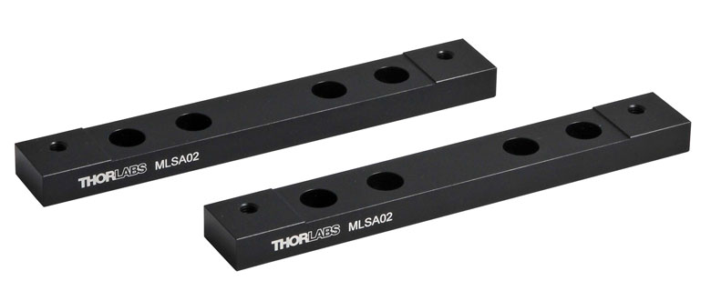
We offer a choice of brackets to facilitate mounting the MLS203-1 stage to a range of upright and inverted microscopes from Thorlabs, Nikon, and Olympus. Please see the table below for specific compatibility. We also offer brackets that allow the MLS203-1 stage to be attached to imperial or metric breadboards for home-built microscopes or general photonics applications.
Each bracket comes with instructions describing how to attach the stage to the microscope. Please note that the MLS203-2 is directly compatible with Zeiss Axio Observer and Axiovert 40 microscopes. Mounting brackets are not required.
| Click Image for Details |
 |
 |
 |
 |
 |
 |
 |
 |
| Bracket Item # | CSA1000 | MLSA02 | MLSA09 | MLSA08 | MLSA03 | MLSA06 | MLSA07 | MLSA01 |
| Microscope Brand | Thorlabs | Olympus | Nikon | Optical Breadboard, Custom Configuration |
||||
| Microscope Model | Cerna® | IX71, IX73, IX81, IX83 |
IX70 | BX41, BX43, BX51, BX53, BX61 |
TE2000, Eclipse Ti |
50i, 80i, 90i, Ci-L |
Eclipse FN1 | N/A |
| Microscope Type | Upright | Inverted | Inverted | Upright | Inverted | Upright | Upright | N/A |

Click to Enlarge
MLS203-1 Stage Attached to a Breadboard with our MLSA01 Bracket Set
| We support microscopes from Olympus, Nikon, Zeiss and Leica. Please contact Technical Support to inquire about bracket availability if your microscope model is not listed above. |

 Zoom
Zoom
Click to Enlarge
MZS500-E Z-Axis Piezo Stage Being Attached to the Motorized XY Scanning Stage

Click to Enlarge
MZS500-E Z-Axis Piezo Stage with Multiwell Plate Fitted
| Key Stage Specifications | |
|---|---|
| Travel Range | 500 µm |
| Resolution | 25 nm |
| Minimum Step Size | 250 nm (Typical) |
| Settling Time for 1 to 100 µm Step | 25 ms (Typical) |
- Includes the Z-Axis Piezo Stage and Controller
- Z-Axis Piezo Stage:
- Z-Axis Component of the Motorized XYZ Microscope Stage System
- Must First be Mounted to the MLS203 XY Stage (See Photo to Right)
- Accessories, Such as Sample Plates and MZF001 Joystick Control, are Sold Below
- Controller:
- Quiet, High-Resolution Position Control
- High Power: 150 V, 500 mA Continuous
- Full Software Control Suite Supplied
- Software Integrated with Other APT™ Family Controllers (Integrated Systems Development)
- Closed-Loop PID Position via Capacitive Feedback Circuit
- Voltage Ramp/Waveform Generating Capability
(for Scanning Applications) - User-Controlled Digital I/O Port
The MZS500-E Z-axis stage and controller bundle includes a Z-axis stage and a closed-loop piezo controller. The piezo-driven stage provides 500 µm of vertical (Z-axis) travel, 25 nm of resolution, and a 0.5 lb (0.25 kg) max load capacity. The bundle includes everything needed for computer-controlled, Z-axis positioning and active location feedback. Please see the Specs tab for more information on the Z-axis piezo stage.
To incorporate the Z-Axis Stage into a system, it must first be mounted to an MLS203 series XY stage (shown to the upper far right). These two products combined present a versatile 3D solution for translating samples over a long range or across a sample with high precision. The stage can also be directly fitted with a multiwell plate (shown to the upper right); additional accessories can be found below.
The controller included with the stage is a single-channel, high-power (150 V, 500 mA), benchtop piezo controller for open- and closed-loop nanometer position control. Flexible software settings make this controller suitable for driving a wide range of third-party piezo products. In addition, USB connectivity provides easy plug-and-play PC operation; multiple units can be connected to a single PC via a standard USB hub for multi-axis motion control applications. Coupling this with the user-friendly APT™ software allows the user to quickly get up and running. Advanced custom motion control applications and sequences are also possible using the extensive ActiveX® programming environment. These ActiveX Controls can be incorporated into a wide range of software development environments including Labview, C++, and Matlab. Please see the Specs tab for more information on the Z-axis stage controller.
MZS500P5 and MZS500P4 Breadboards
Click to Enlarge
- MZS500P5: 15 x 1/4"-20, 1" Pitch
- MZS500P4: 15 x M6, 25 mm Pitch
C4SH01 Multi Slide Holder
Click to Enlarge
- Plastic Holder Compatible with 25 mm x 75 mm, 1.1 ± 0.2 mm Thick Microscope Slides
- Does Not Hold 26 mm x 76 mm Slides Sold by Thorlabs
- Mount up to Four Slides for Automated Tissue and Tissue Microarray Analysis
- Same Footprint as Multiwell Plates (127.6 mm × 85.5 mm)
MZS500P2 Slide/Petri Dish Holder
Click to Enlarge
- Compatible with Microscope Slides Measuring 25 mm to 25.4 mm (0.98" to 1.0") in Width
- Compatible with Petri Dishes
- Does Not Hold 26 mm x 76 mm Slides Sold by Thorlabs
- Measuring 30 mm to 60 mm (1.18" to 2.36") in Diameter
- Can be Used with Imperial or Metric Accessories
MZS500P3 Blank Adapter Plate
Click to Enlarge
- Ideal for Custom Applications
- Easily Drilled and Tapped
Breadboard Plate Application
Click to Enlarge
MZS500P5 Mounted in the MZS500-E Z-Axis Stage
Multi Slide Holder Application
Click to Enlarge
C4SH01 Slide Holder Tray Mounted in the MZS500-E Z-Axis Stage
Slide/Petri Dish Application
Click to Enlarge
MZS500P2 Slide/Petri Dish Holder Mounted in the MZS500-E Z-Axis Stage with the Stage Micrometer
Blank Adapter Plate Application
Click to Enlarge
MZS500P3 Mounted in the MZS500-E Z-Axis Stage

 Zoom
Zoom- High Reliability Hall Effect Finger Joystick
- Speed Adjustment for Fast or High-Precision Moves
- Speed Dial for Sensitivity Adjustment
- Allows Remote Manual Control
- Can be Reprogrammed using a Benchtop Controller and a PC
- Ergonomic Design
- High-Quality Machined Anodized Aluminum Casing
The MZF001 joystick console has been designed for microscope users to provide intuitive, tactile, manual positioning of the MZS500 stage. It is used in conjunction with the MZS500-E controller above. Furthermore, if the parameter settings are saved (persisted) to the controller using a PC, the controller can be disconnected from the computer allowing for remote operation.

 Zoom
Zoom- Ideal for use with MLS203 Stages
- Speed Adjustment for Fast or High Precision Moves
- Speed Dial for Sensitivity Adjustment
- Ergonomic Design
- High-Quality Machined Anodized Aluminum Casing
- High-Reliability Hall Effect Joystick
The MJC001 Joystick Console has been designed for microscope users and provides intuitive, tactile, manual positioning of the MLS203 Stages and other XY translation stages. The console features a two-axis joystick for XY control. In most applications, the default parameter settings saved within the controller allow the joystick to be used out-of-the-box, with no need for further setup, thereby negating the requirement to be connected to a host PC and allowing true remote operation.
The MJC001 is compatible with our Benchtop Brushless Controllers, Rack-Mounted Brushless Controller, and Stepper Motor Controllers. The joystick is shipped complete with cables for use with these controllers. If you intend to use the joystick with a legacy BBD10x series unit, please contact Tech Support for a compatible cable.