 Products Home / Optical Elements / Test Targets, Calibration Targets, and Reticles / Grid Distortion Test Targets
Grid Distortion Test Targets
- Test Targets Help Identify Distortion in Imaging Systems
- Grid Spacings Available from 10 µm to 2000 µm
- Combined Resolution and Distortion Targets Available
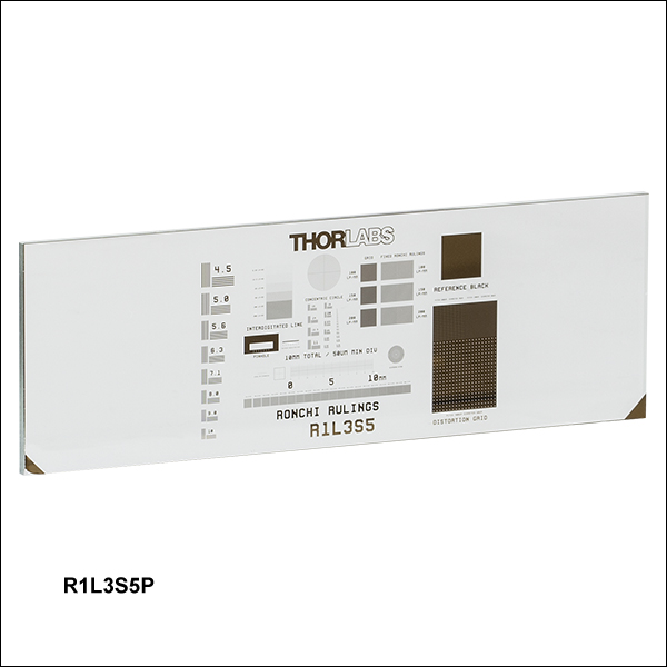
R1L3S5P
Combined Resolution and
Distortion Test Target
R1L3S3P
Multi-Frequency Grid
Distortion Target
R2L2S3P4
Fixed Frequency Grid
Distortion Target
R1L1S1N
Combined Resolution and
Distortion Test Target


Please Wait
| General Specifications | |
|---|---|
| Chrome Thickness | 0.120 µm |
| Chrome Optical Density | OD ≥3 at 430 nm |
| Substrate Thickness | 0.06" (1.5 mm) |
| Surface Flatness | ≤15 µm |
| Line Spacing Tolerancea | ±1 µm |
| Line Width Tolerancea | ±0.5 µm |
| Substrate | Sode Lime Glass |

Click to Enlarge
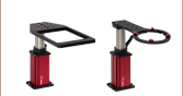
An R1L3S5P Combined Resolution and Distortion Test Target Mounted in an XYF1 Test Target Positioner
Features
- Fixed and Multi-Frequency Grid Distortion Test Targets
- Combined Resolution and Distortion Test Targets
- Distortion in Grid Image Allows for Image Correction
- Grids Available with Spacings of 10 µm to 2000 µm
Thorlabs offers a variety of options for measuring the distortion of an optical system including targets with a single-frequency grid, multi-frequency grids, or distortion grids alongside a wide variety of other patterns for resolution measurement, calibration, and more. Combined, these targets offer grid spacings ranging from 10 µm to 2000 µm.
Each target is made from a soda lime glass substrate with vacuum-sputtered, low-reflectivity chrome in patterns of either horizontal and vertical lines or rows and columns of solid circles. Each pattern is manufactured using photolithography, allowing for edge features to be resolved down to approximately 1 µm. Because the lines or rows and columns are perpendicular, they will be imaged as such by an ideal system. A distorted image will show the lines or rows and columns as bowed; this image allows the user to quantify the distortion and thus to correct for it using software built into programs such as LabVIEW or ImageJ.
Mounting
These distortion test targets can be mounted in one of four of our microscopy slide holders. Our MAX3SLH fixed slide holder provides two spring clips to mount the optic and can be mounted to any of our 3-axis translation stages; this slide holder is only compatible with test targets greater than or equal to 2" wide and provides a clear aperture of 1", which may cover the chrome pattern on some of the test targets. Thorlabs also offers our XYF1(/M) test target positioning mount (see photo above), which is capable of translating a 1" (25.4) to 3" (76.2 mm) wide rectangular target over a 50 mm (1.97") x 30 mm (1.18") area. The mount offers five 8-32 (M4) taps for six post-mountable orientations. The XYF1 uses nylon-tipped setscrews to secure the optic. Please note that the mount's support arms overlap the optic by 4.4 mm on each side. For users of the MLS203 microscopy stage, we offer the MLS203P2 slide holder for inverted microscopes, which can mount slides that measure 25 mm to 26.5 mm in width and petri dishes that measure 30 mm to 60 mm in diameter.
| Targets Selection Guide | |||
|---|---|---|---|
| Resolution Test Targets | Distortion Test Targets | Slant Edge MTF Resolution Test Targets | Calibration Targets |
| Posted Comments: | |
Konstantin Novoselov
(posted 2019-11-26 14:17:27.287) We need to produce optical calibration target to estimate/correct optical distortion in our instrument. This calibration target is similar your Grid Distortion Test Targets. In our case calibration pattern should be formed on the top of microscopic slide 25x50 mm 1.1 mm thickness. Calibration pattern consist of Ø150 µm dots arranged in a grid with spacing 200 µm.
Desired spacing and dot size tolerance is about 2-3 µm. Expected order quantity is 1-10 during prototyping stage and 100-1000 in production stage.
Can you please provide me with ballpark estimation of the manufacturing costs and lead times. llamb
(posted 2019-12-03 10:59:48.0) Thank you for contacting Thorlabs. For custom quotes, you may contact us at TechSupport@thorlabs.com by clicking the Request A Quote button above. I have reached out to you directly to discuss this particular case. dave.stubblefield
(posted 2017-02-23 07:04:15.327) Do you have any distortion targets that are designed for the IR spectrum? 3-5 micron and 8-12 micron. Maybe with a different substrate? Most transmission curves that I can find for soda lime glass do not extend into the IR region. tfrisch
(posted 2017-03-13 03:44:30.0) Hello, thank you for contacting Thorlabs. I will reach out to you directly about our custom capabilities for etching distortion targets. |

 Zoom
Zoom
Click to Enlarge
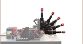
An R2L2S3P3 Target Post Mounted via an FFM1 Filter Mount and a B3C Cube Base for Use in a Custom Imaging System

Click to Enlarge
A Close Up of the Dot Pattern on the R2L2S3P4 Target
- One Grid Array on a 1.5" x 1.5" (38.1 mm x 38.1 mm) Soda Lime Glass Substrate
- 125 µm, 250 µm, 500 µm, or 1000 µm Grid Spacings
- Ø62.5 µm, Ø125 µm, Ø250 µm, or Ø500 µm Dots
- Ideal for Machine Vision Applications of Stage Calibration and Distortion Detection
These distortion grid arrays each feature a single grid of dots fabricated from the deposition of vacuum-sputtered, low-reflectivity chrome on a soda lime glass substrate. The available grid spacings, which are measured from the center of any dot to the center of any adjacent dot, range from 125 µm to 1000 µm, and the dot diameters range from 62.5 µm to 500 µm.
Grid arrays are used to determine the distortion of an imaging system. Ideally, the horizontal and vertical rows of dots should be perpendicular to each other. A distorted image will show the array as bowed; this image can then be used to correct for distortion.
| Item # | Spacinga | Spacing Tolerance |
Dot Size | Dot Size Tolerance |
Pattern Sizeb | Pattern Size Tolerance |
Pattern Optical Density |
Substrate Size |
|---|---|---|---|---|---|---|---|---|
| R2L2S3P1 | 125 µm | ±1 µm | Ø62.5 µm | ±2 µm | 25.0 mm x 25.0 mm (0.98" x 0.98") |
±4 µm | OD ≥3 at 430 nm | 1.5" x 1.5" x 0.06" (38.1 mm x 38.1 mm x 1.5 mm) |
| R2L2S3P2 | 250 µm | Ø125 µm | ||||||
| R2L2S3P3 | 500 µm | Ø250 µm | 25.4 mm x 25.4 mm (1" x 1") |
|||||
| R2L2S3P4 | 1000 µm | Ø500 µm |

 Zoom
Zoom
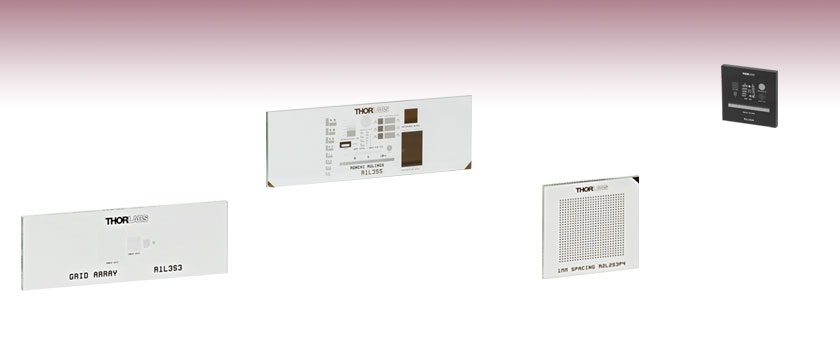
- Four Grid Arrays on a 3" x 1" (76.2 mm x 25.4 mm) Soda Lime Glass Slide
- 10 µm, 50 µm, 100 µm, and 500 µm Grid Spacings
- Ideal for Microscopy Applications of Stage Calibration and Distortion Detection
- Same Outer Dimensions as a Standard Microscope Slide
The R1L3S3P grid distortion target features four arrays of horizontal and vertical lines spaced 10 µm, 50 µm, 100 µm, and 500 µm apart. This pattern is fabricated from the deposition of vacuum-sputtered, low-reflectivity chrome with an optical density (OD) of ≥3 at 430 nm on a 3" x 1" x 0.06" (76.2 mm x 25.4 mm x 1.5 mm) soda lime glass substrate. The dimensions of the glass substrate are the same as a standard microscope slide.
Grid arrays are used to determine the distortion of an imaging system. Ideally, the horizontal and vertical lines of the grid should be perpendicular to each other. A distorted image will show the lines as bowed; this image can then be used to correct for distortion.

 Zoom
Zoom
Click to Enlarge
Close Up of the Smaller Grid on the R3L3S5P Target with Labels Added (See Tables Below)

- Concentric Circles and Crosshair Patterns Arranged in a Grid
- Four Different Concentric Circle Sizes and Five Different Crosshair Sizes
- Measure Resolution and Distortion of an Imaging System
- 3" x 3" (76.2 mm x 76.2 mm) Soda Lime Glass Substrate
Thorlabs' 3" x 3" (76.2 mm x 76.2 mm) Concentric Circle and Crosshair Grid Target offers 289 individual grids, arranged in a larger, 2" x 2" grid of 17 rows and 17 columns. The smaller grids each have four concentric circle patterns and five crosshair patterns of varying sizes. The concentric circle and crosshair patterns on the smaller grids are labeled in the image to the right but not on the target itself. Each concentric circle pattern features seven different radii, while the crosshairs each have a single or a double cross. For details on the dimensions of these patterns, see the tables below.
The pattern on this target is made from low-reflectivity, vacuum-sputtered chrome deposited on a 0.6" (1.5 mm) thick soda lime glass substrate to achieve an optical density of ≥3. The dark pattern and clear substrate are useful for front-lit and general applications.
| Concentric Circles | |||||||
|---|---|---|---|---|---|---|---|
| Circle Patterna | R1 | R2 | R3 | R4 | R5 | R6 | R7 |
| A1 | 31.3 µm | 62.5 µm | 125 µm | 140.6 µm | 234.4 µm | 242.2 µm | 500 µm |
| A2 | 15.6 µm | 31.3 µm | 62.5 µm | 70.3 µm | 117.2 µm | 121.1 µm | 250 µm |
| A3 | 7.8 µm | 15.6 µm | 31.3 µm | 35.2 µm | 58.6 µm | 60.5 µm | 125 µm |
| A4 | 3.9 µm | 7.8 µm | 15.6 µm | 17.6 µm | 29.3 µm | 30.3 µm | 62.5 µm |
| Crosshairs | |||
|---|---|---|---|
| Crosshair Patterna | Single or Double Line | Length/Width | Line Widthb |
| B1 | Double | 500 µm | 6.25 µm |
| B2 | Double | 500 µm | 12.5 µm |
| B3 | Single | 500 µm | 50 µm |
| B4 | Double | 500 µm | 25 µm |
| B5 | Double | 500 µm | 100 µm |

 Zoom
Zoom
- Determine Resolution of an Optical System
- Measure Image Distortion, Astigmatism, and Other Aberrations
- 18 mm (0.71") Square, 1.5 mm Thick Soda Lime Substrate
- Includes 1951 USAF Pattern, Sector Star, Concentric Circles, Grids, and Ronchi Rulings
- Positive and Negative Patterns Available
Thorlabs offers positive and negative 18 mm x 18 mm x 1.5 mm combined resolution / distortion test targets that are made by plating vacuum-sputtered, low-reflectivity chrome with an optical density (OD) of ≥3 at 430 nm on a soda lime glass substrate. They are ideal for calibration of imaging systems and microscope stages.
The test targets include a 1951 USAF pattern (Groups 2 - 7), a sector star, concentric circles, grids (100 µm, 50 µm, and 10 µm), and Ronchi rulings (30 - 150 lp/mm). These targets are useful for testing resolution, field distortion, focus errors, and astigmatism. The USAF 1951 targets are useful for measuring imaging resolution. The grids can be used to measure image distortion, while the concentric circles are ideal for identifying focus errors, astigmatism, and other aberrations existing in an imaging system. The Ronchi rulings are excellent for evaluating resolution, field distortion, and parfocal stability. For more information, please see our Resolution Targets page.
These resolution targets are offered in positive and negative versions. The R1L1S1P positive target consists of a chrome pattern plated on to a clear substrate and is useful for front-lit and general applications. Alternatively, the R1L1S1N negative target uses the same chrome coating to cover the substrate, leaving the pattern itself clear, and works well in back-lit and highly illuminated applications.
| Target Feature | Details | Target Feature | Details |
|---|---|---|---|
| 1951 USAF Target | Groups 2 - 7 | Concentric Circles | 10 Circles with Radii from 100 µm to 1000 µm in 100 µm Intervals, Labeled 1 to 10 |
| Grids | 20 x 20 Arrays with 100 µm, 50 µm, and 10 µm Pitch | Ronchi Rulings | 13 Rulings from 30 lp/mma to 150 lp/mm in 10 lp/mm Intervals |
| Sector Star | 36 Bars through 360°, 10 µm Radius Center Circle, and Ten Concentric Circles with Radii from 50 µm to 500 µm in 50 µm Intervals | ||

 Zoom
Zoom|
|
- 3" x 1" (76.2 mm x 25.4 mm) Soda Lime Substrate
- Includes NBS 1963A Pattern, Sector Star, Concentric Circles, Grids, Ronchi Rulings, and More (See Table Below)
- Determine Resolution of an Optical System
- Measure Image Distortion, Astigmatism, and Other Aberrations
- Compatible with our MLS203 Microscope Stages via MLS203P2 Slide Holder
Thorlabs offers positive 3" x 1" x 0.06" (76.2 mm x 25.4 mm x 1.5 mm) combined resolution / distortion test targets that are made by plating vacuum-sputtered, low-reflectivity chrome with an optical density (OD) of ≥3 at 430 nm on a soda lime glass substrate. They are ideal for calibration of imaging systems and microscope stages. They are sized to fit in our MLS203P2 stage slide holder for use with our MLS203 microscope stages.
The test targets include an NBS 1963A pattern, a sector (Siemens) star, concentric circles, grids, Ronchi rulings, and more (see table below). These targets are useful for testing resolution, field distortion, focus errors, and astigmatism. The NBS 1963A, sector star, and concentric circle targets are useful for measuring imaging resolution. The grids can be used to measure the distortion introduced by an imaging system. The Ronchi rulings are excellent for evaluating resolution, field distortion, and parfocal stability. For more information, please see our Resolution Targets page.
| Target Feature | Details | Target Feature | Details |
|---|---|---|---|
| NBS 1963A | Frequencies from 4.5 cycles/mm to 228 cycles/mm (See List Above) | Concentric Circles | 10 Circles with Radii from 100 µm to 1000 µm in 100 µm Intervals |
| Distortion Grid (Squares) | 3 Grids: 100 lp/mma, 150 lp/mm, 200 lp/mm | Fixed Ronchi Rulings | 3 Rulings:100 lp/mm, 150 lp/mm, and 200 lp/mm |
| Distortion Grid (Dots) | 3 Grids: 400 µm Pitch of Ø80 µm Dots, 200 µm Pitch of Ø 40 µm Dots, 100 µm Pitch of Ø20 µm Dots |
Variable Ronchi Rulings | 20 Rulings (Each 1 mm x 1 mm): 10 lp/mm to 200 lp/mm in 10 lp/mm Intervals |
| Two-Point Resolution Dots | Ø25 µm, Ø20 µm, Ø15 µm, Ø12.5 µm, Ø10 µm, Ø7.5 µm, and Ø5 µm | Pinholes | Ø25 µm, Ø20 µm, Ø15 µm, Ø12.5 µm, Ø10 µm, Ø7.5 µm, and Ø5 µm |
| Interdigitated Lines | 6.25 lp/mm, 12.5 lp/mm, 25 lp/mm, 50 lp/mm, 100 lp/mm, and 200 lp/mm | Micrometers | 3 Rulers: 10 mm Scale with 50 µm Divs, 1 mm Scale with 10 µm Divs, and 1mm x 1 mm XY Scale with 50 µm Divs |
| Sector Star | 36 Bars through 360°, 50 µm Radius Center Circle, and Ten Concentric Circles with Radii from 100 µm to 500 µm in 50 µm Intervals | ||