 Products Home / Motorized Stages / Linear Long Travel (>100 mm) Motorized Stages / 220 mm Linear Translation Stage, Direct-Drive Servo Motor
220 mm Linear Translation Stage, Direct-Drive Servo Motor
- 220 mm Travel at Speeds up to 300 mm/s
- Brushless DC Servo Motors
- Direct Drive - No Leadscrew
XY Configurable
DDS220
Application Example
Our ODL220 Optical Delay Line Kit
Incorporates Our DDS220 Stage


Please Wait
| Key Specificationsa | |
|---|---|
| Travel Range | 220 mm (8.6") |
| Velocity (Max) | 300 mm/s |
| Min Achievable Incremental Movement | 0.1 µm |
| Bidirectional Repeatabilityb | ±0.25 µm |
| Horizontal Load Capacity (Max) | 3.0 kg (6.6 lbs) |
| Actuator Type | Brushless DC Servo Motor |
| Cable Length | 2.7 m (8.9 ft) |
| Recommended Controller | apt™ Servo Motor Controllers |
| Motorized Linear Long-Travel Stages | |
|---|---|
| 100 mm | Stepper |
| 150 mm | Stepper |
| Stepper with Integrated Controller | |
| 220 mm | DC Servo |
| 300 mm | Stepper with Integrated Controller |
| DC Servo with Benchtop Controller | |
| 600 mm | DC Servo with Benchtop Controller |
| Optical Delay Line Kits | |
| Other Translation Stages | |
Features
- High Speeds: Up To 300 mm/s
- High Repeatability: 0.25 µm
- Positional Accuracy: <3.0 µm
- Low Profile: 44 mm (1.73")
- Integrated, Brushless DC Linear Servo Motor Actuators
- Linear Optical Encoders
- High-Quality, Precision-Engineered Linear Bearings
- 4-40, 8-32, and 1/4"-20 or M3, M4, and M6 Tapped Holes for Mounting Optomechanics
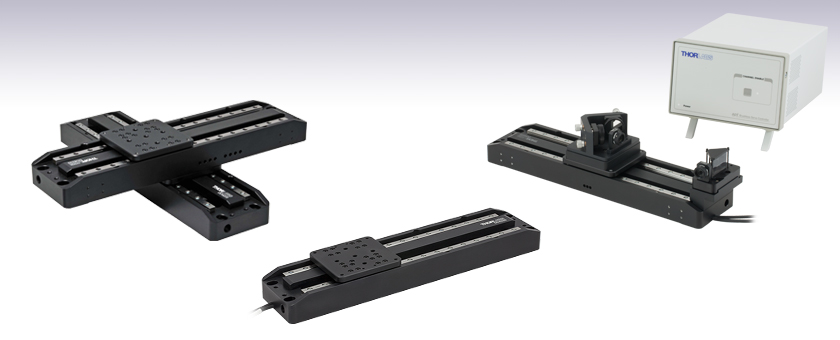
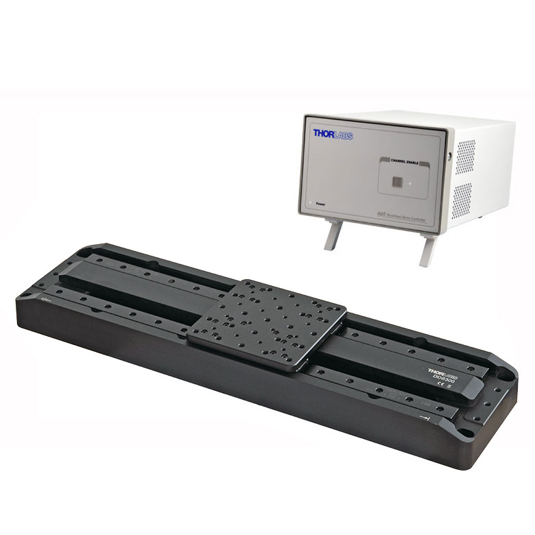
Thorlabs' DDS220 low-profile, direct-drive translation stage provides 220 mm of travel with 50 nm resolution and a maximum speed of 300 mm/s. This stage is ideal for applications that require high speeds and high positioning accuracy, including automated alignment, surface inspection, mapping, and probing.
An innovative, low-profile design with integrated, brushless linear motors eliminates the external housings that create mechanical clash points and impede access to the moving platform. The direct-drive technology removes the need for a lead screw, eliminating backlash and internal flexible ducting ensures cables cannot become trapped as the mechanism moves. Twin, precision-grooved linear bearings provide superior rigidity and linearity with excellent on-axis accuracy. This backlash-free operation coupled with high-resolution, closed-loop optical feedback ensures a minimal bidirectional repeatability of ±0.25 μm. The DDS220 stage is at the core of our ODL220 Optical Delay Line kit.


Dual-Axis Configuration
For dual-axis applications, two stages can be directly bolted together in an XY configuration without the need for an adapter or spacer plate, thereby keeping the vertical profile to a minimum. Furthermore, end users can choose to bolt the upper stage on centrally (as shown at the top of the page) or off center (as shown to the left).
Please note that these stages are not suitable for operation in a vertical (Z-axis) orientation.
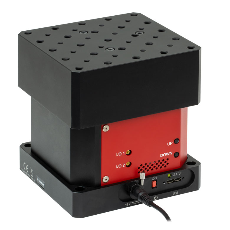
Controller Options
The recommended controller for the DDS220 direct-drive, linear translation stage is the BBD201 single-axis or BBD202 dual-axis Brushless DC Motor Controller. These controllers provide a user-configurable, S-curve acceleration/deceleration profile that enables fast, smooth positioning without vibration or shock. See below for a brief overview, or click here to view the full presentation for these Brushless DC Motor Controllers.
Joystick Option
An optional 2-axis joystick console (MJC001) is also available for remote positioning applications. See the presentation below for more details.
Accessory Mounting Plates
A range of mounting plates is also available. The DDSA01 and DDSA02 adapter plates allow accessories to be fixed to the moving platform, or either end of the stage. The DDS220P1 allows a NanoMax or MicroBlock stage to be bolted to the moving platform of the DDS220 stage. See the presentations below for more details.
| DDS220 Stage | |
|---|---|
| Travel Range | 220 mm (8.6") |
| Speed (Max) | 300 mm/s |
| Acceleration (Max) | 5000 mm/s2 |
| Bidirectional Repeatabilitya | ±0.25 µm |
| Backlashb | N/A |
| Load Capacityc | 3.0 kg (6.6 lb) |
| Incremental Movement (Min)d | 0.1 µm |
| Absolute On-Axis Accuracy | ±2.0 µm |
| Home Location Accuracy (Unidirectional) | ±0.25 µm |
| Straightness | ± 5.0 µm |
| Pitche | ±175 µrad |
| Yawe | ±175 µrad |
| Continuous Motor Force | 7.0 N |
| Peak Motor Force (2 sec) | 15 N |
| Weight (Including Cables) | 2.4 kg (5.3 lbs) |
| Limit Switches | Yes |
| Operating Temperature Range | 5 to 40 °C (41 to 104 °F) |
| Bearing Type | Precision Linear Bearing |
| Motor Type | Brushless DC Linear Motor |
| Dimensions | 370.0 mm x 90.0 mm x 44.0 mm (14.57" x 3.54" x 1.73") |
| Weight | 2.4 kg (5.3 lbs) |
| Recommended Controller | BBD201 (1-Channel) BBD202 (2-Channel) |
| BBD201 Controller | |
|---|---|
| Drive Connector | 8-Pin DIN, Round, Female |
| Feedback Connector | 15-Pin D-Type |
| Continuous Drive Output | 5 A |
| PWM Frequency | 40 kHz |
| Operating Modes | Position and Velocity |
| Control Algorithm | 16-Bit Digital PID Servo Loop with Velocity and Acceleration Feedforward |
| Velocity Profile | Trapezoidal/S-Curve |
| Position Count | 32 Bit |
| Position Feedback | Incremental Encoder |
| Encoder Bandwidth | 2.5 MHz 10 M Counts/s |
| Encoder Supply | 5 V |
| AUX Control Connector | 15-Pin D-Type |
| Power Supply Input | Power: 250 VA Voltage: 85 to 264 VAC Frequency: 46 to 63 Hz Fuse: 3.15 A |
| Dimensions | 240 mm x 337.9 mm x 124.8 mm (9.5" x 13.3" x 4.9") |
| Weight | 3.46 kg (7.6 lbs) |
The flying leads are terminated in a male 15-pin D-Type and male 8-pin round DIN connector. Pin details are given below.
Feedback Connector

Motor Drive Connector

| Pin | Description | Pin | Description |
|---|---|---|---|
| 1 | Not Used | 9 | Ground |
| 2 | Ground | 10 | Limit Switch + |
| 3 | Not Used | 11 | Limit Switch - |
| 4 | Enc Index - | 12 | Enc Index + |
| 5 | QB - | 13 | QB + |
| 6 | QA - | 14 | QA + |
| 7* | 5 V | 15 | Not Used |
| 8* | 5 V |
*Pins 7 and 8 are shorted together internally
| Pin | Description |
|---|---|
| 1 | Motor Phase V |
| 2 | Ground |
| 3 | Thermistor (Not Used) |
| 4 | Motor Phase U |
| 5 | Stage ID |
| 6 | Ground |
| 7 | Motor Phase W |
| 8 | Enable |
| Posted Comments: | |
KC Woo
(posted 2019-08-02 04:07:36.613) Hi. I've been using DDS220 & BBD201 for years, and recently I've got some troubles while attempting to access the encoder functions with LabView control. Since it is written with 'linear optical encoders' in the specification, I expected that my device would work with rapid scanning (as in doi: 10.1063/1.3455809). However, I've faced with the error messages with code# 13021512 (Description: Encoder Not Found) (Notes: An attempt has been made to access encoder functionality when no encoded stage/actuator has been associated with this channel.), when I tried with the Invoke Node with the encoder methods such as 'CalibrateEnc'. Could you give me any advice on this problem. Thanks in advance. rmiron
(posted 2019-08-06 04:30:05.0) Response from Radu at Thorlabs: It is difficult to tell why this error is being raised without seeing your virtual instrument. I will contact you directly in order to troubleshoot your application. adri-vlc96
(posted 2018-04-16 12:23:41.867) Hi
I'm studying a cryogenic 3d printer which is using the motor DDS220/M, and with temperatures between -5 and -15 ºÇ the tolerances get bigger.
I understand that the ideal range is beetween 5 and 40ºÇ but which part of the motor work worse when the temperatures go down? Or maybe it is related with the decrease of the resistance of the cooper?
Thanks for your time. bhallewell
(posted 2018-05-15 08:32:57.0) Response from Ben at Thorlabs: Thank you for your email here. You will find on our website that the majority of our stages are rated at 5-40degC. Below 5degC, the greatest problem would be the build up of condensation which can potentially lead to a short within the hardware electronics. Jane.Yang
(posted 2017-09-29 17:14:38.563) What's the minimal velocity for this stage - smooth moving without "vibration" at low speed?
Thanks! bwood
(posted 2017-10-06 04:00:04.0) Response from Ben at Thorlabs: Thank you for your feedback, unfortunately it's hard to define a minimum velocity as it will be highly application specific. All brushless DC motor stages work based on a servo mechanism, (i.e. error feedback via an encoder), which needs to have certain level of velocity fluctuations when the stage is demanded to perform a constant speed in its sequence. This is due to the nature of the closed loop algorithm in the controller, which is in opposition to the resultant resistive force of the bearing carriage/rail, magnetic flux density fluctuations of the magnet rod (at various positions) and so on. The position loop PID algorithm needs to continuously overshoot and undershoot in following the demanded constant speed according to the feedback position error. As such we do not have any firm real world values as the PID parameters can be tuned for a specific application. arkadiusz.jarota
(posted 2017-03-30 08:08:44.583) Dear Thorlabs,
Do you have Labview drivers for DDS220/M delay stage for 64-bit Windows 10. We have drivers for 32 bit systems, but these are not working.
Best Regards,
Arkadiusz Jarota bwood
(posted 2017-03-30 11:52:30.0) Response from Ben at Thorlabs: Thank you for your question. The files required to operate the DDS220/M with LabView are included with Kinesis, our motion control software. As long as you have downloaded 64bit version of Kinesis, the files should be available. user
(posted 2016-05-10 12:38:19.193) What is the meaning of the pitch and yaw values? Is it wobbling if the load changes, is it a change of angle over the whole length of the stage, or is it just an initial error?
For example, if we use two 220mm stages in an x-y-configuration, the top stage positioned at an end, then the error of +-175µrad of the bottom stage would result in an error of +-19µm on the top platform. It would make a big difference if this is all wobbling or just an initial error. bhallewell
(posted 2016-05-12 03:29:02.0) Response from Ben at Thorlabs: Thank you for your question here. We define the pitch as how much the top plate tilts as the stage translates. Pitch is measured by moving the stage over its full travel range and taking an angular robust laser interferometry (RLI) measurement in the pitch axis at 20 equidistant points along the travel. This is repeated 10 times and the maximum discrepancy between minimum and maximum value taken. Yaw is measured using the same procedure.
We specify our Pitch/Yaw values assuming the stage is bolted to an optical table surface in a single axis configuration with a nominal torque of 70N.cm per screw. When mounted in XY, the torque of the bolt screws can either cause freedom of movement from the top plate contributing to system wobble or deflection of the stage due to over-tightening. The bearing rail/carriages are preloaded however heavier loads can increase this effect. I will contact you directly to discuss this further.
If you are considering purchase of a new XY stage assembly I would advise also taking a look at our DDS300-E option as this employs a stiffer bearing set & housings, with wider paired bearing ways when compared to the 220mm range.
http://www.thorlabs.de/newgrouppage9.cfm?objectgroup_ID=7975&pn=DDS300-E szwackerow
(posted 2016-04-25 12:52:13.64) The download link for the controller software for 32bit Windows does not work. Could you send me a working link? besembeson
(posted 2016-04-25 09:32:05.0) Response from Bweh at Thorlabs USA: The control software for these stage are available at the following link: http://www.thorlabs.com/software_pages/ViewSoftwarePage.cfm?Code=Motion_Control&viewtab=0. We will contact you to determine which link you used that wasn't active. johan.stigwall
(posted 2015-11-18 09:09:01.3) The pitch/yaw specs of the DDS220 is +- 0.01 degree which is equal to 175 µrad. The DDS300 on the other hand is specified as 100/150 µrad. Is the DDS300 really better in pitch/yaw, or is this difference only due to rounding error?
Another question: Is it possible to buy the DDS300 without controller and drive one DDS300 + one DDS220 using a two-channel BBD202 controller? msoulby
(posted 2015-11-18 06:04:36.0) Response from Mike at Thorlabs: The DDS300 is an updated version of the older DDS220, and thus the pitch and yaw specs have been improved. The BBD202 controller can control both a DDS220 and DDS300 on the separate channels. We will contact you directly with a quotation for only the DDS300 stage without the controller. dasaerod
(posted 2014-05-13 13:26:54.687) Dear Sir/Madam,
I am writing to you because I am considering to buy one of your translation stage (DDS220/M) to use for fibre bragg grating inscription. Once I read the characteristics some question has arisen to me.
First, I would like to know if this translation stage is able to work at speeds of 1 micron/s or less and what is the velocity error.
Second, I would like to know what is the exact meaning of flatness. In this case there are a variation of 5 microns, it means that the height of the stage can vary 5 microns during the whole travel (from 0 to 220 mm) or it is an oscillation of the height during the travel?
Best regards,
Dr David Saez Rodriguez bhallewell
(posted 2014-05-19 10:04:33.0) Response from Ben at Thorlabs: Thank you for your email & web feedback post. The DDS220/M contains a brushless DC servo motor which is optimised for precision motion at high acceleration & velocity through a PID closed-loop algorithm. This form of control will provide fluctuating motion at these low speeds. A piezo solution such as our NFL5DP20S/M platform would be more suitable for your low velocity requirement however would be limited in travel range. With regards to flatness, this is the vertical shift in the position of a single point on the top plate when the stage travels from 0 to 220mm. pascal.dufour
(posted 2013-04-03 14:57:33.34) What is the operating temperature range of the DDS220? tcohen
(posted 2013-04-04 12:29:00.0) Response from Tim at Thorlabs: We recommend using this stage within the temperature range of 5-40C. jlow
(posted 2012-10-10 17:00:00.0) Response from Jeremy at Thorlabs: The load capacity of the stage is dependent on the acceleration. If you lowered the acceleration by half, the load capacity will increase by two times. For example, if you set the acceleration of the bottom DDS220 to 2500mm/s^2, then you can put a maximum load of 3.6kg on the top DDS220. mingsong.chen
(posted 2012-10-09 12:16:25.0) Hello, for Dual-Axis Configuration of DDS220, what is the load capacity? I noticed that the load capacity for single DDS220 is 3kg, and the weight of DDS220 is 2.4kg, can I say that the load capacity of dual-axis of DDS220 (two DDS220) is (3-2.4)=0.6kg? Thanks. bdada
(posted 2011-11-03 10:20:00.0) Response from Buki at Thorlabs:
Thank you for participating in our Feedback forum. The DDS220/M stage does not work in environments up to 180 degrees Celcius and we do not recommend using it in a dusty environment. We will contact you to learn more about your application in order to recommend a more suitable product. a.lodermeyer.stud
(posted 2011-11-03 13:39:37.0) Dear Sir or Madam,
I've got two questions on your product DDS220/M:
1. Does it work at a temperature of around 180°C?
2. Does it word in dusty conditions? (i.e. when powder is in the working area of the linear stage)
Thank you very much for your support!
Best regards,
Alexander Lodermeyer
Bayerisches Laserzentrum, Erlangen, Germany |
Motorized Linear Translation Stages
Thorlabs' motorized linear translation stages are offered in a range of maximum travel distances, from a stage with 20 µm of piezo translation to our 600 mm direct drive stage. Many of these stages can be assembled in multi-axis configurations, providing XY or XYZ translation. For fiber coupling applications, please see our multi-axis stages, which offer finer adjustment than our standard motorized translation stages. In addition to motorized linear translation stages, we offer motorized rotation stages, pitch and yaw platforms, and goniometers. We also offer manual translation stages.
Piezo Stages
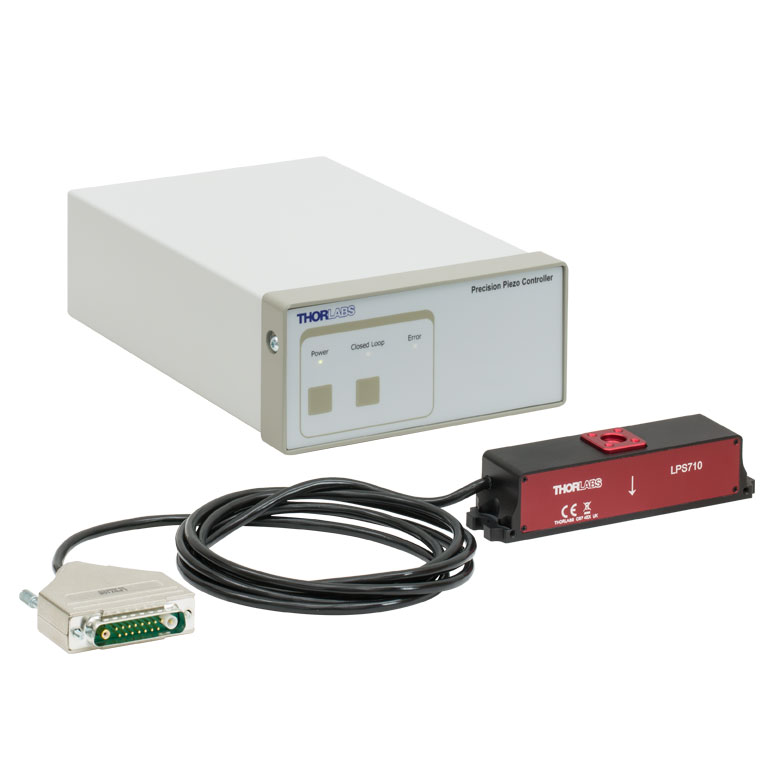
These stages incorporate piezoelectric elements in a variety of drive mechanisms. Our Nanoflex™ translation stages use standard piezo chips along with manual actuators. Our LPS710E z-axis stage features a mechanically amplified piezo design and includes a matched controller. The PD1 stage incorporates a piezo inertia drive that uses "stick-slip" friction properties to obtain an extended travel range. The Elliptec™ stages use resonant piezo motors to push and pull the moving platform through resonant elliptical motion.
| Piezoelectric Stages | ||||||
|---|---|---|---|---|---|---|
| Product Family | Nanoflex™ 20 µm Stage with 5 mm Actuator |
Nanoflex™ 25 µm Stage with 1.5 mm Actuator |
LPS710E 1.1 mm Z-Axis Stage |
PD1 20 mm Stage | Elliptec™ 28 mm Stage | Elliptec™ 60 mm Stage |
| Click Photo to Enlarge |
 |
 |
 |
 |
 |
 |
| Travel | 20 µm + 5 mm Manual | 25 µm + 1.5 mm Manual | 1.1 mm | 20 mm | 28 mm | 60.0 mm |
| Maximum Velocity | - | - | 3 mm/s | 180 mm/s | 90 mm/s | |
| Drive Type | Piezo with Manual Actuator | Amplified Piezo | Piezoelectric Inertia Drive | Resonant Piezoelectric Motor | ||
| Possible Axis Configurations |
X, XY, XYZ | - | X, XY, XYZ | X | ||
| Additional Details | ||||||
Stepper Motor Stages
These translation stages feature removable or integrated stepper motors and long travel ranges up to 300 mm. The MLJ150 stage also offers high load capacity vertical translation. The other stages can be assembled into multi-axis configurations.
| Stepper Motor Stages | |||||||
|---|---|---|---|---|---|---|---|
| Product Family | LNR Series 25 mm Stage |
LNR Series 50 mm Stage |
MLJ150 50 mm Vertical Stage |
NRT Series 100 mm Stage |
NRT Series 150 mm Stage |
LTS Series 150 mm Stage |
LTS Series 300 mm Stage |
| Click Photo to Enlarge |
 |
 |
 |
 |
 |
 |
 |
| Travel | 25 mm | 50 mm | 50 mm | 100 mm | 150 mm | 150 mm | 300 mm |
| Maximum Velocity | 2.0 mm/s | 50 mm/s | 3.0 mm/s | 30 mm/s | 50 mm/s | ||
| Possible Axis Configurations |
X, XY, XYZ | X, XY, XYZ | - | X, XY, XYZ | X, XY, XYZ | ||
| Additional Details | |||||||
DC Servo Motor Stages
Thorlabs offers linear translation stages with removable or integrated DC servo motors. These stages feature low profiles and can be assembled in multi-axis configurations.
| DC Servo Motor Stages | |||||
|---|---|---|---|---|---|
| Product Family | MT Series 12 mm Stages | PT Series 25 mm Stages | MTS Series 25 mm Stage | MTS Series 50 mm Stage | KVS30 30 mm Vertical Stage |
| Click Photo to Enlarge |  |
 |
 |
 |
 |
| Travel | 12 mm | 25 mm | 25 mm | 50 mm | 30 mm |
| Maximum Velocity | 2.6 mm/s | 2.4 mm/s | 8.0 mm/s | ||
| Possible Axis Configurations | X, XY, XYZ | X, XY, XYZ | - | ||
| Additional Details | |||||
Direct Drive Stages
These low-profile stages feature integrated brushless DC servo motors for high speed translation with zero backlash. When no power is applied, the platforms of these stages have very little inertia and are virtually free running. Hence these stages may not be suitable for applications where the stage's platform needs to remain in a set position when the power is off. We do not recommend mounting these stages vertically.
| Direct Drive Stages | |||
|---|---|---|---|
| Product Family | DDS Series 220 mm Stage |
DDS Series 300 mm Stage |
DDS Series 600 mm Stage |
| Click Photo to Enlarge |  |
 |
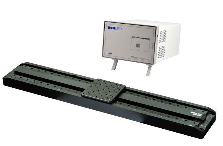 |
| Travel | 220 mm | 300 mm | 600 mm |
| Maximum Velocity | 300 mm/s | 400 mm/s | 400 mm/s |
| Possible Axis Configurations | X, XY | X | X |
| Additional Details | |||

 Zoom
ZoomCharacterized by high-speed translation and high-positional accuracy, the DDS220 stage is well-suited for surface mapping and characterization applications where there is a need to move a camera or probe at constant velocity while simultaneously capturing data. Very precise, fine positioning and control is easily achieved through a combination of the stable closed-loop control system and a BBD series controller with associated MJC001 joystick option (described below).

 Zoom
Zoom- High-Reliability Hall Effect Joystick
- Speed Adjustment for Fast or High Precision Moves
- Speed Dial for Sensitivity Adjustment
- Ergonomic and Elegant Design
- High-Quality Machined Anodized Aluminum Casing
The MJC001 joystick console has been designed to provide intuitive, tactile, manual positioning of a stage. The console features a two-axis joystick for XY control. In most applications, the default parameter settings saved within the controller allow the joystick to be used out-of-the-box, with no need for further setup, thereby eliminating the need to be connected to a host PC and allowing true remote operation. This joystick is compatible with our Benchtop Brushless Controllers, Rack-Mounted Brushless Controller, and Stepper Motor Controllers.

 Zoom
Zoom
- Single Plate to Mount MicroBlock or NanoMax Directly to the DDS220 Stage
- Resulting Overall Deck Height: 112.5 mm
- Resulting Overall Optical Height: 125.0 mm
- Bolts Supplied for Mounting to DDS220 Stage
This mounting plate enables our MAX300 and MBT61x series of 3-axis stages to be mounted on the DDS220 stage.
The 3-axis stage can be positioned quickly by the DDS220, before the MBT/MAX micrometer drives are used for fine manipulation of the device.

 Zoom
Zoom Click to Enlarge
 DDS220 stage with DDSA01 end mounting plates fitted
 Click to Enlarge
 DDS220 stage with DDSA01 end mounting plates and DDSA02 grooved mounting plates fitted
- End Mounting Plates with Nine 1/4"-20 (M6) Mounting Holes to Fix Accessories at Either End of Travel
- Grooved Mounting Plate with Sixteen 1/4"-20 (M6) Mounting Holes
- DDSA02(/M) Compatible with Flexure Stage Accessories
Two accessory plates are offered for use with the DDS220 Direct Drive Stage featured above. The DDSA01(/M) Mounting Plate bolts to either end of the stage using two user-supplied 1/4"-20 (M6) bolts and allows accessories to be fixed at either end of travel.
A second accessory plate, the DDSA02(/M) Grooved Mounting Plate, can be attached to the moving platform of the direct drive stage using the four included 1/4"-20 (M6) bolts. This plate features an array of sixteen 1/4"-20 (M6) mounting holes and a standard 3 mm groove. The DDSA02(/M) has sixteen 6-32 (M3) taps that can be used to mount flexure stage accessories via mounting cleats. When used in conjunction with a DDSA01(/M) End Mounting Plate, the DDSA02(/M) grooved mounting plate can also be used at either end of the stage travel and is ideal for optical delay line applications.