 Products Home
Motorized Pitch and Yaw Platform
- Low Profile: 25 mm (0.98") Platform Height
- ±2.5º Pitch and ±4.0º Yaw
- Load Capacity: 2.0 kg (4.40 lbs)
- DC Servo Actuators
PY004Z8
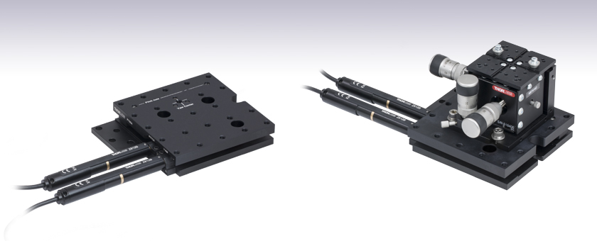
High-Load Pitch and Yaw Stage with DC Servo Actuators
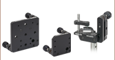
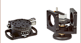
Application Idea
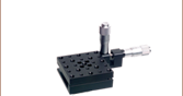
3-Axis Flexure Stage Mounted Directly to a PY004Z8 High-Load Pitch and Yaw Stage for High-Precision 5-Axis Control


Please Wait
| Key Specificationsa | ||
|---|---|---|
| Adjustment Range | Pitch: ±2.5° Yaw: ±4.0° |
|
| Minimum Achievable Incremental Movement |
Pitch: 7.13 arcsec Yaw: 15.71 arcsec |
|
| Bidirectional Repeatability | Pitch: 27.85 arcsec Yaw: 4.75 arcsec |
|
| Crosstalk | <0.05° (180 arcsec) | |
| Maximum Horizontal Load Capacityb |
2.0 kg (4.40 lbs) | |
| Maximum Vertical Load Capacityc |
Load Distance from Top Platform |
Max Load |
| 30 mm (1.18") | 1.8 kg (4.0 lbs) | |
| 50 mm (1.97") | 1.1 kg (2.4 lbs) | |
| 80 mm (3.15") | 0.7 kg (1.5 lbs) | |
| Deck Height | 25 mm (0.98") | |
| Bushing Diameter | 9.5 mm (3/8") | |
| Included Drives | Z812B DC Servo Motors (Qty. 2) | |

Click to Enlarge
K-Cube™ DC Servo Motor Controller (Two Required)
Features
- Motorized Pitch and Yaw Adjustment via Included DC Servo Actuators
- 1/4"-20 (M6) Tapped Holes with 1.00" (25.0 mm) Spacing
- Add Rotational Degrees of Freedom to Linear Stages
- 25.0 mm (0.98") Deck Height
- Black-Anodized Aluminum Construction
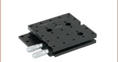
This Motorized Pitch and Yaw Platform provides ±2.5° of adjustment in pitch and ±4.0° in yaw. It is designed for use with loads up to 2.0 kg (4.40 lbs), such as lasers, cameras, and 3-axis stages. The actual maximum load will depend on the positioning of the load on the platform (see the table to the right or the Specs tab for more details). The 112.0 mm x 115.0 mm (4.41" x 4.53") top platform is equipped with an array of 1/4"-20 (M6) threaded mounting holes on 1" (25 mm) centers.
The base of the pitch and yaw platform is provided with eight through holes for attachment to metric or imperial optical tables and breadboards. The through holes allow the tapped holes on the unit to be in line with the optical table hole pattern or midway off the optical table hole pattern. The unit can also be secured at any arbitrary position by using two CL6 table clamps (sold separately).

Click to Enlarge
Engravings on the platform indicate the pitch axis and yaw center to help minimize crosstalk.
Included and Compatible Actuators
The two included Z812B DC servo actuators feature a 0.5 m
(1.6') cable length. They provide a minimum achievable incremental movement of 7.13 arcseconds in pitch and 15.71 arcseconds in yaw. The actuators attach to the stage using a flexure clamp that tightens around the Ø9.5 mm (Ø3/8") barrel. If desired, the Z812B actuator can be replaced by any manual or motorized 13 mm (0.47") actuator that includes a Ø9.5 mm (Ø3/8") barrel, including stepper motor actuators and manual micrometers.
Controller Options
Thorlabs recommends using two KDC101 T-Cube™ Motor Controllers, available below. Each KDC101 provides control for a single axis, with or without a PC. It is compatible with Thorlabs' APT™ software, which supplies out-of-the-box stage control from a PC and enables support for common programming interfaces like LabVIEW, LabWindows, and ActiveX. A USB cable is included with each KDC101. For more information or to download our APT™ software, please see the APT Software and APT Tutorials tabs.
PY004Z8(/M) Specifications
| Specification | Value | |
|---|---|---|
| Pitch and Yaw Adjustment | ||
| Adjustment Range | Pitch: ±2.5° Yaw: ±4.0° |
|
| Minimum Achievable Incremental Movement |
Pitch: 7.13 arcsec Yaw: 15.71 arcsec |
|
| Bidirectional Repeatability | Pitch: 27.84 arcsec Yaw: 4.74 arcsec |
|
| Maximum Velocity | Pitch: 1781 arcsec/s Yaw: 3142 arcsec/s |
|
| Maximum Acceleration | Pitch: 1781 arcsec/s2 Yaw: 3142 arcsec/s2 |
|
| Crosstalk | <0.05° (180 arcsec) | |
| Stage | ||
| Maximum Horizontal Load Capacitya | 2.0 kg (4.40 lbs) | |
| Maximum Vertical Load Capacityb | Load Distance from Top Platform |
Max Load |
| 30 mm (1.18") | 1.8 kg (4.0 lbs) | |
| 50 mm (1.97") | 1.1 kg (2.4 lbs) | |
| 80 mm (3.15") | 0.7 kg (1.5 lbs) | |
| Deck Height | 25 mm (0.98") | |
| Bushing Diameter | 9.5 mm (3/8") | |
| Body Construction | Black-Anodized Aluminum | |
| Actuator | ||
| Included Drive | Z812B | |
| Motor Type | DC Servo Motor | |
| Backlash | <8 µm | |
| Phase to Phase Resistance | 33.0 Ω (Max) | |
| Phase to Phase Inductance | 0.6 mH (Max) | |
| Calculated Minimum Achievable Incremental Movement | 0.05 µm | |
| Operating Temperature Range | 41° to 104° F (5° to 40° C) |
|
| Cable Length | 0.5 m (1.6') | |
| Connector | D-Type Male | |
| Compatible Controller | KDC101 | |
| Physical | ||
| Dimensions (L x W x H)c | 9.10" x 4.53" x 0.98" (231.0 mm x 115.0 mm x 25.0 mm) |
|
| Weight | 0.87 kg (1.92 lbs) | |
How to Calculate the Linear Displacement per Encoder Count
For the Z812B, there are 512 encoder counts per revolution of the motor. The output shaft of the motor goes into a 67:1 planetary gear head. This requires the motor to rotate 67 times to rotate the 1.0 mm pitch lead screw one revolution. The end result is the lead screw advances by 1.0 mm.
The linear displacement of the actuator per encoder count is given by
512 x 67 = 34,304 encoder counts per revolution of the lead screw,
whereas the linear displacement of the lead screw per encoder count is given by
1.0 mm / 34,304 counts = 2.9 x 10⁻⁵ mm (29 nm).
Horizontal Load Capacity Diagram

Diagram showing the two areas where the maximum load capacity
will change on the PY004Z8(/M)
Z812B Connector Pin Out
D-Type Male

| Pin | Description | Pin | Description |
|---|---|---|---|
| 1 | Ground (Limit and Vcc) | 8 | Reserved for Future Use |
| 2 | Forward Limit | 9 | Ident Resistor |
| 3 | Reverse Limit | 10 | Vcc (5 V DC) |
| 4 | Reserved For Future Use | 11 | Encoder Channel A |
| 5 | Motor (-) | 12 | Reserved for Future Use |
| 6 | Reserved For Future Use | 13 | Encoder Channel B |
| 7 | Motor (+) | 14, 15 | Reserved for Future Use |
The APT™ (Advanced Positioning Technology) family covers a wide range of motion controllers ranging from small, low-powered, single-channel drivers (such as the T-Cubes) to high-power, multi-channel, modular 19" rack nanopositioning systems (the APT Rack System).
All controllers in the APT family share a common software platform, the 'APT System Software', which is available on our APT software download page. A support package, containing a wealth of information on using and programming these Thorlabs products is also available.
By providing this common software platform, Thorlabs has ensured that users can easily mix and match any of the APT controllers in a single application, while only having to learn a single set of software tools. In this way, it is perfectly feasible to combine any of the controllers from the low-powered, single-axis to the high-powered, multi-axis systems and control all from a single, PC-based unified software interface.
The APT System Software allows two methods of usage: graphical user interface (GUI) utilities for direct interaction and control of the controllers 'out of the box', and a set of programming interfaces that allow custom-integrated positioning and alignment solutions to be easily programmed in the development language of choice.
A range of video tutorials are available to help explain our APT system software. These tutorials provide an overview of the software and the APT Config utility. Additionally, a tutorial video is available to explain how to select simulator mode within the software, which allows the user to experiment with the software without a controller connected. Please select the APT Tutorials tab above to view these videos, which are also available on the software cd included with the controllers.
Software
APT Version 3.21.4
Includes a GUI for control of Thorlabs' APT™ system controllers, as well as a wealth of support information in the form of handbooks, help files, tutorial videos, and FAQs.
Also Available:
- Communications Protocol

APT GUI Screen
These videos illustrate some of the basics of using the APT System Software from both a non-programming and a programming point of view. There are videos that illustrate usage of the supplied APT utilities that allow immediate control of the APT controllers out of the box. There are also a number of videos that explain the basics of programming custom software applications using Visual Basic, LabView and Visual C++. Watch the videos now to see what we mean.
 |
Click here to view the video tutorial | |
To further assist programmers, a guide to programming the APT software in LabView is also available.
 |
Click here to view the LabView guide | |
| Posted Comments: | |
chf7
(posted 2018-09-18 14:17:29.77) Is this product vacuum compatible? AManickavasagam
(posted 2018-09-19 04:40:01.0) Response from Arunthathi @ Thorlabs: Thanks for your query. PY004Z8 is not vacuum compatible as the stage is made of Aluminium and it is anodised. Also, the grease used is not suitable to use in vacuum conditions. |

 Zoom
Zoom- DC Servo Actuator Provides a Large Adjustment Range:
- Pitch: ±2.5°
- Yaw: ±4.0°
- Maximum Load Capacity: 2.0 kg (4.40 lbs)
- Controllers and Power Supplies Sold Separately
Thorlabs' PY004Z8(/M) Motorized Pitch and Yaw Stage provides an adjustment range of ±2.5° and ±4.0° in pitch and yaw, respectively. An array of 1/4"-20 (M6) tapped holes allows easy integration with a wide variety of common optomechanical setups. The stage features a load capacity of 2.0 kg (4.41 lbs), making it ideal for use with lasers, cameras, or 3-axis platforms. The stage requires two controller units and power supplies to operate. For this purpose, we recommend our KDC101

 Zoom
Zoom Click to Enlarge
KCH601 USB Controller Hub (Sold Separately) with Installed K-Cube and T-Cube™ Modules (T-Cubes Require the KAP101 Adapter)
Click to Enlarge
KCH601 USB Controller Hub (Sold Separately) with Installed K-Cube and T-Cube™ Modules (T-Cubes Require the KAP101 Adapter)- Front Panel Velocity Wheel and Digital Display for Controlling Motorized Stages or Actuators
- Two Bidirectional Trigger Ports to Read or Control External Equipment
- Interfaces with Computer Using Included USB Cable
- Fully Compatible with Kinesis® or APT™ Software Packages
- Compact Footprint: 60.0 mm x 60.0 mm x 49.2 mm (2.42" x 2.42" x 1.94")
- Power Supply Not Included (See Below)
Thorlabs' KDC101 K-Cube Brushed DC Motor Controller provides local and computerized control of a single motor axis. It features a top-mounted control panel with a velocity wheel that supports four-speed bidirectional control with forward and reverse jogging as well as position presets. A backlit digital display is also included that can have the backlit dimmed or turned off using the top-panel menu options. The front of the unit contains two bidirectional trigger ports that can be used to read a 5 V external logic signal or output a 5 V logic signal to control external equipment. Each port can be independently configured.
The unit is fully compatible with our new Kinesis software package and our legacy APT control software. Please see the Motion Control Software tab for more information.
Please note that this controller does not ship with a power supply. Compatible power supplies are listed below. Additional information can be found on the main KDC101 DC Servo Motor Controller page.

 Zoom
Zoom
Click for Details
A location-specific adapter is shipped with the power supply unit based on your location. The adapters for the KPS101 are shown here.

Click to Enlarge
The KPS101 Power Supply Unit
- Individual Power Supply
- KPS101: For K-Cubes™ or T-Cubes™ with 3.5 mm Jacks
- USB Controller Hubs Provide Power and Communications
- KCH301: For up to Three K-Cubes or T-Cubes
- KCH601: For up to Six K-Cubes or T-Cubes
The KPS101 power supply outputs +15 VDC at up to 2.4 A and can power a single K-Cube or T-Cube with a 3.5 mm jack. It plugs into a standard wall outlet.
The KCH301 and KCH601 USB Controller Hubs each consist of two parts: the hub, which can support up to three (KCH301) or six (KCH601) K-Cubes or T-Cubes, and a power supply that plugs into a standard wall outlet. The hub draws a maximum current of 10 A; please verify that the cubes being used do not require a total current of more than 10 A. In addition, the hub provides USB connectivity to any docked K-Cube or T-Cube through a single USB connection.
For more information on the USB Controller Hubs, see the full web presentation.

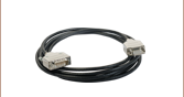
 Zoom
Zoom
The PAA632 Extension Cable provides an additional 2.5 m (8.20 ft) of cable length for the 15-pin D-type connectors used throughout our motorized actuator selection. The male end connects to the controller, while the female end connects to the motor.