 Products Home
Birefringence Imaging System

- Measurements of Retardance and Azimuth
(Fast Axis Orientation) in Flat Samples - Measure Ø20 mm Field of View in <15 s
- Includes Three Sample Holders for
Ø0.5", Ø1", and 2" x 2" Optics
LCC7201
With Included Laptop
Screenshot of the 2D Measurement Display Mode Using the LCC7201's Software


Please Wait
| Specifications | |
|---|---|
| Light Source Wavelengtha | 633 nm |
| Retardance Measurement Range | Standard Retardance Range: 0 to 316 nm Low Retardance Range: 0 to 100 nm |
| Azimuth Measurement Range | ±90° |
| Retardance Measurement Accuracy | Standard Retardance Range: <±10 nm Low Retardance Range: <±1 nm |
| Azimuth Measurement Accuracy | Standard Retardance Range: <±3° Low Retardance Range: <±1° |
| Measurement Rateb | <15 s |
| Field of View | Ø20 mm |
| Spatial Resolution | 9.77 μm |
| Interfaces | USB 2.0 and Gigabit Ethernet |
| Camera Resolution | 2048 x 2048 Pixels |
| Dimensions | 500.0 mm (D) x 360.0 mm (W) x 672.0 mm (H) |
| Weight | 26 kg (57.3 lbs) |
| Operating Temperature | 0 to 40 °C |
| Storage Temperature | -15 to 65 °C |
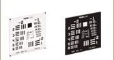
| Included Accessories | Laptop PC, Sample Holders, Birefringent Resolution Target (Item # R2L2S1B) |

Features
- Built-In 633 nm Light Source
- Measures Sample Retardance up to a Half-Wave (316 nm) and Azimuths up to ±90°
- Ø20 mm Field of View
- Complete Imaging System Includes Software and Laptop
- Compatible with MLS203-1 XY Scanning Stage
- Custom Operating Wavelengths by Contacting Tech Support
Thorlabs’ LCC7201 Birefringence Imaging System is designed for use in academic research, medical diagnostics, industrial manufacturing, and product quality assurance; for sample results please see the Applications tab. It measures the retardance and azimuths of flat, planar samples, such as crystals and liquid crystal devices, and is particularly well-suited for characterizing stress-induced birefringence. Since it is based on a liquid crystal device, there is no internal mechanical movement, leading to very stable, vibration-free operation.
The LCC7201 is designed to operate at a wavelength of 633 nm, and provides a Ø20 mm field of view. This system measures retardance up to a half-wave (316 nm) and azimuths up to ±90°. The operation wavelength can be customized to a wavelength from 405 nm to 810 nm. To customize this operational wavelength, please contact Tech Support.
For sample viewing, the LCC7201 includes Thorlabs' MLS203P2 sample holder. It also includes three sample holder inserts that are sized to hold Ø0.5”, Ø1”, and 2” x 2” optics. The MLS203P2 provides manual adjustment in the X direction, which is useful for samples larger than the Ø20 mm field of view. Additionally, larger samples can be scanned by upgrading the system with Thorlabs' MLS203-1 XY Scanning Stage, which provides manual and motorized adjustment in both the X and Y directions. The specifications of the LCC7201 are outlined in the table to the right.
Included with purchase is a laptop with Windows® operating system and the software pre-installed. To view additional information about this system's software features and sample measurement results, please refer to the Software tab above.
Software
Version 1.3.0
Click the button below to visit the LCC7201 Birefringence Imaging System software page.
The LCC7201 system includes a Windows®-based software package that contains everything needed for system control and data acquisition. Please click the Software button to the right to download the latest software for this system.
Features
- Standard and Low Noise Modes for Retardance Measurements
- Selectable Region of Interest (ROI)
- Customizable Measurement Rate
- Adjustable Dynamic Camera Settings (Gain, Exposure Time, Black Levels)
- Overexposure Detection
- Auto Adjustment of Light Source Level
- 1D, 2D, and 3D Measurement Result Displays
- Data Output in Binary and CSV Formats
The LCC7201 software includes two modes, Standard Mode and Low-Noise Mode, to measure a sample's retardance. Standard Mode provides a higher measurement rate with a lower signal-to-noise ratio, while Low Noise Mode provides a lower measurement rate with a higher signal-to-noise ratio. An exposure time of 30 ms is set as the default, which allows a measurement to be finished within 15 seconds in Standard Mode and 3 minutes in Low Noise Mode.
These two modes provide two ranges of measurement accuracy, Standard Retardance Range and Low Retardance Range. Standard Retardance provides a measurement accuracy of <±10 nm for retardances in the 0 to 316 nm range, and <±3° for azimuths over the entire measurement range. Low Retardance Range will improve the measurement accuracy of <±1 nm for retardances in the 0 to 100 nm range, and
<±1° for azimuths over the entire measurement range. The mimimum exposure time is 1 ms, and the maximum exposure time is 10000 ms.
Below are screenshots from the included user interface, showing the different measurement display modes available. The 1D, 2D, and 3D views are all of an m=1, zero-order vortex half-wave plate.

Click to Enlarge
1D View

Click to Enlarge
Camera Preview Showing Included Test Target

Click to Enlarge
3D View

Click to Enlarge
2D View
Application Image Gallery
Inspection of Thorlabs' Quartz Quarter-Wave Plate After LIDT Test

Click to Enlarge
Wave Plate Retardance in 3D View

Click to Enlarge
Wave Plate Retardance in 2D View
Inspection of Thorlabs' Patterned Liquid Crystal Polymer Retarders with Fast-Axis Azimuth Distribution

Click to Enlarge
Thorlabs' m = 1 LCP Vortex Retarder Azimuth and Retardance in 2D View

Click to Enlarge
Thorlabs' m = 2 Vortex Retarder Azimuth and Retardance in 2D View
Inspection of Stress- and Strain-Induced Birefringence in Optical Fiber

Click to Enlarge
Optical Fiber in Preview

Click to Enlarge
Optical Fiber Retardance in 2D View
Analysis of Stress- and Strain-Induced Birefringence for Materials Research and Product Development

Click to Enlarge
Plastic Ruler in Preview

Click to Enlarge
Plastic Ruler Retardance in 2D View
Visualize Cell Birefringence for Cell Behavior Analysis or Cell Screening

Click to Enlarge
Xylophyta Dicotyledon T.S. in Preview

Click to Enlarge
Xylophyta Dicotyledon T.S. Stem in 2D View


Click to Enlarge
China Demo Room
Try Our Microscopes In Person or Virtually
Thorlabs' sales engineers and field service staff are based out of eight offices across four continents. We look forward to helping you determine the best imaging system to meet your specific experimental needs. Our customers are attempting to solve biology's most important problems; these endeavors require matching systems that drive industry standards for ease of use, reliability, and raw capability.
Thorlabs' worldwide network allows us to operate demo rooms in a number of locations where you can see our systems in action. We welcome the opportunity to work with you in person or virtually. A demo can be scheduled at any of our showrooms or virtually by contacting ImagingSales@thorlabs.com.
Customer Support Sites
(Click Each Location for More Details)
Newton, New Jersey, USA

Thorlabs HQ
56 Sparta Avenue
Newton, NJ 07860
Customer Support
- Phone: (973) 300-3000
- E-mail: techsupport@thorlabs.com
Ely, United Kingdom

Thorlabs Ltd.
1 Saint Thomas Place, Ely
Ely CB7 4EX
Customer Support
- Phone: +44 (0)1353-654440
- E-mail: techsupport.uk@thorlabs.com
Bergkirchen, Germany

Thorlabs GmbH
Münchner Weg 1
85232 Bergkirchen
Customer Support
- Phone: +49 (0) 8131-5956-0
- E-mail: europe@thorlabs.com
Maisons-Laffitte, France

Thorlabs SAS
109, rue des Cotes
Maisons-Laffitte 78600
Customer Support
- Phone: +33 (0)970 440 844
- E-mail: techsupport.fr@thorlabs.com
São Carlos, SP, Brazil

Thorlabs Vendas de Fotônicos Ltda.
Rua Rosalino Bellini, 175
Jardim Santa Paula
São Carlos, SP, 13564-050
Customer Support
- Phone: +55-16-3413 7062
- E-mail: brasil@thorlabs.com
Demo Rooms and Customer Support Sites
(Click Each Location for More Details)
Sterling, Virginia, USA

Thorlabs Imaging Systems HQ
108 Powers Court
Sterling, VA 20166
Customer Support
- Phone: (703) 651-1700
- E-mail: ImagingTechSupport@thorlabs.com
Demo Rooms
- Bergamo® II Series Multiphoton Microscopes
- Veneto™ Inverted Microscopes
- Single- and Multi-Channel Cerna®-Based Confocal Microscopes
- Confocal Upgrade for Existing Systems
- Cerna Hyperspectral Imaging System
- Multiphoton Mesoscope
- Birefringence Imaging System
- OCT Systems: Vega™, Telesto™, and Ganymede™
Lübeck, Germany

Thorlabs GmbH
Maria-Goeppert-Straße 9
23562 Lübeck
Customer Support
- Phone: +49 (0) 8131-5956-40840
- Email: oct@thorlabs.com
Demo Rooms
- Ganymede™ Series SD-OCT Systems
- Telesto™ Series SD-OCT Systems
- Telesto™ Series PS-OCT Systems
- Atria™ Series SS-OCT Systems
- Vega™ Series SS-OCT Systems
Nerima-ku, Tokyo, Japan

Thorlabs Japan, Inc.
3-6-3 Kitamachi
Nerima-ku, Tokyo 179-0081
Customer Support
- Phone: +81-3-6915-7701
- Email: sales@thorlabs.jp
Demo Rooms
- Four-Channel Cerna®-Based Confocal Systems
- Cerna® Modular Brightfield Microscopes
- OCT Systems: Ganymede™
Shanghai, China

Thorlabs China
Room A101, No. 100, Lane 2891, South Qilianshan Road
Shanghai 200331
Customer Support
- Phone: +86 (0)21-60561122
- Email: techsupport-cn@thorlabs.com
Demo Rooms
- Bergamo® II Series Multiphoton Microscopes
- Single-Channel Cerna®-Based Confocal Microscopes
- Galvo-Galvo or Galvo-Resonant Confocal Upgrade for Existing Systems
- OCT Systems: Telesto™ and Ganymede™
| Posted Comments: | |
| No Comments Posted |