 Products Home
Rigid Stands

- Height-Adjustable Stands with 360° Rotation
- Mount Samples & Experimental Apparatuses
- Compatible with Upright or Inverted Microscopes
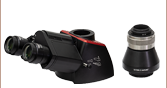
MP200
Rigid Stand with Platform
Application Idea
MZS500-E Z-Axis Piezo Stage Mounted Using an MP100-MLSH Stand with Insert
MP200-RCH2 Adjustable Stand Shown Holding a Microscope Slide Between an Objective and Condenser


Please Wait

| Item # Prefix |
Platform/Holder Heighta | |
|---|---|---|
| Min | Max | |
| MP100 | 5.83" (148.1 mm) | 8.21" (208.5 mm) |
| MP150 | 7.80" (198.1 mm) | 12.18" (309.3 mm) |
| MP200 | 9.77" (248.1 mm) | 16.14" (410.1 mm) |
| MP250 | 11.74" (298.1 mm) | 20.11" (510.9 mm) |
The above animation shows how the rigid stands can be adjusted.
Features
- Rigid Stands Hold Samples or Experimental Apparatuses Underneath and Around the Objective
- Designed for Slides, Petri Dishes, Recording Chambers, Micromanipulators, Well Plates, and DIY Inserts
- Suitable for Upright and Inverted Microscopes
- Base Plate Features Four Slots for 1/4"-20 (M6) Cap Screws for Table Mounting
- Four Versions Support Heights from 5.83" to 20.11" (148.1 mm to 510.9 mm)
- Red Post Holders Compatible with 66 mm Rail Accessories and Mounts
- Translation Stages Available Separately
Thorlabs' Adjustable Rigid Stands provide additional flexibility and adaptability to any microscopy application. Each stand has a slim profile that consumes a minimal amount of space in and around the optical path. This leaves ample approach room for any objectives, micromanipulators, a condenser, and other equipment, making it easy to work around the setup. Additionally, with versions designed for slides, petri dishes, recording chambers, micromanipulators, well plates, and general electrophysiology applications, our rigid stands can be used in virtually any setup.
Each rigid stand provides 360° rotational adjustment allowing a mounted component to be easily positioned within the imaging system. As shown by the table above, the stands are offered in four versions that together support heights from 5.83" to 20.11" (148.1 mm to 510.9 mm), measured from the bottom of the base to the top of the platform.
As illustrated by the animation to the right, a quick-release clamp locks and unlocks the included post. The included post collar with an alignment pin can be used to maintain the post's height during its rotation. The alignment pin acts as a hard mechanical stop that lets you quickly return to a previously set angle. To raise or lower the post within its given vertical range, it is necessary to loosen the collar, which is locked onto the post using a cap screw that accepts a 4 mm (5/32") balldriver. Each post is housed inside a red post holder, which is compatible with 66 mm rail accessories and optomechanical mounts.
We also offer two types of manual translation stages that provide 25 mm of translation in one or two horizontal axes and are compatible with our rigid stands via the MPA1(/M) adapter plate. The manual stages with quick connect feature dovetails that allow users to construct their own multi-axis stage, while the self-contained manual stages offer a more compact footprint. Thorlabs also manufactures motorized translation stages for these rigid stands that enable 1" of horizontal travel in one or two axes.
For sample holders that attach directly to the DIY Cerna® microscope body, please see our manual and motorized XY stages.


| Selection Guide for Rigid Stand Translation Stages | ||
|---|---|---|
 Manual Stages with Quick Connect |
 Self-Contained Manual Stages |
 Motorized Stages |
Building a Cerna® Microscope
The Cerna microscopy platform's large working volume and system of dovetails make it straightforward to connect and position the components of the microscope. This flexibility enables simple and stable set up of a preconfigured microscope, and provides easy paths for later upgrades and modification. See below for a couple examples of the assembly of preconfigured and DIY Cerna microscopes.
Preconfigured Microscope Kit Design and Assembly
Walkthrough of Cerna® Microscope Kit 4
This Cerna microscope configuration is equipped with both epi- and trans-illumination modules. All Cerna preconfigured microscope kits enable individual components to be removed or substituted for complete customization.
The D1N and D2N circular dovetails align the sample viewing and epi-illumination apparatus along the optical path. The microscope body's 95 mm linear dovetail is used to secure the objective mounts and condenser mounts, as well as the transmitted light illumination module. The dovetail allows components to slide along the vertical rail prior to lockdown.
DIY Cerna Design and Assembly
Walkthrough of a DIY Microscope Configuration
This DIY microscope uses a CSA3000(/M) Breadboard Top, a CSA2001 Dovetail Adapter, our CSA1001 and CSA1002 Fixed Arms, and other body attachments and extensions. These components provide interfaces to our lens tube and cage construction systems, allowing the rig to incorporate two independent trans-illumination modules, a home-built epi-illumination path, and a custom sample viewing optical path.
DIY Microscope Configuration Assembly
The simplicity of Thorlabs optomechanical interfaces allows a custom DIY microscope to be quickly assembled and reconfigured for custom imaging applications.
The Cerna® Mind Map is a visual tool that contains the complete selection of DIY Cerna components and several closely related accessories. Created as a supplement to our website, we have designed it to be printed on a single 11" x 17" sheet.
Click here or on the image below to download a printable PDF. The components shown on this webpage are in Step 8 of the mind map.

| Posted Comments: | |
jtdo
(posted 2019-03-08 17:54:35.08) Is the red part of the rigid stand the same as a 66mm optical rail? And if so, can I mount the rail carriage (XT66P2) to it? Thanks! mmcclure
(posted 2019-03-11 01:58:11.0) Hello, thank you for contacting us. The rigid stands' red post holder is compatible with our 66 mm optical rail components and accessories, including the XT66P2 rail carriage. We will update the webpage presentation to make this compatibility more apparent. timothee.labouret
(posted 2017-06-26 17:01:08.433) Hi,
I have a question regarding the MP200. Is the post removable from the post holder in order to extend it with another 1.5" post ? Also, is the platform removable from the post to yield a normal 1.5" post ? Thank you for your support. Regards tfrisch
(posted 2017-06-27 04:37:05.0) Hello, thank you for contacting Thorlabs. The post is removable and a different 1.5" diameter post can be used. |
Click on the different parts of the microscope to explore their functions.

Elements of a Microscope
This overview was developed to provide a general understanding of a Cerna® microscope. Click on the different portions of the microscope graphic to the right or use the links below to learn how a Cerna microscope visualizes a sample.
Terminology
Arm: Holds components in the optical path of the microscope.
Bayonet Mount: A form of mechanical attachment with tabs on the male end that fit into L-shaped slots on the female end.
Bellows: A tube with accordion-shaped rubber sides for a flexible, light-tight extension between the microscope body and the objective.
Breadboard: A flat structure with regularly spaced tapped holes for DIY construction.
Dovetail: A form of mechanical attachment for many microscopy components. A linear dovetail allows flexible positioning along one dimension before being locked down, while a circular dovetail secures the component in one position. See the Microscope Dovetails tab or here for details.
Epi-Illumination: Illumination on the same side of the sample as the viewing apparatus. Epi-fluorescence, reflected light, and confocal microscopy are some examples of imaging modalities that utilize epi-illumination.
Filter Cube: A cube that holds filters and other optical elements at the correct orientations for microscopy. For example, filter cubes are essential for fluorescence microscopy and reflected light microscopy.
Köhler Illumination: A method of illumination that utilizes various optical elements to defocus and flatten the intensity of light across the field of view in the sample plane. A condenser and light collimator are necessary for this technique.
Nosepiece: A type of arm used to hold the microscope objective in the optical path of the microscope.
Optical Path: The path light follows through the microscope.
Rail Height: The height of the support rail of the microscope body.
Throat Depth: The distance from the vertical portion of the optical path to the edge of the support rail of the microscope body. The size of the throat depth, along with the working height, determine the working space available for microscopy.
Trans-Illumination: Illumination on the opposite side of the sample as the viewing apparatus. Brightfield, differential interference contrast (DIC), Dodt gradient contrast, and darkfield microscopy are some examples of imaging modalities that utilize trans-illumination.
Working Height: The height of the support rail of the microscope body plus the height of the base. The size of the working height, along with the throat depth, determine the working space available for microscopy.
 Click to Enlarge
Cerna Microscope Body

Click to Enlarge
Body Details
Microscope Body
The microscope body provides the foundation of any Cerna microscope. The support rail utilizes 95 mm rails machined to a high angular tolerance to ensure an aligned optical path and perpendicularity with the optical table. The support rail height chosen (350 - 600 mm) determines the vertical range available for experiments and microscopy components. The 7.74" throat depth, or distance from the optical path to the support rail, provides a large working space for experiments. Components attach to the body by way of either a linear dovetail on the support rail, or a circular dovetail on the epi-illumination arm (on certain models). Please see the Microscope Dovetails tab or here for further details.
 Click to Enlarge
Illumination with a Cerna microscope can come from above (yellow) or below (orange). Illumination sources (green) attach to either.
Illumination
Using the Cerna microscope body, a sample can be illuminated in two directions: from above (epi-illumination, see yellow components to the right) or from below (trans-illumination, see orange components to the right).
Epi-illumination illuminates on the same side of the sample as the viewing apparatus; therefore, the light from the illumination source (green) and the light from the sample plane share a portion of the optical path. It is used in fluorescence, confocal, and reflected light microscopy. Epi-illumination modules, which direct and condition light along the optical path, are attached to the epi-illumination arm of the microscope body via a circular D1N dovetail (see the Microscope Dovetails tab or here for details). Multiple epi-illumination modules are available, as well as breadboard tops, which have regularly spaced tapped holes for custom designs.
Trans-illumination illuminates from the opposite side of the sample as the viewing apparatus. Example imaging modalities include brightfield, differential interference contrast (DIC), Dodt gradient contrast, oblique, and darkfield microscopy. Trans-illumination modules, which condition light (on certain models) and direct it along the optical path, are attached to the support rail of the microscope body via a linear dovetail (see Microscope Dovetails tab or here). Please note that certain imaging modalities will require additional optics to alter the properties of the beam; these optics may be easily incorporated in the optical path via lens tubes and cage systems. In addition, Thorlabs offers condensers, which reshape input collimated light to help create optimal Köhler illumination. These attach to a mounting arm, which holds the condenser at the throat depth, or the distance from the optical path to the support rail. The arm attaches to a focusing module, used for aligning the condenser with respect to the sample and trans-illumination module.
 |
 |
 |
 |
 |
 |
 |
 |
| Epi-Illumination Modules | Breadboards & Body Attachments |
Brightfield | DIC | Dodt | Condensers | Condenser Mounting | Light Sources |
 Click to Enlarge
Light from the sample plane is collected through an objective (blue) and viewed using trinocs or other optical ports (pink).
Sample Viewing/Recording
Once illuminated, examining a sample with a microscope requires both focusing on the sample plane (see blue components to the right) and visualizing the resulting image (see pink components).
A microscope objective collects and magnifies light from the sample plane for imaging. On the Cerna microscope, the objective is threaded onto a nosepiece, which holds the objective at the throat depth, or the distance from the optical path to the support rail of the microscope body. This nosepiece is secured to a motorized focusing module, used for focusing the objective as well as for moving it out of the way for sample handling. To ensure a light-tight path from the objective, the microscope body comes with a bellows (not pictured).
Various modules are available for sample viewing and data collection. Trinoculars have three points of vision to view the sample directly as well as with a camera. Double camera ports redirect or split the optical path among two viewing channels. Camera tubes increase or decrease the image magnification. For data collection, Thorlabs offers both cameras and photomultiplier tubes (PMTs), the latter being necessary to detect fluorescence signals for confocal microscopy. Breadboard tops provide functionality for custom-designed data collection setups. Modules are attached to the microscope body via a circular dovetail (see the Microscope Dovetails tab or here for details).


 Click to Enlarge
The rigid stand (purple) pictured is one of various sample mounting options available.
Sample/Experiment Mounting
Various sample and equipment mounting options are available to take advantage of the large working space of this microscope system. Large samples and ancillary equipment can be mounted via mounting platforms, which fit around the microscope body and utilize a breadboard design with regularly spaced tapped through holes. Small samples can be mounted on rigid stands (for example, see the purple component to the right), which have holders for different methods of sample preparation and data collection, such as slides, well plates, and petri dishes. For more traditional sample mounting, slides can also be mounted directly onto the microscope body via a manual XY stage. The rigid stands can translate by way of motorized stages (sold separately), while the mounting platforms contain built-in mechanics for motorized or manual translation. Rigid stands can also be mounted on top of the mounting platforms for independent and synchronized movement of multiple instruments, if you are interested in performing experiments simultaneously during microscopy.
 |
 |
 |
 |
 |
| Translating Platforms | Rigid Stands | Translation Stages for Rigid Stands | Motorized XY Stages | Manual XY Stage |
For sample viewing, Thorlabs offers trinoculars, double camera ports, and camera tubes. Light from the sample plane can be collected via cameras, photomultiplier tubes (PMTs), or custom setups using breadboard tops. Click here for additional information about viewing samples with a Cerna microscope.
| Product Families & Web Presentations | |||
 |
|
 |
 |
| Sample Viewing | Breadboards & Body Attachments |
Cameras | PMTs |
Microscope objectives are held in the optical path of the microscope via a nosepiece. Click here for additional information about viewing a sample with a Cerna microscope.
| Product Families & Web Presentations | ||||
 |
 |
 |
 |
 |
| Objectives | Objective Thread Adapters | Parfocal Length Extender | Piezo Objective Scanner | Objective Mounting |
Large and small experiment mounting options are available to take advantage of the large working space of this microscope. Click here for additional information about mounting a sample for microscopy.
| Product Families & Web Presentations | ||||
|
|
|
|
 |
| Translating Platforms | Rigid Stands | Translation Stages for Rigid Stands | Motorized XY Stages | Manual XY Stage |
Thorlabs offers various light sources for epi- and trans-illumination. Please see the full web presentation of each to determine its functionality within the Cerna microscopy platform.
| Product Families & Web Presentations | ||||
 |
 |
 |
 |
|
| Trans-Illumination Kits | Solis™ High-Power LEDs | Mounted LEDs | X-Cite® Lamps | Other Light Sources |
Epi-illumination illuminates the sample on the same side as the viewing apparatus. Example imaging modalities include fluorescence, confocal, and reflected light microscopy. Click here for additional information on epi-illumination with Cerna.
| Product Families & Web Presentations | ||
|
|
|
| Epi-Illumination | Body Attachments | Light Sources |
Trans-illumination illuminates from the opposite side of the sample as the viewing apparatus. Example imaging modalities include brightfield, differential interference contrast (DIC), Dodt gradient contrast, oblique, and darkfield microscopy. Click here for additional information on trans-illumination with Cerna.
| Product Families & Web Presentations | ||||||
|
|
|
|
 |
|
|
| Brightfield | DIC | Dodt | Condensers | Condenser Mounting | Illumination Kits | Other Light Sources |
The microscope body provides the foundation of any Cerna microscope. The 7.74" throat depth provides a large working space for experiments. Click here for additional information about the Cerna microscope body.
| Product Families & Web Presentations | |
 |
 |
| Microscope Bodies | Microscope Translator |

 Zoom
Zoom

- Designed for Multiple Slides, Petri Dishes, Our MZS500-E Z-Axis Piezo Stage, Well Plates, and User-Designed Inserts
- Quick-Release Clamp Enables Tool-Free Positioning
- Collar Provides Stops at User-Specified Height and Angle
- Horizontal, Vertical, and Rotational Adjustments Provide Flexible Positioning
- Translation Stages for Rigid Stands Available
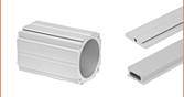
These rigid stands contain a rectangular slot that is compatible with the 6.70" x 5.13" inserts shown below (which are sold separately). These inserts can be used to mount samples or experimental equipment in or near the optical path of the Cerna microscope, enabling a variety of experimental configurations beyond those achievable with our more basic sample holders. Eight M6 x 1.0 tapped holes on top of the platform can be used to mount additional experimental equipment
To allow you to fine tune the location of the insert, the bottom of the platform has been equipped with a slidable dovetail. This dovetail, which is also used in Thorlabs' 66 mm optical rails, is held in place by two screws that accept a 2.5 mm balldriver. Loosening these screws lets the insert translate horizontally over a 2.56" (65.0 mm) range. This long adjustment range also lets the red post holder be positioned over a range of locations on the tabletop.
The base can be secured to a tabletop via four counterbored slots that accept 1/4"-20 (M6) cap screws. The base is also compatible with the MPA1(/M) adapter plate that allows a rigid stand to be mounted on a translation stage.
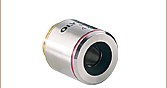
Compatible Inserts
The inserts in the table below are designed for our Rigid Stand Insert Holders and the MLS203-1 and MLS203-2 Fast XY Scanning Stages.
| Slide, Petri Dish, Calibration Target, and Well Plate Holders | |||
|---|---|---|---|
|
|
|
|
|


| Z-Axis Piezo Stage | Holders for User-Designed Inserts | ||
|---|---|---|---|
|
|
|
|
|


 Zoom
Zoom

Click to Enlarge
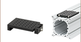
Drawing of Rigid Stand Post Holders
- Empty Post Holder with Included Post Collar
- Available in Four Heights
- Accepts Ø1.5" Stainless Steel Posts
- Compatible with 66 mm Rail Accessories and Mounts
- Translation Stages for Rigid Stands Available
These are the same red post holders included with the rigid stands sold above. They are available in heights of 100 mm, 150 mm, 200 mm, and 250 mm, as defined by the drawing to the right. Each holder includes the same collar and alignment pin that is provided with each rigid stand.
Additional post holders can be used to save reference positions on the tabletop or safely store sample holders that are not in use. Alternatively, by purchasing a taller post holder than one you already have, the vertical range of your sample holder can be effectively increased. Note, however, that rigid stands with item # prefixes MP100, MP150, MP200, and MP250 come with 100 mm, 150 mm, 200 mm, and 250 mm tall posts, respectively. Therefore, a shorter post holder cannot be used to reduce the platform height of a taller rigid stand.
The base can be secured to a tabletop via four counterbored slots that accept 1/4"-20 (M6) cap screws. The base is also compatible with the MPA1(/M) adapter plate that allows a rigid stand to be mounted on a translation stage. These post holders also accept Ø1.5" stainless steel posts for DIY mounting options.