 Products Home / Motorized Stages / Linear Long Travel (>100 mm) Motorized Stages / 300 mm Linear Translation Stage and Controller, Direct-Drive Servo Motor
300 mm Linear Translation Stage and Controller, Direct-Drive Servo Motor

- 300 mm Travel at Speeds up to 400 mm/s
- Brushless DC Servo Motors
- Direct Drive - No Leadscrew
DDS300-E
Kit Includes Stage
and Controller
DDSA04
Platform Height Adapter
MJC001
2-Axis Joystick


Please Wait
| Key DDS300-E Specificationsa | |
|---|---|
| Travel Range | 300 mm (11.81") |
| Velocity (Max) | 400 mm/s |
| Acceleration (Max) | 10,000 mm/s2 |
| Bidirectional Repeatabilityb | ±0.25 µm |
| Backlashc | N/A |
| Horizontal Load Capacity (Max)d | 10.0 kg (22.0 lbs) |
| Min. Achievable Incremental Movemente | 100 nm |
| Absolute On-Axis Accuracy | ±7.5 µm |
| Cable Length | 2.5 m (8.2') |
| Included Controllera | BBD201 |
| Stage Dimensions (L x W x H) | 500 mm x 130 mm x 50 mm (19.69" x 5.12" x 1.97") |
| Motorized Linear Translation Stages | |
|---|---|
| 100 mm | Stepper |
| 150 mm | Stepper |
| Stepper with Integrated Controller | |
| 220 mm | DC Servo |
| 300 mm | Stepper with Integrated Controller |
| DC Servo with Benchtop Controller | |
| 600 mm | DC Servo with Benchtop Controller |
| Optical Delay Line Kits | |
| Other Translation Stages | |
Features
- Complete Stage and Controller Package
- 300 mm (11.81") Travel
- High Speeds up to 400 mm/s
- Low Profile: 50 mm (1.97")
- Integrated, Brushless DC Linear Servo Motor Actuators
- High-Quality, Precision-Engineered Linear Bearings
- Accessories Available:
- Height Adapter for 62.5 mm Platform Height (DDSA04)
- 2-Axis Joystick for Precise Manual Control (MJC001)
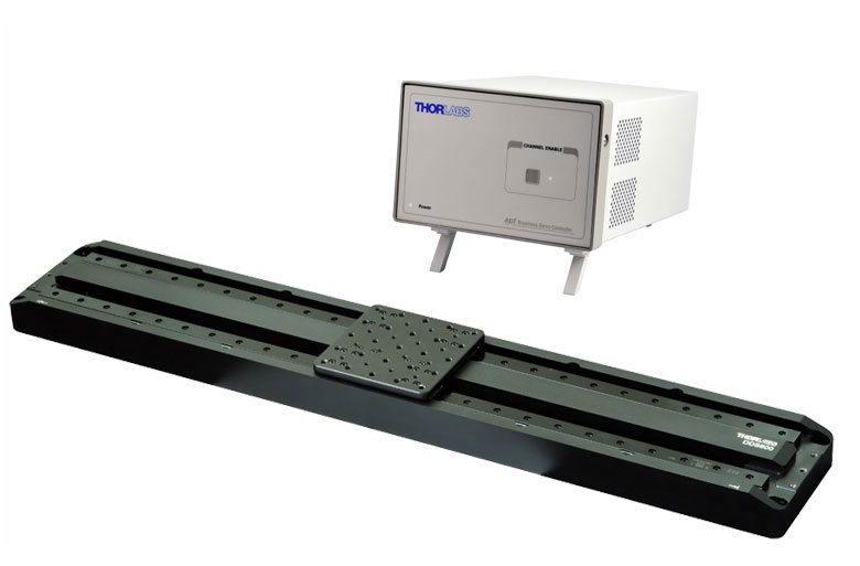
Thorlabs' DDS300-E Low-Profile, Direct-Drive Translation Stage provides 300 mm of travel with a minimum incremental movement of 100 nm and a maximum speed of 400 mm/s. This stage is ideal for applications that require high speeds and high positioning accuracy, including automated alignment, surface inspection, mapping, and probing.
An innovative, low-profile design with integrated, brushless linear motors eliminates the external housings that create mechanical clash points and impede access to the moving platform. The direct-drive technology removes the need for a leadscrew, eliminating backlash. Internal flexible ducting ensures cables cannot become trapped as the mechanism moves. Twin, precision-grooved linear bearings provide superior rigidity and linearity with excellent on-axis accuracy (±7.5 µm). This backlash-free operation coupled with high-resolution, closed-loop optical feedback ensures a bidirectional repeatability of ±0.25 μm.
Controller
A BBD201 single-axis Brushless DC Motor Controller is included with the stage. This controller provides a user-configurable, S-curve acceleration/deceleration profile that enables fast, smooth positioning without vibration or shock. It is ideal for motion control applications demanding operation at high speeds (hundreds of mm/s) and high encoder resolution (50 nm). The design incorporates the latest digital and analog techniques as well as high-bandwidth, high-power servo control circuitry. The controllers ship with our APT software for easy integration into an existing system. For multi-axis applications the stage can also be driven by our BBD202 and BBD203 2-Axis and 3-Axis Controllers.
Joystick Option
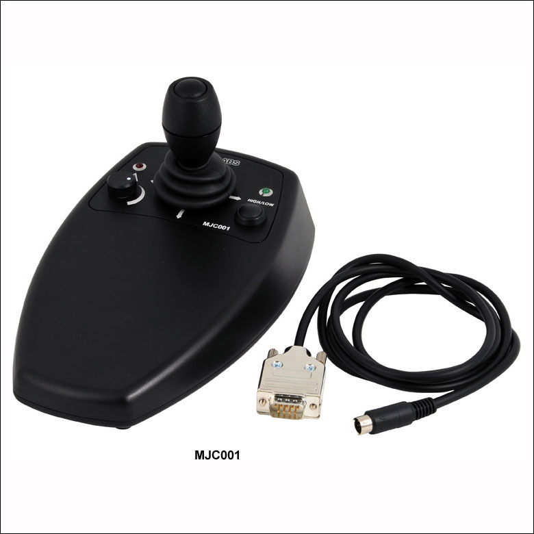
An optional 2-axis joystick console (MJC001) is also available for remote positioning applications. See the presentation below for more details. Please note that in order to control two stages simultaneously, a multi-axis BBD202 or BBD203 controller is required.
Optical Height Adapter Plate
The DDSA04 riser plate attaches directly to the DDS300-E stage and raises the deck height of the stage to 62.5 mm, which matches that of our NanoMax, MicroBlock, and RollerBlock stages.
Usage Notes
These stages are not suitable for operation in a vertical (Z-axis) orientation. In addition, when no power is applied, the platform of the stage has very little inertia and is virtually free running. This may make the stage unsuitable for applications where the stage's platform needs to remain in a set position when power is off.
| DDS300 Linear Motor Stage | |
|---|---|
| Travel Range | 300 mm (11.81") |
| Velocity (Max) | 400 mm/s |
| Acceleration (Max) | 10000 mm/s2 |
| Bidirectional Repeatabilitya | ±0.25 µm |
| Backlashb | N/A |
| Encoder Resolution | 50 nm |
| Min. Achievable Incremental Movementc | 100 nm |
| Horizontal Load Capacity (Max)d | 10.0 kg (22.0 lb) |
| Absolute On-Axis Accuracy | ±7.5 µm |
| Straightness/Flatness | ±4.0 µm |
| Pitch | ±100 µrad |
| Yaw | ±150 µrad |
| Continuous Motor Force | 10.0 N |
| Peak Motor Force (2 sec) | 20.0 N |
| Bearing Type | High Rigidity, Recirculating, Precision Linear Bearings |
| Limit Switches | Magnetic Sensor at Each End of Stage |
| Operating Temperature Rangee | 5 to 40 °C (41 to 104 °F) |
| Motor Type | Brushless DC Linear Motor |
| Cable Length | 2.5 m (8.2') |
| Dimensions | 500 mm x 130 mm x 50 mm (19.69" x 5.12" x 1.97") |
| Weight (Excluding Cables) | 5.9 kg (12.98 lbs) |
| BBD201 Controller | |
|---|---|
| Drive Connector | 8-Pin DIN, Round, Female |
| Feedback Connector | 15-Pin D-Type |
| Continuous Drive Output | 2.5 A |
| PWM Frequency | 40 kHz |
| Operating Modes | Position and Velocity |
| Control Algorithm | 16-Bit Digital PID Servo Loop with Velocity and Acceleration Feedforward |
| Velocity Profile | Trapezoidal/S-Curve |
| Position Count | 32 Bit |
| Position Feedback | Incremental Encoder |
| Encoder Bandwidth | 2.5 MHz 10 M Counts/s |
| Encoder Supply | 5 V |
| AUX Control Connector | 15-Pin D-Type |
| Power Supply Input | Power: 250 VA Voltage: 100 to 240 VAC Frequency: 47 to 63 Hz Fuse: 3.15 A |
| Dimensions | 174 mm x 245 mm x 126 mm (6.85" x 9.65" x 4.96") |
| Weight | 3.46 kg (7.60 lbs) |
The flying leads are terminated in a male 15-pin D-Type and male 8-pin round DIN connector. Pin details are given below.
Feedback Connector

Motor Drive Connector

| Pin | Description | Pin | Description |
|---|---|---|---|
| 1 | Not Used | 9 | Ground |
| 2 | Ground | 10 | Limit Switch + |
| 3 | Not Used | 11 | Limit Switch - |
| 4 | Enconder Index - | 12 | Encoder Index + |
| 5 | Encoder Phase B - | 13 | Encoder Phase B + |
| 6 | Encoder Phase A - | 14 | Encoder Phase A + |
| 7a | 5 V | 15 | Not Used |
| 8a | 5 V |
| Pin | Description |
|---|---|
| 1 | Motor Phase V |
| 2 | Ground |
| 3 | Thermistor (Not Used) |
| 4 | Motor Phase U |
| 5 | Stage ID |
| 6 | Ground |
| 7 | Motor Phase W |
| 8 | Enable |
Thorlabs offers two platforms to drive our wide range of motion controllers: our Kinesis® software package or the legacy APT™ (Advanced Positioning Technology) software package. Either package can be used to control devices in the Kinesis family, which covers a wide range of motion controllers ranging from small, low-powered, single-channel drivers (such as the K-Cubes™ and T-Cubes™) to high-power, multi-channel, modular 19" rack nanopositioning systems (the APT Rack System).
The Kinesis Software features .NET controls which can be used by 3rd party developers working in the latest C#, Visual Basic, LabVIEW™, or any .NET compatible languages to create custom applications. Low-level DLL libraries are included for applications not expected to use the .NET framework. A Central Sequence Manager supports integration and synchronization of all Thorlabs motion control hardware.

Kinesis GUI Screen

APT GUI Screen
Our legacy APT System Software platform offers ActiveX-based controls which can be used by 3rd party developers working on C#, Visual Basic, LabVIEW™, or any Active-X compatible languages to create custom applications and includes a simulator mode to assist in developing custom applications without requiring hardware.
By providing these common software platforms, Thorlabs has ensured that users can easily mix and match any of the Kinesis and APT controllers in a single application, while only having to learn a single set of software tools. In this way, it is perfectly feasible to combine any of the controllers from single-axis to multi-axis systems and control all from a single, PC-based unified software interface.
The software packages allow two methods of usage: graphical user interface (GUI) utilities for direct interaction with and control of the controllers 'out of the box', and a set of programming interfaces that allow custom-integrated positioning and alignment solutions to be easily programmed in the development language of choice.
A range of video tutorials is available to help explain our APT system software. These tutorials provide an overview of the software and the APT Config utility. Additionally, a tutorial video is available to explain how to select simulator mode within the software, which allows the user to experiment with the software without a controller connected. Please select the APT Tutorials tab above to view these videos.
Software
Kinesis Version 1.14.25
The Kinesis Software Package, which includes a GUI for control of Thorlabs' Kinesis and APT™ system controllers.
Also Available:
- Communications Protocol
Software
APT Version 3.21.4
The APT Software Package, which includes a GUI for control of Thorlabs' APT™ and Kinesis system controllers.
Also Available:
- Communications Protocol
These videos illustrate some of the basics of using the APT System Software from both a non-programming and a programming point of view. There are videos that illustrate usage of the supplied APT utilities that allow immediate control of the APT controllers out of the box. There are also a number of videos that explain the basics of programming custom software applications using Visual Basic, LabView and Visual C++. Watch the videos now to see what we mean.
 |
Click here to view the video tutorial | |
To further assist programmers, a guide to programming the APT software in LabView is also available.
 |
Click here to view the LabView guide | |
| Posted Comments: | |
user
(posted 2019-04-12 03:26:47.54) Hello! Does 300 mm of travel mean that if something were mounted on the center of this stage, it could travel up to 300 mm? Or is that the distance from one end of the path to the other? In other words, does the 300 mm of travel take into account the size of the stage that is moving? rmiron
(posted 2019-04-12 06:14:10.0) Response from Radu at Thorlabs: 300 mm is the full travel range of the stage, from one end to the other. More specifically, it is the distance between the two end limit switches. Anything mounted on DDS300(/M) can move by 300 mm. The total length of the stage is 500 mm, as is shown in the CAD drawings posted under "Docs", on the main tab. I hope this answers your question. gert
(posted 2017-06-27 15:43:42.607) Hi,
We want to operate a DDS300-E at a constant velocity in the range of 1 to 10 mm/s. Would it be possible to give us a spec or estimate for the stability of the velocity that can be achieved with this stage?
Thank you,
Gert awebber-date
(posted 2017-07-03 10:36:45.0) Response from Alex at Thorlabs: When trying to run servo motors at these extremely low velocities there will be some fluctuations in the speed of the stage. We evaluated a DDS220's performance at various set speeds using interferometer when carrying a load of 500g and after 5 million cycles of soak testing,typical velocity fluctuations were ±0.5mm at 10mm/s and ±0.3mm at 1mm/s (with a background noise of 0.006mm/s when stationary). sipos
(posted 2015-09-25 18:06:31.23) Dera Sir/Madam,
Can this translator be mounted vertically? In this case what is the maximum torque load? GHow does this effect the Pitch/yaw specs?
Best regards
Áron SIPOS rcapehorn
(posted 2015-09-30 09:40:29.0) Response from Rob at Thorlabs: Unfortunately our brushless stages are not designed to be run vertically. The main problem is that when the stage is powered down there is nothing to hold the moving world in place, so it will drop back to the home position, which could result in damage to the stage.
If you need to use a stage in a vertical configuration then you would need to use something with a lead screw such as the LTS300/M, the main disadvantage with this type of stage is that the maximum velocity will be much slower and also the positional resolution is not as good as with the DDS300/M stage as there is no encoder in the LTS300/M but this it the longest vertical travel stage that Thorlabs can currently offer. |
Motorized Linear Translation Stages
Thorlabs' motorized linear translation stages are offered in a range of maximum travel distances, from a stage with 20 µm of piezo translation to our 600 mm direct drive stage. Many of these stages can be assembled in multi-axis configurations, providing XY or XYZ translation. For fiber coupling applications, please see our multi-axis stages, which offer finer adjustment than our standard motorized translation stages. In addition to motorized linear translation stages, we offer motorized rotation stages, pitch and yaw platforms, and goniometers. We also offer manual translation stages.
Piezo Stages
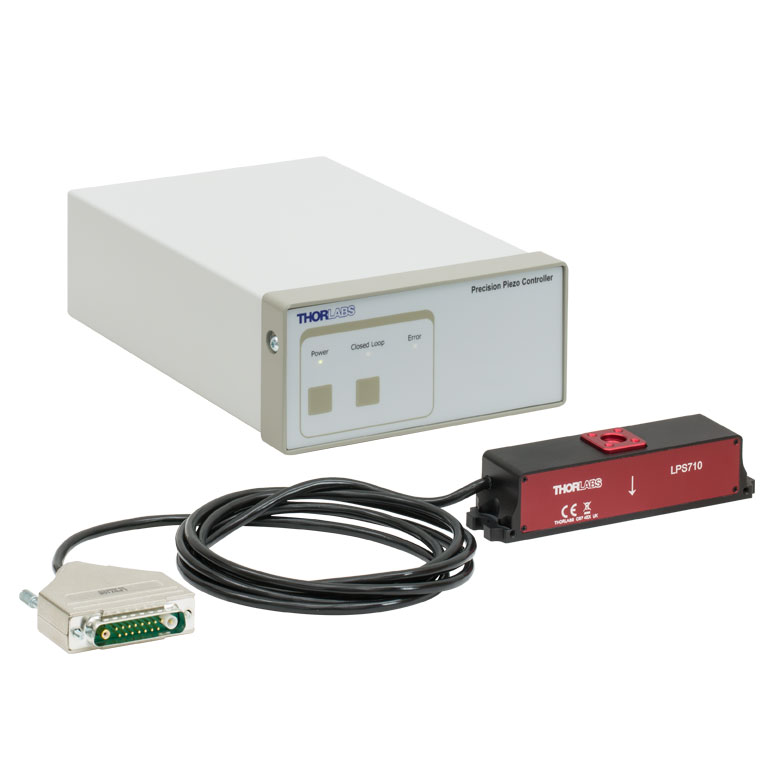
These stages incorporate piezoelectric elements in a variety of drive mechanisms. Our Nanoflex™ translation stages use standard piezo chips along with manual actuators. Our LPS710E z-axis stage features a mechanically amplified piezo design and includes a matched controller. The PD1 stage incorporates a piezo inertia drive that uses "stick-slip" friction properties to obtain an extended travel range. The Elliptec™ stages use resonant piezo motors to push and pull the moving platform through resonant elliptical motion.
| Piezoelectric Stages | ||||||
|---|---|---|---|---|---|---|
| Product Family | Nanoflex™ 20 µm Stage with 5 mm Actuator |
Nanoflex™ 25 µm Stage with 1.5 mm Actuator |
LPS710E 1.1 mm Z-Axis Stage |
PD1 20 mm Stage | Elliptec™ 28 mm Stage | Elliptec™ 60 mm Stage |
| Click Photo to Enlarge |
 |
 |
 |
 |
 |
 |
| Travel | 20 µm + 5 mm Manual | 25 µm + 1.5 mm Manual | 1.1 mm | 20 mm | 28 mm | 60.0 mm |
| Maximum Velocity | - | - | 3 mm/s | 180 mm/s | 90 mm/s | |
| Drive Type | Piezo with Manual Actuator | Amplified Piezo | Piezoelectric Inertia Drive | Resonant Piezoelectric Motor | ||
| Possible Axis Configurations |
X, XY, XYZ | - | X, XY, XYZ | X | ||
| Additional Details | ||||||
Stepper Motor Stages
These translation stages feature removable or integrated stepper motors and long travel ranges up to 300 mm. The MLJ150 stage also offers high load capacity vertical translation. The other stages can be assembled into multi-axis configurations.
| Stepper Motor Stages | |||||||
|---|---|---|---|---|---|---|---|
| Product Family | LNR Series 25 mm Stage |
LNR Series 50 mm Stage |
MLJ150 50 mm Vertical Stage |
NRT Series 100 mm Stage |
NRT Series 150 mm Stage |
LTS Series 150 mm Stage |
LTS Series 300 mm Stage |
| Click Photo to Enlarge |
 |
 |
 |
 |
 |
 |
 |
| Travel | 25 mm | 50 mm | 50 mm | 100 mm | 150 mm | 150 mm | 300 mm |
| Maximum Velocity | 2.0 mm/s | 50 mm/s | 3.0 mm/s | 30 mm/s | 50 mm/s | ||
| Possible Axis Configurations |
X, XY, XYZ | X, XY, XYZ | - | X, XY, XYZ | X, XY, XYZ | ||
| Additional Details | |||||||
DC Servo Motor Stages
Thorlabs offers linear translation stages with removable or integrated DC servo motors. These stages feature low profiles and can be assembled in multi-axis configurations.
| DC Servo Motor Stages | |||||
|---|---|---|---|---|---|
| Product Family | MT Series 12 mm Stages | PT Series 25 mm Stages | MTS Series 25 mm Stage | MTS Series 50 mm Stage | KVS30 30 mm Vertical Stage |
| Click Photo to Enlarge |  |
 |
 |
 |
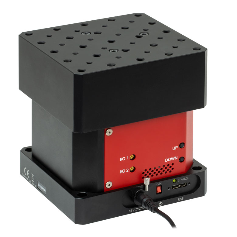 |
| Travel | 12 mm | 25 mm | 25 mm | 50 mm | 30 mm |
| Maximum Velocity | 2.6 mm/s | 2.4 mm/s | 8.0 mm/s | ||
| Possible Axis Configurations | X, XY, XYZ | X, XY, XYZ | - | ||
| Additional Details | |||||
Direct Drive Stages
These low-profile stages feature integrated brushless DC servo motors for high speed translation with zero backlash. When no power is applied, the platforms of these stages have very little inertia and are virtually free running. Hence these stages may not be suitable for applications where the stage's platform needs to remain in a set position when the power is off. We do not recommend mounting these stages vertically.
| Direct Drive Stages | |||
|---|---|---|---|
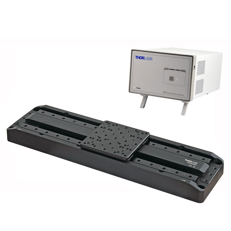
| Product Family | DDS Series 220 mm Stage |
DDS Series 300 mm Stage |
DDS Series 600 mm Stage |
| Click Photo to Enlarge |  |
 |
 |
| Travel | 220 mm | 300 mm | 600 mm |
| Maximum Velocity | 300 mm/s | 400 mm/s | 400 mm/s |
| Possible Axis Configurations | X, XY | X | X |
| Additional Details | |||

 Zoom
ZoomCharacterized by high-speed translation and high positional accuracy, the DDS300 stage is well suited for surface mapping and characterization applications where there is a need to move a camera or probe at constant velocity while simultaneously capturing data.
The BBD201 DC servo controller included in the package incorporates Thorlabs' standard apt™ control and programming interface, enabling easy integration into automated motion control applications. For greater flexibility, both a USB and RS232 (9-Pin) computer interface is provided, and automated PC control of the stage is supported with the supplied software development kit (SDK). The fully documented SDK supports all major development languages running on Windows (LabVIEW, C++, C#, etc.) and comes in the form of ActiveX libraries or a conventional dynamic link library (DLL).
USB connectivity provides easy plug-and-play PC operation. Multiple units can be connected to a single PC via standard USB hub technology for multi-axis motion control applications. Combining this feature with the user-friendly apt™ software allows the user to program and carry out complex move sequences in a short space of time. For more information, please see the full Brushless DC Servo Motor Controller presentation.
Very precise, fine positioning and control can be achieved with the associated MJC001 joystick option (described below).
Usage Notes
These stages are not suitable for operation in a vertical (Z-axis) orientation. When no power is applied, the platform of the stage has very little inertia and is virtually free running. This may make the stage unsuitable for applications where the stage's platform needs to remain in a set position when power is off.

 Zoom
Zoom![]()
Click to Enlarge
The deck height of the DDS300 Stage is matched to the MAX311D 3-Axis Stage using the DDSA04 Riser Plate.
- Height Adapter to Match the 62.5 mm Deck Height on Our NanoMax300, MicroBlock, and RollerBlock Stages
- Resulting Overall Optical Height: 75.0 mm (When Used with Thorlabs' Tongue and Groove Accessories)
- Array of 48 Tapped Holes (16 of Each): 1/4"-20 (M6), 8-32 (M4), and 4-40 (M3)
The DDSA04 Optical Height Adapter is designed to raise the deck height of the DDS300 stage to 62.5 mm, which is the same as our NanoMax 300, MicroBlock, and RollerBlock stages. This allows our range of tongue and groove optical accessories to be used with the DDS300 stage and gives an optical axis height of 75.0 mm. The plate is fixed to the moving platform of the stage using four 1/4"-20 x 3/8" (M6 x 10 mm) cap screws (not supplied).

 Zoom
Zoom
- High-Reliability Hall Effect Joystick
- Proportional Movement for Fast or High Precision Moves
- High/Low Speed Selection Button
- Speed Dial for Sensitivity Adjustment
- Ergonomic and Elegant Design
- High-Quality Machined Anodized Aluminum Casing
The MJC001 joystick console has been designed to provide intuitive, tactile, manual positioning of a stage. In most applications, the default parameter settings saved within the controller allow the joystick to be used out-of-the-box, with no need for further setup, thereby eliminating the need to be connected to a host PC and allowing true remote operation. For control of a single-axis stage, simply connect the console to the BBD201 controller. To control two stages simultaneously using the joy stick, a multi-axis BBD202 or BBD203 controller is required. This joystick is also compatible with our Rack-Mounted Brushless Controller and Stepper Motor Controllers. Please contact Tech Support for more details.