 Products Home / Optical Fiber & Fiber Patch Cables / Multimode Fiber Optic Patch Cables / MIR Multimode Fluoride Fiber Optic Patch Cables
MIR Multimode Fluoride Fiber Optic Patch Cables

- Transmissive in the UV, Visible, NIR, and MIR
- SMA905 or FC/PC-Compatible Connectors
- 1 m and 2 m Lengths
- Vacuum Compatible Patch Cables Available
MF12L2
Ø100 µm InF3
FC/PC-Compatible Connectors
MZ41L1
Ø450 µm ZrF4
SMA905 Connectors
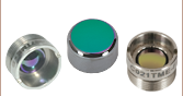
Included Caps
Included Caps


Please Wait

Click to Enlarge
Click for Raw Data
Zirconium fluoride (ZrF4) fiber offers flatter attenuation than indium fluoride (InF3) fiber in the MIR, while InF3 fiber is transparent at longer wavelengths than ZrF4 fiber. The silica fiber typically used in patch cables is not MIR-transparent. For information on run-to-run variations, please see the Graphs tab.
| MIR Fluoride Fiber Selection Guide |
|---|
| Single Mode Patch Cables |
| Multimode Patch Cables |
| Vacuum-Compatible Multimode Patch Cables |
| Bifurcated Fiber Bundles |
| Reflection/Backscatter Probe Bundles |
| MIR Fiber Overview |

Features
- Indium Fluoride (InF3) for 310 nm - 5.5 µm or
ZBLAN Zirconium Fluoride (ZrF4) for 285 nm - 4.5 µm- InF3 Core Size: Ø100 µm or Ø200 µm
- ZrF4 Core Size: Ø100 µm, Ø200 µm, Ø450 µm, or Ø600 µm
- Vacuum-Compatible Ø100 µm Core InF3 Cables Available
- Compatible with Visible-Wavelength Alignment Beams
- Used in Spectroscopy, Infrared Countermeasure (IRCM) Systems, and Medicine
- Low Fresnel Reflectance Losses: <4% per Face
Our IRphotonics® line of multimode fluoride patch cables are designed for low-loss transmission in the mid-IR spectral range. Manufactured using Thorlabs' fluoride optical fiber, our indium fluoride (InF3) patch cables have a transmission range of 310 nm - 5.5 µm, while our ZBLAN zirconium fluoride (ZrF4) patch cables have a transmission range of 285 nm - 4.5 µm. The graph to the right compares ZrF4 fiber, InF3 fiber, and low-OH silica fiber.
These fluoride fiber patch cables offer mechanical flexibility similar to standard silica patch cables, good environmental stability, and a flat attenuation curve in the mid-IR (see the Specs tab for details). Because fluoride glass transmits down into the UV, visible light (such as that generated by fiber-coupled lasers) can be propagated along the same fiber as an alignment aid. The numerical aperture (NA) of the patch cables remains relatively constant over their specified attenuation ranges (see the Graphs tab).

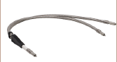
Both ends of each cable are terminated using metal ferrule connectors that are compatible with SMA905- or FC/PC-terminated components, respectively (see the FC Connectors tab for more details). We offer a vacuum-compatible Ø100 µm core InF3 patch cable that is usable down to 1 x 10⁻⁸ Torr. Each cable includes two protective caps that shield the ferrule ends from dust and other hazards. Replacement CAPF (plastic) and CAPFM (metal) caps for FC/PC-compatible cables or CAPM (rubber) and CAPSM (metal) caps for SMA905-terminated cables are available separately.
For spectroscopy and illumination applications, Thorlabs also manufactures bifurcated fluoride fiber bundles with 2 fibers.
Usage Recommendations
Since fluoride glass is softer than standard silica glass, Kimwipes®† should not be used to clean these patch cables. Please see the Handling tab for other fluoride-fiber-specific usage tips. Compared to unterminated fiber, the maximum power that these cables can withstand is limited by the connectors. Depending on the application, we recommend using these cables with a maximum CW power of approximately 300 mW.
†Kimwipes® is a registered trademark of the Kimberly-Clark Corporation.
Mid-IR Applications
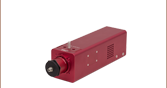
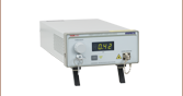
Because of their wide transmission range and flat attenuation, these patch cables are ideal for our Quantum Cascade Lasers (QCLs) and Interband Cascade Lasers (ICLs), which offer either broadband or single-wavelength emission in the MIR range. They are also well matched to our SLS202L Stabilized Light Source, which provides a blackbody radiation spectrum that spans from the visible into the mid-IR. Our Ø100 µm core patch cables are recommended for use with our Optical Spectrum Analyzers. Other application examples are shown by the photos below.

Click to Enlarge
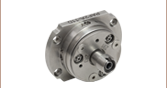
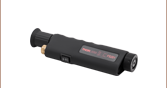
Fluoride patch cables can be connected to our MIR photodetectors using fiber adapters.

Click to Enlarge
The 310 nm - 5.5 µm wavelength range of InF3 patch cables makes them ideal for illumination applications that use our Stabilized Light Sources.

Click to Enlarge
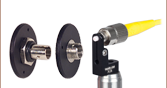
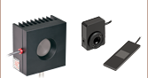
In this setup, a ZrF4 patch cable is used to propagate MIR light into a sample chamber for gas-phase spectroscopy. (More information on the pictured setup is available here.)
| In-Stock Multimode Fiber Optic Patch Cable Selection | ||||||
|---|---|---|---|---|---|---|
| Step Index | Graded Index | Fiber Bundles |
||||
| Uncoated | Coated | Mid-IR | Optogenetics | Specialized Applications | ||
| SMA FC/PC FC/PC to SMA Square-Core FC/PC and SMA |
AR-Coated SMA HR-Coated FC/PC Beamsplitter-Coated FC/PC |
Fluoride FC and SMA | Lightweight FC/PC Lightweight SMA Rotary Joint FC/PC and SMA |
High-Power SMA UHV, High-Temp. SMA Armored SMA Solarization-Resistant SMA |
FC/PC FC/PC to LC/PC |
|
Bare Fiber Specifications
| Cable Item # Prefix |
Fiber | Operating Wavelength Rangea |
Attenuation (Click for Plot) |
Core Diameter |
Cladding Diameter |
Core/Clad Concentricity |
NAb | Bend Radius (Short Term/Long Term) |
|---|---|---|---|---|---|---|---|---|
| MF11 MF12 |
InF3 Multimode | 310 nm - 5.5 µm | ≤0.45 dB/m (for 2.0 - 4.6 µm) |
100 ± 2.0 µm | 192 ± 2.5 µm | ≤2.0 µm | 0.26 ± 0.02 @ 2.0 µm | ≥15 mm / ≥147 mm |
| MFV1 | ≥50.0 mmc / ≥147 mm | |||||||
| MF21 MF22 |
≤0.3 dB/m (for 2.0 - 4.6 µm) |
200 ± 10.0 µm | 290 ± 10.0 µm | ≤3.0 µm | ≥40 mm / ≥200 mm | |||
| MZ11 MZ12 |
ZrF4 Multimode | 285 nm - 4.5 µm | ≤0.2 dB/m (for 2.0 - 3.6 µm) |
100 ± 2.0 µm | 192 ± 2.5 µm | ≤2.0 µm | 0.20 ± 0.02 @ 2.0 µm | ≥25 mm / ≥147 mm |
| MZ21 MZ22 |
200 ± 10 µm | 290 ± 10 µm | ≤3.0 µm | ≥40 mm / ≥80 mm | ||||
| MZ41 MZ42 |
450 ± 15 µm | 540 ± 15 µm | ≤5.0 µm | ≥50 mmc / ≥125 mm | ||||
| MZ61 MZ62 |
≤0.25 dB/m (for 2.0 - 3.6 µm) |
600 ± 20 µm | 690 ± 20 µm | ≤10.0 µm | ≥75 mm / ≥160 mm |
This tab contains plots of the attenuation, numerical aperture, and refractive indices of our fluoride fiber as a function of wavelength.
The shaded regions in the plots below denote the specified wavelength range over which the cable is guaranteed to meet attenuation specifications. Our Ø100 µm InF3 patch cables offer ≤0.45 dB/m attenuation (≥90% transmission per meter) and our Ø200 µm InF3 patch cables offer ≤0.3 dB/m attenuation (≥93% transmission per meter) from 2.0 to 4.6 µm. In contrast, our Ø100 µm, Ø200 µm, and Ø450 µm core ZrF4 cables offer ≤0.2 dB/m attenuation (≥95% transmission per meter) from 2.0 to 3.6 µm, while our Ø600 µm core ZrF4 cables offer ≤0.25 dB/m attenuation (≥94% transmission per meter) from 2.0 to 3.6 µm. Out-of-band performance is not rigorously monitored during quality control and may vary from run to run.
We are continuously refining our processes for these new materials in order to reduce the variations between runs. If you are concerned that the fiber you receive will not satisfy your needs, please contact Tech Support for details on what is currently available.
Attenuation

Click to Enlarge
Click for Raw Data
This plot contains the measured attenuation from six independent draws of the Ø100 µm core InF3 fiber. Within the 2.0 - 4.6 µm range, the attenuation is largely consistent from run to run, while greater variation between runs is observed in the visible and NIR

Click to Enlarge
Click for Raw Data
This plot contains the measured attenuation from five independent draws of the Ø200 µm core InF3 fiber.

Click to Enlarge
Click for Raw Data
This plot contains the measured attenuation from five independent draws of the Ø200 µm core ZrF4 fiber. This data is representative of our Ø100 µm, Ø200 µm, and Ø450 µm core fibers.

Click to Enlarge
Click for Raw Data
This plot contains the measured attenuation from five independent draws of the Ø600 µm core ZrF4 fiber.
Numerical Aperture

Click to Enlarge
Click for Raw Data
These NA values were calculated using the refractive indices shown in the plot below.

Click to Enlarge
Click for Raw Data
These NA values were calculated using the refractive indices shown in the plot below.
Refractive Indices

Click to Enlarge
Click for Raw Data
These refractive indices were calculated using the Sellmeier equation. The Sellmeier coefficients used in the fit are given in the table below.

Sellmeier Equation
| Sellmeier Coefficients | ||
|---|---|---|
| Coefficient | Core | Cladding |
| u0 | 0.5522 | 0.705674 |
| u1 | 0.7483 | 0.515736 |
| u2 | 1.007 | 2.204519 |
| u3 | 0.043 | 0.087503 |
| u4 | 0.113 | 0.087505 |
| u5 | 16.186 | 23.80739 |
| A | 0.9621 | 1 |

Click to Enlarge
Click for Raw Data
These refractive indices were obtained by fitting the Sellmeier equation to measured data. The Sellmeier coefficients used in the fit are given in the table below.
Sellmeier Equation
| Sellmeier Coefficients | ||
|---|---|---|
| Coefficient | Core | Cladding |
| u0 | 0.47627338 | 0.68462594 |
| u1 | 0.76936893 | 0.4952746 |
| u2 | 5.01835497 | 1.4841315 |
| u3 | 0.0179549 | 0.0680833 |
| u4 | 0.11865093 | 0.11054856 |
| u5 | 43.64545759 | 24.4391868 |
| A | 1 | 1 |
This tab describes the key similarities and differences between standard silica patch cables and fluoride patch cables in day-to-day usage.
Physical Handling
Bending
For protection, the fluoride patch cables are jacketed with stiffer materials than those used with typical patch cables. Our Ø450 µm and Ø600 µm core ZrF4 cables have stainless steel jackets, while our Ø100 µm and Ø200 µm core InF3 and Ø100 µm and Ø200 µm core ZrF4 cables have plastic (PVDF polymer) jackets. The fiber will remain intact as long as the jacket is not forced to bend. The plastic jacket will become discolored if the bending limit is exceeded, while the stainless steel jacket provides a rigid minimum bend radius that will not allow the fiber to break. Please refer to the tables below for the specified bend radii.
Storage
Since fluoride glass is softer than standard silica glass, it scratches more easily. Hence, it is especially important to use the included protective caps to protect the end faces when the patch cable is not being used. Replacement CAPF (plastic) and CAPFM (metal) caps for FC/PC-compatible cables or CAPM (rubber) and CAPSM (metal) caps for SMA905-terminated cables can be purchased separately.
Cleaning
Use the FS201 Fiber Inspection Scope to examine the tip of the fiber. If particulates are present, first try removing them using a gentle flow of compressed air. If compressed air is insufficient, then our FCC-7020 Fiber Connector Cleaner or MC-5 Lens Tissues can be used to clean the tip.
Please note that Kimwipes®† are extremely likely to scratch the fiber tip and should not be used.
Repolishing Service
If the tip of the fiber becomes scratched, Thorlabs will repolish it free of charge (the customer is responsible for shipping to and from Thorlabs). Please contact Tech Support to make use of this service.
Environmental Considerations
Normal lab temperatures and humidities will not affect the integrity of the fiber. Prolonged, direct contact with liquid water or water vapor should be avoided.
End-of-Life Disposal
Thorlabs will accept and safely dispose of fluoride patch cables that you wish to discard. Please contact Tech Support before returning the cable. If you wish to dispose of the cable locally, please follow all applicable local laws and regulations, noting that the fluoride glass is composed primarily of barium fluoride with zirconium fluoride or indium fluoride.
†Kimwipes® is a registered trademark of the Kimberly-Clark Corporation.

FC-Terminated Fluoride Patch Cables have Flat-Polished Tips

Standard FC/PC Connectors have Domed Tips
When using standard silica fiber patch cables, FC/PC or FC/APC connectors are typically chosen because the PC and APC polishes provide domed tips that bring the cores of two mated patch cables into physical contact. This physical contact minimizes the connection loss at the cable-to-cable interface.
Since fluoride glass is softer than silica glass, the polishing procedures used for silica glass result in flat fiber tips. Depending upon the cable, the tip may also be slightly recessed with respect to the ferrule. Fluoride patch cable connectors are therefore neither FC/PC (where "PC" denotes Physical Contact) nor FC/APC (where "APC" denotes Angled Physical Contact). Hence, we denote these cables as either flat-polished FC or angle-polished FC.
The flat fiber tip does not affect applications where the fiber output is being coupled into free space. However, when making cable-to-cable connections with FC connectors, such as through a mating sleeve or a bulkhead, transmission losses can occur because the fiber cores may not be in physical contact. Because the gap between FC-terminated cables is smaller than the typical gap between SMA905-terminated cables (which use air-gap ferrules), these losses are usually negligible.
The images below show two- and three-dimensional representations of the tip of a finished fluoride patch cable.

Click to Enlarge
This image contains a two-dimensional surface profile of the tip of a Ø100 µm core, flat-polished FC fluoride patch cable. The X and Y axis units are displayed in microns. The dashed circles and lines are shown as a guide to the eye. The interface between the metal ferrule and the cable interior is visualized by a faint green circle inside the blue dashed circle. This data is representative of all our flat-polished FC fluoride fiber patch cables.

Click to Enlarge
This image contains a three-dimensional map of the tip of a Ø100 µm core, flat-polished FC fluoride patch cable. The dashed circles are shown as a guide to the eye. The interface between the metal ferrule and the cable interior is represented by the round depression between the black and blue circles. This data is representative of all our flat-polished FC fluoride fiber patch cables.

Click to Enlarge
Total Internal Reflection in an Optical Fiber
Guiding Light in an Optical Fiber
Optical fibers are part of a broader class of optical components known as waveguides that utilize total internal reflection (TIR) in order to confine and guide light within a solid or liquid structure. Optical fibers, in particular, are used in numerous applications; common examples include telecommunications, spectroscopy, illumination, and sensors.
One of the more common glass (silica) optical fibers uses a structure known as a step-index fiber, which is shown in the image to the right. Step-index fibers have an inner core made from a material with a refractive index that is higher than the surrounding cladding layer. Within the fiber, a critical angle of incidence exists such that light will reflect off the core/cladding interface rather than refract into the surrounding medium. To fulfill the conditions for TIR in the fiber, the angle of incidence of light launched into the fiber must be less than a certain angle, which is defined as the acceptance angle, θacc. Snell's law can be used to calculate this angle:
![]()

where ncore is the refractive index of the fiber core, nclad is the refractive index of the fiber cladding, n is the refractive index of the outside medium, θcrit is the critical angle, and θacc is the acceptance half-angle of the fiber. The numerical aperture (NA) is a dimensionless quantity used by fiber manufacturers to specify the acceptance angle of an optical fiber and is defined as:

In step-index fibers with a large core (multimode), the NA can be calculated directly using this equation. The NA can also be determined experimentally by tracing the far-field beam profile and measuring the angle between the center of the beam and the point at which the beam intensity is 5% of the maximum; however, calculating the NA directly provides the most accurate value.
Number of Modes in an Optical Fiber
Each potential path that light propagates through in an optical fiber is known as a guided mode of the fiber. Depending on the physical dimensions of the core/cladding regions, refractive index, and wavelength, anything from one to thousands of modes can be supported within a single optical fiber. The two most commonly manufactured variants are single mode fiber (which supports a single guided mode) and multimode fiber (which supports a large number of guided modes). In a multimode fiber, lower-order modes tend to confine light spatially in the core of the fiber; higher-order modes, on the other hand, tend to confine light spatially near the core/cladding interface.
Using a few simple calculations, it is possible to estimate the number of modes (single mode or multimode) supported by an optical fiber. The normalized optical frequency, also known as the V-number, is a dimensionless quantity that is proportional to the free space optical frequency but is normalized to guiding properties of an optical fiber. The V-number is defined as:
![]()
where V is the normalized frequency (V-number), a is the fiber core radius, and λ is the free space wavelength. Multimode fibers have very large V-numbers; for example, a Ø50 µm core, 0.39 NA multimode fiber at a wavelength of 1.5 µm has a V-number of 40.8.
For multimode fiber, which has a large V-number, the number of modes supported is approximated using the following relationship.
![]()
In the example above of the Ø50 µm core, 0.39 NA multimode fiber, it supports approximately 832 different guided modes that can all travel simultaneously through the fiber.
Single mode fibers are defined with a V-number cut-off of V < 2.405, which represents the point at which light is coupled only into the fiber's fundamental mode. To meet this condition, a single mode fiber has a much smaller core size and NA compared to a multimode fiber at the same wavelength. One example of this, SMF-28 Ultra single mode fiber, has a nominal NA of 0.14 and an Ø8.2 µm core at 1550 nm, which results in a V-number of 2.404.

Click to Enlarge
Attenuation Due to Macrobend Loss

Click to Enlarge
Attenuation Due to Microbend Loss

Click to Enlarge
Beam profile measurement of FT200EMT multimode fiber and a former generation M565F1 LED (replaced by the M565F3) showing light guided in the cladding rather than the core of the fiber.
Sources of Attenuation
Loss within an optical fiber, also referred to as attenuation, is characterized and quantified in order to predict the total transmitted power lost within a fiber optic setup. The sources of these losses are typically wavelength dependent and range from the material used in the fiber itself to bending of the fiber. Common sources of attenuation are detailed below:
Absorption
Because light in a standard optical fiber is guided via a solid material, there are losses due to absorption as light propagates through the fiber. Standard fibers are manufactured using fused silica and are optimized for transmission from 1300 nm to 1550 nm. At longer wavelengths (>2000 nm), multi-phonon interactions in fused silica cause significant absorption. Fluoride glasses such as ZrF4 and InF3 are used in manufacturing Mid-IR optical fibers primarily because they exhibit lower loss at these wavelengths. ZrF4 and InF3 fibers have a multi-phonon edge of ~3.6 µm and ~4.6 µm, respectively.
Contaminants in the fiber also contribute to the absorption loss. One example of an undesired impurity is water molecules that are trapped in the glass of the optical fiber, which will absorb light around 1300 nm and 2.94 µm. Since telecom signals and some lasers operate in that same region, any water molecules present in the fiber will attenuate the signal significantly.
The concentration of ions in the fiber glass is often controlled by manufacturers to tune the transmission/attenuation properties of a fiber. For example, hydroxyl ions (OH-) are naturally present in silica and absorb light in the NIR-IR spectrum. Therefore, fibers with low-OH content are preferred for transmission at telecom wavelengths. On the other hand, fibers with high-OH content typically exhibit increased transmission at UV wavelengths and thus may be preferred by users interested in applications such as fluorescence or UV-VIS spectroscopy.
Scattering
For the majority of fiber optics applications, light scattering is a source of loss that occurs when light encounters a change in the refractive index of the medium. These changes can be extrinsic, caused by impurities, particulates, or bubbles; or intrinsic, caused by fluctuations in the glass density, composition, or phase state. Scattering is inversely related to the wavelength of light, so scattering loss becomes significant at shorter wavelengths such as the UV or blue regions of the spectrum. Using proper fiber cleaning, handling, and storage procedures may minimize the presence of impurities on tips of fibers that cause large scattering losses.
Bending Loss
Losses that occur due to changes in the external and internal geometry of an optical fiber are known as bending loss. These are usually separated into two categories: macrobending loss and microbending loss.
Macrobend loss is typically associated with the physical bending of an optical fiber; for example, rolling it in a tight coil. As shown in the image to the right, guided light is spatially distributed within the core and cladding regions of the fiber. When a fiber is bent at a radius, light near the outer radius of the bend cannot maintain the same spatial mode profile without exceeding the speed of light. Instead, the energy is lost to the surroundings as radiation. For a large bend radius, the losses associated with bending are small; however, at bend radii smaller than the recommended bend radius of a fiber, bend losses become very significant. For short periods of time, optical fibers can be operated at a small bend radius; however, for long-term storage, the bend radius should be larger than the recommended value. Use proper storage conditions (temperature and bend radius) to reduce the likelihood of permanently damaging the fiber; the FSR1 Fiber Storage Reel is designed to minimize high bend loss.
Microbend loss arises from changes in the internal geometry of the fiber, particularly the core and cladding layers. These random variations (i.e., bumps) in the fiber structure disturb the conditions needed for total internal reflection, causing propagating light to couple into a non-propagating mode that leaks from the fiber (see the image to the right for details). Unlike macrobend loss, which is controlled by the bend radius, microbend loss occurs due to permanent defects in the fiber that are created during fiber manufacturing.
Cladding Modes
While most light in a multimode fiber is guided via TIR within the core of the fiber, higher-order modes that guide light within both the core and cladding layer, because of TIR at the cladding and coating/buffer interface, can also exist. This results in what is known as a cladding mode. An example of this can be seen in the beam profile measurement to the right, which shows cladding modes with a higher intensity in the cladding than in the core of the fiber. These modes can be non-propagating (i.e., they do not fulfill the conditions for TIR) or they can propagate over a significant length of fiber. Because cladding modes are typically higher-order, they are a source of loss in the presence of fiber bending and microbending defects. Cladding modes are also lost when connecting two fibers via connectors as they cannot be easily coupled between optical fibers.
Cladding modes may be undesired for some applications (e.g., launching into free space) because of their effect on the beam spatial profile. Over long fiber lengths, these modes will naturally attenuate. For short fiber lengths (<10 m), one method for removing cladding modes from a fiber is to use a mandrel wrap at a radius that removes cladding modes while keeping the desired propagating modes.
Launch Conditions
Underfilled Launch Condition
For a large multimode fiber which accepts light over a wide NA, the condition of the light (e.g., source type, beam diameter, NA) coupled into the fiber can have a significant effect on performance. An underfilled launch condition occurs when the beam diameter and NA of light at the coupling interface are smaller than the core diameter and NA of the fiber. A common example of this is launching a laser source into a large multimode fiber. As seen in the diagram and beam profile measurement below, underfilled launches tend to concentrate light spatially in the center of the fiber, filling lower-order modes preferentially over higher-order modes. As a result, they are less sensitive to macrobend losses and do not have cladding modes. The measured insertion loss for an underfilled launch tends to be lower than typical, with a higher power density in the core of the fiber.


Overfilled Launch Condition
Overfilled launches are defined by situations where the beam diameter and NA at the coupling interface are larger than the core diameter and NA of the fiber. One method to achieve this is by launching light from an LED source into a small multimode fiber. An overfilled launch completely exposes the fiber core and some of the cladding to light, enabling the filling of lower- and higher-order modes equally (as seen in the images below) and increasing the likelihood of coupling into cladding modes of the fiber. This increased percentage of higher-order modes means that overfilled fibers are more sensitive to bending loss. The measured insertion loss for an overfilled launch tends to be higher than typical, but results in an overall higher output power compared to an underfilled fiber launch.


There are advantages and disadvantages to underfilled or overfilled launch conditions, depending on the needs of the intended application. For measuring the baseline performance of a multimode fiber, Thorlabs recommends using a launch condition where the beam diameter is 70-80% of the fiber core diameter. Over short distances, an overfilled fiber has more output power; however, over long distances (>10 - 20 m) the higher-order modes that more susceptible to attenuation will disappear.
Thorlabs Lab Facts: Modifying Beam Profiles with Multimode Fibers
We present laboratory measurements demonstrating how the output beam profile from multimode fiber can be affected by the beam entry angle. In some applications, an alternative beam distribution such as a top hat or donut is desired instead of the inherent Gaussian distribution provided by typical optics. Here we investigated the effect of changing the input angle of a focused laser beam into a multimode fiber patch cable. Focusing the light normal to the fiber face produced a near-Gaussian output beam profile (Figure 1) and increasing the angle resulted in top hat- (Figure 2) and donut-shaped (Figure 3) beam profiles. These results demonstrate how multimode fibers can be used to change the shape of a beam profile.
For our experiment, we used an M38L01 Ø200 µm, 0.39 NA, Step-Index Fiber Patch Cable (Bare Fiber Item # FT200EMT) as the test fiber into which we launched the focused laser beam. The input light was set incident at 0°, 11°, and 15° to the input face of the multimode fiber to create the initial, top hat, and donut profiles, respectively. Each time the angle was changed, the alignment of the input fiber was optimized while the output power was monitored with a power meter to ensure maximum coupling was achieved. Images were then acquired with a 9 second exposure and the shape of the beam profile was evaluated. Note that during the exposure, a 1500 grit diffuser was manually rotated between the coupling optics (before the fiber under test) to reduce the spatial coherence and create a clean output beam profile.

Assuming a ray tracing model, there are two general types of rays that propagate along a multimode fiber: (a) meridional rays, which pass through the central axis of the fiber after each reflection, and (b) skew rays, which never pass through the central axis of the fiber. The figures below illustrate the three basic ray propagation scenarios observed during the experiment. Figures 4 and 6 depict meridional and skew ray propagation through multimode fiber, respectively, and the associated theoretical beam distribution at the fiber output. As illustrated in Figure 6, skew rays propagate in a helical path along the fiber that is tangent to the inner caustic of the path with radius r. Figure 5 depicts the beam propagation and beam distribution from a combination of meridional and skew rays. By changing the input angle of the light launched into a multimode fiber, we were able to modify the proportion of light rays propagating as meridional rays vs. skew rays, and consequently, modify the output from a near-Gaussian distribution (primarily meridional rays, see Figure 1) to a top hat (mixture of meridional and skew rays, see Figure 2) to a donut (primarily skew rays, see Figure 3). The beam profiles shown in Figures 4 through 6 were obtained at a distance of 5 mm from the fiber end face. These results demonstrate the ability to use a standard multimode fiber patch cable as a relatively inexpensive method to modify an input Gaussian profile into a top hat and donut profile with minimal loss. For details on the experimental setup employed and these summarized results, please click here.

Figure 1. Near-Gaussian Beam Profile
Obtained at 0° Input Angle (Normal to Fiber Face)

Figure 3. Donut Beam Profile
Obtained at 15° Input Angle

Figure 2. Top Hat Beam Profile
Obtained at 11° Input Angle


| Posted Comments: | |
Simon Hicks
(posted 2020-11-30 09:54:46.283) Hi, I need the bandwidth of the InF3 fibers, but they only seem to come with core diameters of 100 or 200um. Can you supply them with core diameters of 400 or 600um?
Thanks YLohia
(posted 2020-12-01 10:29:51.0) Thank you for contacting Thorlabs. Custom versions of these can be requested by emailing techsupport@thorlabs.com. We will discuss the possibility of offering this customization directly. michael.vollero
(posted 2018-11-28 14:57:41.78) What is the reason that the InF3 patch cables are only rated up to 90 degC? nbayconich
(posted 2018-12-04 02:58:40.0) Thank you for contacting Thorlabs. The temperature limitation of the patch cables will be limited by the furcation tubing, epoxy and connector ends. The bare InF3 fiber itself will typically have a lower operating temperature than bare silica fiber. I will reach out to you directly with more information. tarabrinmike
(posted 2018-08-13 15:31:05.613) Hello, how it's possible to launch over 2 W of MIR radiation of laser into fluoride fiber if connectors can handle only 300 mW? In that case core diameter doesn't matter YLohia
(posted 2018-08-13 04:11:04.0) Hello, unfortunately, it is not recommended to couple 2 Watts of power into connectorized fiber patch cables. We recommend cutting off the connector for high power coupling in this case. alan.marchant
(posted 2017-07-17 12:27:43.277) I'm confused by the bend curvature specifications. The minimum long-term bend radius for the 100 um core fibers are specified at 155 mm, much larger than for the 200 um core fibers (80 mm), defying intuition. Can you confirm or correct these values? To select the best fiber for my application, I need confidence in this specifications. tfrisch
(posted 2017-08-11 10:47:49.0) Hello, thank you for contacting Thorlabs. We are working on updating the bend radius specs since our initial values were quite conservative. 200um is the first to be corrected, and others will be listed as we gather data. patrick.nau
(posted 2014-10-31 15:56:57.697) Hi,
I want to use this fiber in combination with a DFB diode lase. Are these fibers also available with a FC/APC connector to reduce optical feedback?
Thank you very much jlow
(posted 2014-11-03 03:51:19.0) Response from Jeremy at Thorlabs: We do not have the FC/APC connector available for these multimode fiber because of the cladding size. However, we do have the angle polished FC available for single mode MIR fiber at https://www.thorlabs.com/newgrouppage9.cfm?objectgroup_ID=7999. |

 Zoom
Zoom
Click to Enlarge
Each fluoride patch cable is labeled with its item #, key specifications, and batch number.
- SMA905 or FC/PC-Compatible Connectors with Metal Ferrules
- Stocked in 1 m and 2 m Lengths
- Custom Lengths Available by Contacting Tech Support
- Stiff, Ø3.0 mm Plastic Jacket
- Two Protective Caps Included
- SMA905-Terminated Cables: Stainless Steel Caps
- FC/PC-Compatible Cables: Plastic Caps
| Item # Prefix |
Fiber | Operating Rangea |
Attenuation (Click for Plot) |
Core Diameter |
Cladding Diameter |
NAb | Bend Radius (Short Term/ Long Term) |
Connectors | Jacket | Operating Temp. |
|---|---|---|---|---|---|---|---|---|---|---|
| MF11 | InF3 Multimode | 310 nm - 5.5 µm | ≤0.45 dB/m (for 2.0 - 4.6 µm) |
100 ± 2.0 µm | 192 ± 2.5 µm | 0.26 ± 0.02 @ 2.0 µm |
≥15 mm / ≥147 mm |
SMA905 | Blue PVDF (Ø3 mm) |
-55 to 90 °C |
| MF12 | FC/PC-Compatiblec |

 Zoom
Zoom
Click to Enlarge
Bottom View of MFV1L1 Fiber End

Click to Enlarge
Top View of MFV1L1 Fiber End
Each fluoride patch cable is engraved with its item # and key specifications. The batch number is given on a separate white sleeve.
- Hermetically Sealed Multimode Step-Index Fiber
- Construction Enables use at Vacuum Pressures Down to 1 x 10⁻⁸ Torr
- SMA905 Connectors with Metal Ferrules
- Stocked in 1 m Lengths
- Ø5.2 mm 304 Stainless Steel Jacket
- Two Protective Caps Included
To complement the MFV1L1 patch cable, we also offer a KF40 flange fiber feedthrough that uses Ø100 µm InF3 multimode fiber (Item # VK4F1S). The two can be mated using a vacuum-compatible SMA mating sleeve, such as the ADASMAV.
| Item # | Fiber | Operating Rangea |
Attenuation | Core Diameter |
Cladding Diameter |
NAb | Bend Radius (Short Term/ Long Term) |
Connectors | Jacket | Temperature Rating |
Temperature Ramp |
|---|---|---|---|---|---|---|---|---|---|---|---|
| MFV1L1 | InF3 Multimodec | 310 nm - 5.5 µm | ≤0.45 dB/m (for 2.0 - 4.6 µm) |
100 ± 2.0 µm | 192 ± 2.5 µm | 0.26 ± 0.02 @ 2.0 µm |
≥50.0 mmd / ≥147 mm |
SMA905 | Ø5.2 mm Stainless Steel Interlock Tubing |
90 °Ce 75 °Cf |
10 °C / minute (Max) |

 Zoom
Zoom
Click for Details
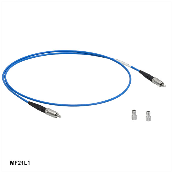
Each fluoride patch cable is labeled with its item #, key specifications, and batch number.
- SMA905 or FC/PC-Compatible Connectors with Metal Ferrules
- Stocked in 1 m and 2 m Lengths
- Custom Lengths Available by Contacting Tech Support
- Stiff, Ø3.0 mm Plastic Jacket
- Two Protective Caps Included
- SMA905-Terminated Cables: Stainless Steel Caps
- FC/PC-Compatible Cables: Plastic Caps
| Item # Prefix |
Fiber | Operating Rangea |
Attenuation (Click for Plot) |
Core Diameter |
Cladding Diameter |
NAb | Bend Radius (Short Term/ Long Term) |
Connectors | Jacket | Operating Temperature |
|---|---|---|---|---|---|---|---|---|---|---|
| MF21 | InF3 Multimode | 310 nm - 5.5 µm | ≤0.3 dB/m (for 2.0 - 4.6 µm) |
200 ± 10.0 µm | 290 ± 10.0 µm | 0.26 ± 0.02 @ 2.0 µm |
≥40 mm / ≥200 mm | SMA905 | Blue PVDF (Ø3 mm) |
-55 to 90 °C |
| MF22 | FC/PC-Compatiblec |

 Zoom
Zoom
Click for Details
Each fluoride patch cable is labeled with its
item #, key specifications, and batch number.
- SMA905 or FC/PC-Compatible Connectors with Metal Ferrules
- Stocked in 1 m and 2 m Lengths
- Custom Lengths Available by Contacting Tech Support
- Stiff, Ø3.0 mm Plastic Jacket
- Two Protective Caps Included
- SMA905-Terminated Cables: Stainless Steel Caps
- FC/PC-Compatible Cables: Plastic Caps
| Item # Prefix |
Fiber | Operating Rangea |
Attenuation (Click for Plot) |
Core Diameter |
Cladding Diameter |
NAb | Bend Radius (Short Term/ Long Term) |
Connectors | Jacket | Operating Temperature |
|---|---|---|---|---|---|---|---|---|---|---|
| MZ11 | ZrF4 Multimode | 285 nm - 4.5 µm | ≤0.2 dB/m (for 2.0 - 3.6 µm) |
100 ± 2.0 µm | 192 ± 2.5 µm | 0.20 ± 0.02 @ 2.0 µm |
≥25 mm / ≥147 mm | SMA905 | Blue PVDF (Ø3 mm) |
-55 to 90 °C |
| MZ12 | FC/PC-Compatiblec |

 Zoom
Zoom
Click for Details
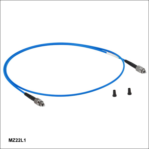
Each fluoride patch cable is labeled with its item #, key specifications, and batch number.
- SMA905 or FC/PC-Compatible Connectors with Metal Ferrules
- Stocked in 1 m and 2 m Lengths
- Custom Lengths Available by Contacting Tech Support
- Stiff, Ø3.0 mm Plastic Jacket
- Two Protective Caps Included
- SMA905-Terminated Cables: Stainless Steel Caps
- FC/PC-Compatible Cables: Plastic Caps
| Item # Prefix |
Fiber | Operating Rangea |
Attenuation (Click for Plot) |
Core Diameter |
Cladding Diameter |
NAb | Bend Radius (Short Term/ Long Term) |
Connectors | Jacket | Operating Temperature |
|---|---|---|---|---|---|---|---|---|---|---|
| MZ21 | ZrF4 Multimode | 285 nm - 4.5 µm | ≤0.2 dB/m (for 2.0 - 3.6 µm) |
200 ± 10 µm | 290 ± 10 µm | 0.20 ± 0.02 @ 2.0 µm |
≥40 mm / ≥80 mm | SMA905 | Blue PVDF (Ø3 mm) |
-55 to 90 °C |
| MZ22 | FC/PC-Compatiblec |

 Zoom
Zoom
Click for Details
Bottom View of Fiber End

Click for Details
Top View of Fiber End
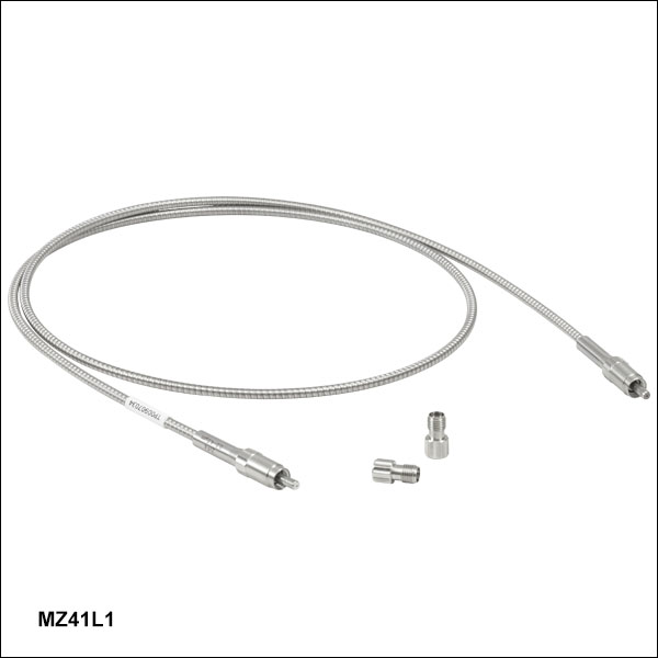
Each fluoride patch cable is engraved with its item # and key specifications. The batch number is given on a separate white sleeve.
- SMA905 or FC/PC-Compatible Connectors with Metal Ferrules
- Stocked in 1 m Lengths
- Custom Lengths Available by Contacting Tech Support
- Ø3.8 mm Stainless Steel Jacket with Minimum Bend Radius of 50 mm
- Two Protective Caps Included
- SMA905-Terminated Cables: Stainless Steel Caps
- FC/PC-Compatible Cables: Plastic Caps
| Item # | Fiber | Operating Rangea |
Attenuation (Click for Plot) |
Core Diameter |
Cladding Diameter |
NAb | Bend Radius (Short Termc/ Long Term) |
Connectors | Jacket | Operating Temperature |
|---|---|---|---|---|---|---|---|---|---|---|
| MZ41L1 | ZrF4 Multimode | 285 nm - 4.5 µm | ≤0.2 dB/m (for 2.0 - 3.6 µm) |
450 ± 15 µm | 540 ± 15 µm | 0.20 ± 0.02 @ 2.0 µm |
≥50 mm / ≥125 mm | SMA905 | Stainless Steel (Ø3.8 mm) |
-55 to 90 °C |
| MZ42L1 | FC/PC-Compatibled |

 Zoom
Zoom

Click for Details
Bottom View of Fiber End

Click for Details
Top View of Fiber End
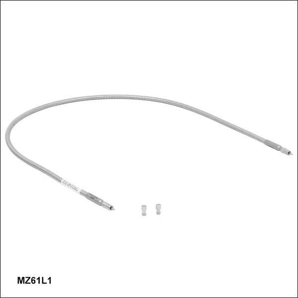
Each fluoride patch cable is engraved with its item # and key specifications. The batch number is given on a separate white sleeve (not shown).
- SMA905 or FC/PC-Compatible Connectors with Metal Ferrules
- Stocked in 1 m Lengths
- Custom Lengths Available by Contacting Tech Support
- Ø8.0 mm Stainless Steel Jacket with Minimum Bend Radius of 140 mm
- Two Protective Caps Included
- SMA905-Terminated Cables: Stainless Steel Caps
- FC/PC-Compatible Cables: Plastic Caps
| Item # | Fiber | Operating Rangea |
Attenuation (Click for Plot) |
Core Diameter |
Cladding Diameter |
NAb | Bend Radius (Short Term/ Long Term) |
Connectors | Jacket | Operating Temperature |
|---|---|---|---|---|---|---|---|---|---|---|
| MZ61L1 | ZrF4 Multimode | 285 nm - 4.5 µm | ≤0.25 dB/m (for 2.0 - 3.6 µm) |
600 ± 20 µm | 690 ± 20 µm | 0.20 ± 0.02 @ 2.0 µm |
≥75 mm / ≥160 mm | SMA905 | Stainless Steel (Ø8.0 mm) |
-55 to 90 °C |
| MZ62L1 | FC/PC-Compatiblec |