 Products Home / Optical Fiber & Fiber Patch Cables / Single Mode Fiber Optic Patch Cables / MIR Single Mode Fluoride Fiber Optic Patch Cables
MIR Single Mode Fluoride Fiber Optic Patch Cables
- SM Fluoride Patch Cables for 2.3 - 4.1 µm or 3.2 - 5.5 µm
- FC/PC- or FC/APC-Compatible Connectors
- 1 m, 2 m, or 5 m Lengths
P3-23Z-FC-2
ZrF4 Fiber, FC/APC-Compatible Connectors
P1-32F-FC-1
InF3 Fiber, FC/PC-Compatible Connectors


Please Wait

Click to Enlarge
Zirconium fluoride (ZrF4) fiber offers lower attenuation than indium fluoride (InF3) fiber, while InF3 fiber is transparent at longer wavelengths than ZrF4 fiber. For additional attenuation plots, please see the Graphs tab.
| MIR Fluoride Fiber Selection Guide |
|---|
| Single Mode Patch Cables |
| Multimode Patch Cables |
| Vacuum-Compatible Multimode Patch Cables |
| Bifurcated Fiber Bundles |
| Reflection/Backscatter Probe Bundles |
| MIR Fiber Overview |

| Stocked SM Patch Cable Selection Guide | |
|---|---|
| Standard Silica Cables | FC/PC to FC/PC |
| FC/APC to FC/APC | |
| Hybrid | |
| AR-Coated Silica | |
| AR-Coated TEC Silica | |
| HR-Coated Silica | |
| Beamsplitter-Coated Silica | |
| Low-Insertion-Loss Silica | |
| MIR Fluoride Fiber | |
Features
- Single Mode Operation from 2.3 µm to 4.1 µm for Zirconium Fluoride (ZrF4)
or 3.2 µm to 5.5 µm for Indium Fluoride (InF3) - Transmission from 285 nm to 4.5 µm for Zirconium Fluoride (ZrF4)
or 310 nm to 5.5 µm for Indium Fluoride (InF3) - Compatible with Visible-Wavelength Alignment Beams
- Used in Spectroscopy, Environmental Sensing, and Medicine
- Low Fresnel Reflectance Losses: <4% per Face
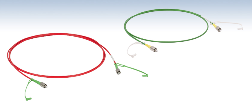
Our IRphotonics® line of single mode fluoride patch cables are designed for low-loss transmission in the mid-IR spectral range. Manufactured using Thorlabs' fluoride optical fiber, our ZBLAN zirconium fluoride (ZrF4) patch cables have a single mode operation range of 2.3 - 4.1 µm, while our indium fluoride (InF3) patch cables have a single mode operation range of 3.2 - 5.5 µm. See the graph on the right for a comparison of ZrF4 fiber and InF3 fiber attenuation.
These fluoride fiber patch cables offer mechanical flexibility similar to standard silica patch cables, good environmental stability, and a flat attenuation curve in the mid-IR. Because fluoride glass transmits down into the UV, visible light (such as that generated by fiber-coupled lasers) can be propagated along the same fiber as an alignment aid. Note that because visible light is below the cutoff wavelength, it will propagate as if in a multimode fiber. The numerical aperture (NA) of these patch cables remains relatively constant over the specified SM operating range (see the Graphs tab for plots).

Click for Details
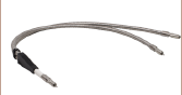
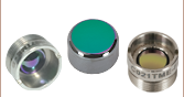
Each fluoride patch cable is labeled with its Item #, batch number, and key specifications.
Both ends of each cable are terminated using ceramic ferrule connectors, with flat or angled polishes that are compatible with either FC/PC- or FC/APC-terminated components, respectively (see the FC Connectors tab for more details). In setups that are sensitive to back reflections, we recommend using angled FC connectors. Each cable includes two protective caps that shield the ferrule ends from dust and other hazards. Replacement CAPF (plastic) and CAPFM (metal) caps are available separately.
Usage Recommendations
Since fluoride glass is softer than standard silica glass, Kimwipes®† should not be used to clean these patch cables. Please see the Handling tab for other fluoride-fiber-specific usage tips. Compared to unterminated fiber, the maximum power that these cables can withstand is limited by the connectors. Depending on the application, we recommend using these cables with a maximum CW power of approximately 300 mW.
Mid-IR Applications
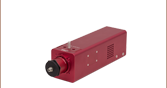
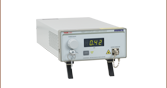
Because the SM operation range overlaps with the emission range of our Interband Cascade Lasers (ICLs), low-loss measurements of the laser output spectrum are possible using these cables in combination with our Optical Spectrum Analyzers. Other application examples are shown by the photos below.

Click to Enlarge
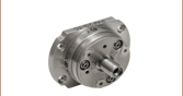
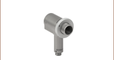
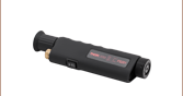
Signals in SM fluoride patch cables can be coupled into free space using a reflective collimator.

Click to Enlarge
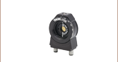
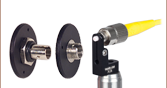
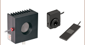
As an alternative to reflective collimators, FiberPorts offer free-space coupling with five degrees of freedom, plus rotational adjustment.
†Kimwipes® is a registered trademark of the Kimberly-Clark Corporation.
| Bare Fiber Specifications | ||
|---|---|---|
| Fiber | ZrF4 Single Mode | InF3 Single Mode |
| Transmission Range | 285 nm - 4.5 µm | 310 nm - 5.5 µm |
| SM Operating Wavelength Range | 2.3 - 4.1 µm | 3.2 - 5.5 µm |
| Attenuation (Click for Plot) | ≤0.3 dB/m (Max); 0.15 dB/m (Typical) (for 2.3 - 3.6 µm) |
≤0.45 dB/m (Max) (for 3.2 - 4.6 µm) |
| Mode Field Diametera (Click for Plot) | 10.75 µm @ 2.5 µm; 14.80 µm @ 3.39 µm | 10.66 µm @ 3.39 µm |
| Cutoff Wavelength | ≤2.3 µm | ≤3.2 µm |
| Numerical Aperture (NA)b | 0.19 ± 0.02 @ 2.0 µm | 0.26 ± 0.02 @ 2.0 µm |
| Core Diameter | 9 ± 0.5 µm | |
| Cladding Diameter | 125 +1/-2 µm | |
| Core/Clad Concentricity | ≤2.0 µm | |
| Bend Radius (Short Term/Long Term) | ≥10 mm / ≥40 mm | ≥10 mm / ≥30 mm |
This tab contains plots of the attenuation (measured), bend-induced attenuation (measured), dispersion (calculated), numerical aperture (measured) and refractive indices (measured) of our fluoride fiber as a function of wavelength. The data files linked below each graph also provide calculated data for the mode field diameter as a function of wavelength.
The data shown below is for a single patch cable; variations between cables can occur. Please contact Tech Support if you have concerns about whether these fibers are appropriate for your application.
Attenuation

Click to Enlarge
Click for Raw Data
This plot contains the measured attenuation for our single mode ZrF4 fiber. The green shaded region in the plot denotes the specified range for single mode operation with attenuation ≤0.3 dB/m, and the blue shaded region denotes the range for single mode operation without a guaranteed attenuation specification. The orange shaded region denotes the range where the fiber is still transmissive, but provides multimode operation.The cutoff wavelength, denoted by a dashed vertical line, is the onset of this multimode operation and will vary from run to run. The peak near 1.9 µm corresponds to attenuation of the second-order mode.

Click to Enlarge
Click for Raw Data
This plot contains the measured attenuation for our single mode InF3 fiber. The green shaded region in the plot denotes the specified range for single mode operation with attenuation ≤0.45 dB/m, and the blue shaded region denotes the range for single mode operation without a guaranteed attenuation specification. The orange shaded region denotes the range where the fiber is still transmissive, but provides multimode operation. The cutoff wavelength, denoted by a dashed vertical line, is the onset of this multimode operation and will vary from run to run. The peak near 2.9 µm corresponds to attenuation of the second-order mode.

Click to Enlarge
Click for Raw Data
This plot contains the measured attenuation for a single loop of our single mode ZrF4 fiber at five different bend radii. The blue and green shaded regions in the plot together denote the single mode wavelength range (2.3 - 4.1 µm).

Click to Enlarge
Click for Raw Data
This plot contains the measured attenuation for a single loop of our single mode InF3 fiber at four different bend radii. The blue and green shaded regions in the plot together denote the single mode wavelength range (3.2 - 5.5 µm).
Dispersion

Click to Enlarge
Click for Raw Data
This plot contains the calculated chromatic dispersion of our single mode ZrF4 fiber. The zero-dispersion wavelength is around 1.6 µm. The shaded region in the plot denotes the single mode wavelength range (2.3 - 4.1 µm).

Click to Enlarge
Click for Raw Data
This plot contains the calculated chromatic dispersion of our single mode InF3 fiber. The zero-dispersion wavelength is around 1.7 µm. The shaded region in the plot denotes the single mode wavelength range (3.2 - 5.5 µm).
Numerical Aperture

Click to Enlarge
Click for Raw Data
This plot contains the NA values of our single mode ZrF4 fiber, based upon the refractive indices in the plot below. The shaded region in the plot denotes the single mode wavelength range (2.3 - 4.1 µm).

Click to Enlarge
Click for Raw Data
This plot contains the NA values of our single mode InF3 fiber, based upon the refractive indices in the plot below. The shaded region in the plot denotes the single mode wavelength range (3.2 - 5.5 µm).
Refractive Indices

Click to Enlarge
Click for Raw Data
The refractive indices shown here were obtained by fitting the Sellmeier equation to measured data. The Sellmeier coefficients used in the fit are given in the table to the right.
 Sellmeier Equation
| Sellmeier Coefficients | ||
|---|---|---|
| Coefficient | Core | Cladding |
| u0 | 0.5463 | 0.705674 |
| u1 | 0.7566 | 0.515736 |
| u2 | 1.782 | 2.204519 |
| u3 | 0.000 | 0.087503 |
| u4 | 0.116 | 0.087505 |
| u5 | 21.263 | 23.80739 |
| A | 0.9562 | 1 |

Click to Enlarge
Click for Raw Data
These refractive indices were obtained by fitting the Sellmeier equation to measured data. The Sellmeier coefficients used in the fit are given in the table below.
Sellmeier Equation
| Sellmeier Coefficients | ||
|---|---|---|
| Coefficient | Core | Cladding |
| u0 | 0.47627338 | 0.68462594 |
| u1 | 0.76936893 | 0.4952746 |
| u2 | 5.01835497 | 1.4841315 |
| u3 | 0.0179549 | 0.0680833 |
| u4 | 0.11865093 | 0.11054856 |
| u5 | 43.64545759 | 24.4391868 |
| A | 1 | 1 |
This tab describes the key similarities and differences between standard silica patch cables and fluoride patch cables in day-to-day usage.
Physical Handling
Bending
For protection, the fluoride patch cables are jacketed with plastic (PVDF polymer) that is stiffer than the jackets used with typical patch cables. As long as the jacket is not forced to bend, the fiber will remain intact. The plastic jacket will become discolored if the bending limit is exceeded. Please refer to the table below for the specified bend radius. For additional information on the effect of bend-induced attenuation in these fibers, please see the Graphs tab.
Storage
Since fluoride glass is softer than standard silica glass, it scratches more easily. Hence, it is especially important to use the included protective caps to protect the end faces when the patch cable is not being used. Replacement CAPF (plastic) and CAPFM (metal) caps can be purchased separately.
Cleaning
Use the FS201 Fiber Inspection Scope to examine the tip of the fiber. If particulates are present, first try removing them using a gentle flow of compressed air. If compressed air is insufficient, then our
Please note that Kimwipes®† are extremely likely to scratch the fiber tip and should not be used.
Repolishing Service
If the tip of the fiber becomes scratched, Thorlabs will repolish it free of charge (the customer is responsible for shipping to and from Thorlabs). Please contact Tech Support to make use of this service.
Environmental Considerations
Normal lab temperatures and humidities will not affect the integrity of the fiber. Prolonged, direct contact with liquid water or water vapor should be avoided.
End-of-Life Disposal
Thorlabs will accept and safely dispose of fluoride patch cables that you wish to discard. Please contact Tech Support before returning the cable. If you wish to dispose of the cable locally, please follow all applicable local laws and regulations, noting that the fluoride glass is composed primarily of barium fluoride with zirconium fluoride or indium fluoride.
†Kimwipes® is a registered trademark of the Kimberly-Clark Corporation.

Angled FC-Terminated Fluoride Patch Cables have 8° Angle-Polished Tips

FC-Terminated Fluoride Patch Cables have Flat-Polished Tips

Standard FC/PC Connectors have Domed Tips
When using standard silica fiber patch cables, FC/PC or FC/APC connectors are typically chosen because the PC and APC polishes provide domed tips that bring the cores of two mated patch cables into physical contact. This physical contact minimizes the connection loss at the cable-to-cable interface.
Since fluoride glass is softer than silica glass, the polishing procedures used for silica glass result in flat fiber tips. Depending upon the cable, the tip may also be slightly recessed with respect to the ferrule. Fluoride patch cable connectors are therefore neither FC/PC (where "PC" denotes Physical Contact) nor FC/APC (where "APC" denotes Angled Physical Contact). Hence, we denote these cables as either flat-polished FC or angle-polished FC.
The flat fiber tip does not affect applications where the fiber output is being coupled into free space. However, when making cable-to-cable connections with FC connectors, such as through a mating sleeve or a bulkhead, transmission losses can occur because the fiber cores may not be in physical contact. Because the gap between FC-terminated cables is smaller than the typical gap between SMA905-terminated cables (which use air-gap ferrules), these losses are usually negligible.
The images below show two- and three-dimensional representations of the tip of a finished fluoride patch cable.

Click to Enlarge
This image contains a two-dimensional surface profile of the tip of a Ø100 µm core, flat-polished FC fluoride patch cable. The X and Y axis units are displayed in microns. The dashed circles and lines are shown as a guide to the eye. The interface between the metal ferrule and the cable interior is visualized by a faint green circle inside the blue dashed circle. This data is representative of all our flat-polished FC fluoride fiber patch cables.

Click to Enlarge
This image contains a three-dimensional map of the tip of a Ø100 µm core, flat-polished FC fluoride patch cable. The dashed circles are shown as a guide to the eye. The interface between the metal ferrule and the cable interior is represented by the round depression between the black and blue circles. This data is representative of all our flat-polished FC fluoride fiber patch cables.

Click to Enlarge
The left image shows the intensity profile of the beam propagated through the fiber overlaid on the fiber itself. The right image shows the standard intensity profile of the beam propagated through the fiber with the MFD and core diameter called out.
Definition of the Mode Field Diameter
The mode field diameter (MFD) is one measure of the beam width of light propagating in a single mode fiber. It is a function of wavelength, core radius, and the refractive indices of the core and cladding. While much of the light in an optical fiber is trapped within the fiber core, a small fraction propagates in the cladding. The light can be approximated as a Gaussian power distribution as shown to the right, where the MFD is the diameter at which the optical power is reduced to 1/e2 from its peak level.
Measurement of MFD
The measurement of MFD is accomplished by the Variable Aperture Method in the Far Field (VAMFF). An aperture is placed in the far field of the fiber output, and the intensity is measured. As successively smaller apertures are placed in the beam, the intensity levels are measured for each aperture; the data can then be plotted as power vs. the sine of the aperture half-angle (or the numerical aperture for an SM fiber).
The MFD is then determined using Petermann's second definition, which is a mathematical model that does not assume a specific shape of power distribution. The MFD in the near field can be determined from this far-field measurement using the Hankel Transform.
| Posted Comments: | |
user
(posted 2019-05-29 15:08:54.13) What is the refractive index of the core and the cladding of the fiber? YLohia
(posted 2019-05-30 02:42:04.0) Hello, this information is given in the "Graphs" tab of this page. hometown
(posted 2018-10-13 10:58:45.34) Does these fibers have fiber jackets? What's the diameter? Can it be compatible with polarizer controller CPC250 or CPC900 for mid-IR polarization control?
Thanks,
Hongtao Lin
hometown@mit.edu YLohia
(posted 2018-10-15 11:21:39.0) Hello Hongtao, the P1-23Z-FC-1 has a Ø3 mm Red PVDF, which is shown in the specs table. Unfortunately, neither of those are compatible with 3mm jackets. We do not offer these fibers in smaller tubing diameters since these fibers are very sensitive and prone to damage. david.panak
(posted 2016-05-10 09:57:13.54) i have part P1-23Z-FC-2 and it works very well for my application.
Could you please quote a version of P1-23Z-FC-0.3 (0.3m long) that is armor jacketed?
Need a bend radius capability of approximately 4cm for the armored fiber.
thanks
David Panak
L-3 MID besembeson
(posted 2016-05-10 04:49:24.0) Response from Bweh at Thorlabs USA: Yes we can provide this to you. I will follow-up via email. spearrin
(posted 2016-03-23 19:32:52.433) Hello, would it be possible to get your InF3 single mode fibers in a bundle for IR endoscopy? Please email me. Thanks besembeson
(posted 2016-03-24 03:53:02.0) Response from Bweh at Thorlabs USA: We do provide several custom fiber configurations like this one. I will contact you for your full requirements. besembeson
(posted 2015-10-15 11:15:08.0) Response from Bweh at Thorlabs USA: The fiber transmission rapidly approaches 0 beyond 5.5um so we don't recommend using the InF3 fiber beyond 5.5um. You may want to consider chalcogenide fibers (which we don't carry at this time). mchen
(posted 2015-09-21 15:28:59.917) Hi,
What is the damage threshold of ZrF4 fiber?
Thanks,
Mike besembeson
(posted 2015-10-06 05:54:01.0) Response from Bweh at Thorlabs USA: We don't have damage threshold values established yet. However, I will share with you a document that has power level guidelines for these fibers. |
| Item # Prefix |
Fiber | SM Operating Wavelength |
Attenuation (Max/Typical)a (Click for Plot) |
Mode Field Diametera,b (Click for Plot) |
Cutoff Wavelength |
Diameter (Core/ Cladding) |
NAa (Click for Plot) |
Bend Radius (Short Term/ Long Term) |
Connectors | Jacket | Operating Temperature |
|---|---|---|---|---|---|---|---|---|---|---|---|
| P1-23Z | ZrF4 Single Mode | 2.3 - 4.1 µm | ≤0.3 dB/m / 0.15 dB/m (for 2.3 - 3.6 µm) |
10.75 µm @ 2.5 µm 14.80 µm @ 3.39 µm |
≤2.3 µm | 9 ± 0.5 µm / 125 +1/-2 µm |
0.19 ± 0.02 @ 2.0 µm |
≥10 mm / ≥40 mm |
FC/PC-Compatiblec | Red PVDF (Ø3 mm) |
-55 to 90 °C |
| P3-23Z | FC/APC-Compatiblec |
| Item # Prefix |
Fiber | SM Operating Wavelength |
Attenuationa (Click for Plot) |
Mode Field Diametera,b (Click for Plot) |
Cutoff Wavelength |
Diameter (Core/ Cladding) |
NAa (Click for Plot) |
Bend Radius (Short Term/ Long Term) |
Connectors | Jacket | Operating Temperature |
|---|---|---|---|---|---|---|---|---|---|---|---|
| P1-32F | InF3 Single Mode | 3.2 - 5.5 µm | ≤0.45 dB/m (for 3.2 - 4.6 µm) |
10.66 µm @ 3.39 µm |
≤3.2 µm | 9 ± 0.5 µm / 125 +1/-2 µm |
0.26 ± 0.02 @ 2.0 µm |
≥10 mm / ≥30 mm |
FC/PC-Compatiblec | Green PVDF (Ø3 mm) |
-55 to 90 °C |
| P3-32F | FC/APC-Compatiblec |