 Products Home
Mid-Infrared Optical Fiber

- Multimode and Single Mode MIR Fiber
- Transmissive from the UV to 5.5 µm
- Stable in Typical Lab Environments and Easy to Handle
- Refractive Index Similar to Silica Offers Low Return Loss
Multimode MIR Bare Fiber
Application Idea
Multimode MIR fibers are ideal for gas phase spectroscopy. Above, light from a ZrF4 patch cable is coupled into a sample chamber. Our Optical Spectrum Analyzers operate from 350 nm to 12.0 µm (i.e., down to 833 cm-1).
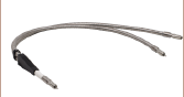
Custom Ruggedized MIR Patch Cable


Please Wait
Click Below for In-Stock MIR Products


Click to Enlarge
Click for Raw Data
ZrF4 fiber has flatter attenuation than InF3 fiber in the MIR, while the InF3 fiber is transparent to longer wavelengths. Silica fiber, typically used in patch cables, is not MIR-transparent. For information on run-to-run variations, please see the Graphs tab.
Custom MIR Fiber and Patch Cables
If our standard offerings do not meet your needs, please contact Tech Support to discuss customization and potential fiber draws. Some of the many customization options we provide for MIR fibers and patch cables include:
- Hand Selected Extra-Low-Loss MIR Fibers to Meet
Strict Attenuation Requirements - Custom Core and Cladding Geometries
- Dual-Polymer Claddings Available
- Increased Power Handling Capabilities
- Custom Options: Fiber Type, Length, Termination,
and Tubing - OEM Patch Cables: Designed for Application Requirements
- AR-Coated Patch Cables
- Ruggedized Cabling for Harsh Environments
Features
- ZBLAN Zirconium Fluoride (ZrF4) Fibers with Transmission from 285 nm to 4.5 µm
- Indium Fluoride (InF3) Fibers with Transmission from 310 nm to 5.5 µm
- Multimode Fiber and Patch Cable Options
- Core Size: Ø100 to Ø600 µm
- Numerical Aperture: 0.20 or 0.26
- Single Mode MIR Fiber and Patch Cable Options:
- ZrF4: 2.3 - 4.1 µm SM Operating Range
- InF3: 3.2 - 5.5 µm SM Operating Range
- Fiber Bundles and Reflection/Backscatter Probes Available
- Flexible Manufacturing Processes for Catalog and Custom Products (See MIR Manufacturing Tab for Details)
Applications
- Spectroscopy
- Fiber Lasers
- Supercontinuum Light Sources
- Environmental Monitoring
- Medical Diagnostics
- Chemical Sensing
- IR Imaging
Thorlabs manufactures an extensive family of mid-infrared fiber and fiber patch cable products; fibers with many other core sizes and configurations are currently under development. Products available from stock with same-day shipping include single mode and multimode patch cables, as well as bifurcated fiber bundles for transmission applications and reflection/backscatter probes designed for spectroscopy. Specifications for the fibers used in these products are included in the table below. Bare MIR fiber can be requested by contacting Tech Support.
Our IRphotonics® MIR fibers and patch cables, based upon ZBLAN zirconium fluoride (ZrF4) and indium fluoride (InF3) glasses, feature excellent mechanical flexibility, good environmental stability, and high transmission over the 285 nm - 4.5 µm spectral range or 310 nm - 5.5 µm spectral range, respectively. Like the rest of our fiber selection, fluoride fibers can be provided in a range of core diameters, cutoff wavelengths, and numerical apertures, suiting a variety of applications (see the tables below for fiber specifications).
Thorlabs' fluoride fibers are manufactured using a proprietary technique that provides world-class purity, dimensional control, and strength. This technique gives us excellent control over the fibers' optical and mechanical properties, allowing a wide range of configurations to be drawn (see the MIR Manufacturing Tab for more information). Fluoride fibers offer a flat attenuation curve in the MIR wavelength range (see the Graphs tab), aided by an extremely low hydroxyl ion (OH) content. The refractive index of fluoride glass is near that of silica; therefore, optical fibers manufactured using fluoride glass exhibit lower return loss and low Fresnel reflections compared to chalcogenide glass fibers.
| Fiber Type | Operating Wavelengtha |
Core Diameter |
Attenuationb | NA | Long-Term Bend Radius |
Short-Term Bend Radius |
Cladding Diameter |
Coating Diameter |
Operating Temperature |
|---|---|---|---|---|---|---|---|---|---|
| ZrF4 (ZBLAN) |
285 nm - 4.5 µm | 100 ± 2 µmc | ≤0.2 dB/m (from 2.0 - 3.6 µm) |
0.20 ± 0.02 @ 2.0 µm |
≥155 mm | ≥25 mm | 192 ± 2.5 µm | 270 ± 15 µm | -55 to 90 °C |
| 200 ± 10 µmc,d | ≥80 mm | ≥40 mm | 290 ± 10 µm | 355 ± 15 µm | |||||
| 450 ± 15 µmc,e | ≥125 mm | ≥30 mm | 540 ± 15 µm | 650 ± 25 µm | |||||
| 600 ± 20 µmc,e | ≤0.25 dB/m (from 2.0 - 3.6 µm) |
≥160 mm | ≥75 mm | 690 ± 20 µm | 770 ± 30 µm | ||||
| InF3 | 310 nm - 5.5 µm | 100 ± 2 µmc | ≤0.45 dB/m (from 2.0 - 4.6 µm) |
0.26 ± 0.02 @ 2.0 µm |
≥155 mm | ≥15 mm | 192 ± 2.5 µm | 287 ± 15 µm | -55 to 90 °C |
| 200 ± 10.0 µmc | ≤0.3 dB/m (for 2.0 - 4.6 µm) |
≥200 mm | ≥40 mm | 290 ± 10.0 µm | 430 ± 25 µm |
| Fiber Type | Transmission Range |
SM Operating Wavelength |
Core Diametera | Attenuation | NA | Long-Term Bend Radius |
Short-Term Bend Radiusb |
Operating Temperature |
|---|---|---|---|---|---|---|---|---|
| ZrF4 (ZBLAN) |
285 nm - 4.5 µm | 2.3 - 4.1 µm | 9 ± 0.5 µm | <0.2 dB/m (from 2.3 - 3.6 µm) |
0.19 ± 0.02 @ 2 µm |
≥30 mm | ≥10 mm | -55 to 90 °C |
| InF3 | 310 nm - 5.5 µm | 3.2 - 5.5 µm | 9 ± 0.5 µm | <0.45 dB/m (from 3.2 - 4.6 µm) |
0.26 ± 0.02 @ 2 µm |
≥30 mm | ≥10 mm | -55 to 90 °C |
Multimode Fluoride Patch Cables Attenuation

Click to Enlarge
Click for Raw Data
This plot contains the measured attenuation from five independent draws of the Ø200 µm core ZrF4 fiber. This data is representative of our Ø100 µm, Ø200 µm, and Ø450 µm core fibers.

Click to Enlarge
Click for Raw Data
This plot contains the measured attenuation from five independent draws of the Ø600 µm core ZrF4 fiber.

Click to Enlarge
Click for Raw Data
This plot contains the measured attenuation from six independent draws of the Ø100 µm core InF3 fiber.

Click to Enlarge
Click for Raw Data
This plot contains the measured attenuation from five independent draws of the Ø200 µm core InF3 fiber.
Single Mode Fluoride Patch Cables Attenuation

Click to Enlarge
Click for Raw Data
This plot contains the measured attenuation for our single mode ZrF4 fiber. The green shaded region in the plot denotes the specified range for single mode operation with attenuation ≤0.3 dB/m, and the blue shaded region denotes the range for single mode operation without a guaranteed attenuation specification. The orange shaded region denotes the range where the fiber is still transmissive, but provides multimode operation.The cutoff wavelength, denoted by a dashed vertical line, is the onset of this multimode operation and will vary from run to run. The peak near 1.9 µm corresponds to attenuation of the second-order mode.

Click to Enlarge
Click for Raw Data
This plot contains the measured attenuation for our single mode InF3 fiber. The green shaded region in the plot denotes the specified range for single mode operation with attenuation ≤0.45 dB/m, and the blue shaded region denotes the range for single mode operation without a guaranteed attenuation specification. The orange shaded region denotes the range where the fiber is still transmissive, but provides multimode operation. The cutoff wavelength, denoted by a dashed vertical line, is the onset of this multimode operation and will vary from run to run. The peak near 2.9 µm corresponds to attenuation of the second-order mode.

Click to Enlarge
Click for Raw Data
This plot contains the measured attenuation for a single loop of our single mode ZrF4 fiber at five different bend radii. The blue and green shaded regions in the plot together denote the single mode wavelength range (2.3 - 4.1 µm).

Click to Enlarge
Click for Raw Data
This plot contains the measured attenuation for a single loop of our single mode InF3 fiber at four different bend radii. The blue and green shaded regions in the plot together denote the single mode wavelength range (3.2 - 5.5 µm).
Testing and Characterization Capabilities
- Spectral Attenuation Measurement
- UV / Visible / NIR / MIR Wavelength Range
- SM or MM Fiber and Bulk Glass
- SM Fiber Cutoff Wavelength Measurement
- Fiber NA Measurement
- Fiber Glass / Coating Geometry Measurement with Sub-µm Accuracy
- MIR High-Power Screening for MM Fibers
- Fiber Tensile Strength Testing
- Defect / Break Analysis
- Degree of Cure Testing for Fiber Coatings
Request testing for Thorlabs or third-party fibers by contacting Tech Support.
Capabilities
- ZBLAN Zirconium Fluoride (ZrF4) and Indium Fluoride (InF3) Fiber Production
- Design and Manufacturing Provide Low-Loss MIR Transmission up to 5.5 µm
- Flexible Manufacturing Setups and Schedules Accommodate Prototyping as well as Catalog Production
Thorlabs' optical fiber draw facility produces ZBLAN zirconium fluoride (ZrF4) and indium fluoride (InF3) fibers in addition to silica fiber. ZrF4 and InF3 fibers feature high transmission over the 300 nm - 4.5 µm and 300 nm - 5.5 µm spectral ranges, respectively. Key fiber properties include no material absorption peaks, excellent mechanical strength, and good environmental stability.
Fluoride fibers are ideal for transmission in the MIR wavelength range, and Thorlabs' fibers feature low attenuation over this range as a result of stringent manufacturing processes yielding an extremely low hydroxyl ion (OH) content. Fluoride fibers also have a lower refractive index and lower chromatic dispersion when compared to other fibers that offer transmission in the MIR range, such as chalcogenide glass fibers. Thorlabs' fluoride fibers are ideal for use in applications including MIR spectroscopy, fiber optic sensors, imaging, and fiber lasers.
Fluoride Preform Manufacturing and Fiber Draw Process
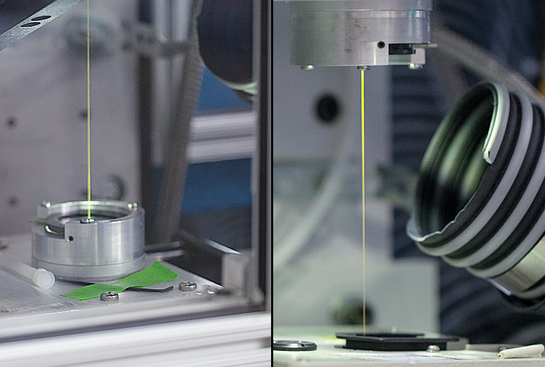
Thorlabs' fluoride fibers are fabricated using a technique that provides world-class purity, dimensional control, and strength. The glass components are combined and melted in the controlled environment of a glove box for purity. Once the glass is melted, it is poured into the preform mold and cooled.
After preparation, the preform is loaded into the down-feed unit at the top of the tower and drawn into fiber. Fluoride glass fiber is drawn using preform techniques similar to that used for silica fibers. This technique is well developed and has proven to be very effective in controlling fiber parameters, such as fiber diameter, concentricity, and the refractive index profile. The drawing temperature range of fluoride glasses is lower than that of silica, significantly reducing the cooling time. Thus, our fluoride fiber draw tower is much shorter than our silica fiber towers. The diagram below to the right details the components on our fluoride fiber draw tower.
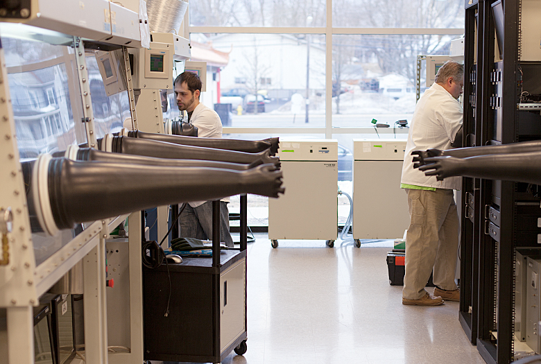
Thorlabs' team of MIR fiber researchers and engineers has many years of experience in fluoride glass research and development, production, and fiber draw. Our team is divided into two groups: one dedicated to production of catalog items and the second devoted to research and development and custom fiber manufacturing. Their knowledge and expertise, as well as flexible tower configurations and draw schedules, allow us to produce both catalog items as well as custom orders. For details on our custom fluoride fiber capabilities, please contact Tech Support.
Fluoride Fiber Characterization and Testing
Thorlabs has a team dedicated to the testing and characterization of our fiber products. We precisely measure the properties of each drawn fiber to ensure that it meets our high standards of quality. Extensive testing also provides feedback for our fiber draw team, enabling tight control of each step in the manufacturing process. Customers can request custom testing of any Thorlabs-manufactured fiber, which is then provided with the shipped fiber. Testing of third-party fiber samples provided by customers is also available upon request. Available tests and services are provided in the list to the right; please contact Tech Support with inquiries.

Schematic of Our MIR Fiber Draw Tower
Thorlabs' MIR Fiber Capabilities


Thorlabs Lab Facts: Modifying Beam Profiles with Multimode Fibers
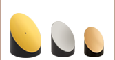
We present laboratory measurements demonstrating how the output beam profile from multimode fiber can be affected by the beam entry angle. In some applications, an alternative beam distribution such as a top hat or donut is desired instead of the inherent Gaussian distribution provided by typical optics. Here we investigated the effect of changing the input angle of a focused laser beam into a multimode fiber patch cable. Focusing the light normal to the fiber face produced a near-Gaussian output beam profile (Figure 1) and increasing the angle resulted in top hat- (Figure 2) and donut-shaped (Figure 3) beam profiles. These results demonstrate how multimode fibers can be used to change the shape of a beam profile.
For our experiment, we used an M38L01 Ø200 µm, 0.39 NA, Step-Index Fiber Patch Cable (Bare Fiber Item # FT200EMT) as the test fiber into which we launched the focused laser beam. The input light was set incident at 0°, 11°, and 15° to the input face of the multimode fiber to create the initial, top hat, and donut profiles, respectively. Each time the angle was changed, the alignment of the input fiber was optimized while the output power was monitored with a power meter to ensure maximum coupling was achieved. Images were then acquired with a 9 second exposure and the shape of the beam profile was evaluated. Note that during the exposure, a 1500 grit diffuser was manually rotated between the coupling optics (before the fiber under test) to reduce the spatial coherence and create a clean output beam profile.

Assuming a ray tracing model, there are two general types of rays that propagate along a multimode fiber: (a) meridional rays, which pass through the central axis of the fiber after each reflection, and (b) skew rays, which never pass through the central axis of the fiber. The figures below illustrate the three basic ray propagation scenarios observed during the experiment. Figures 4 and 6 depict meridional and skew ray propagation through multimode fiber, respectively, and the associated theoretical beam distribution at the fiber output. As illustrated in Figure 6, skew rays propagate in a helical path along the fiber that is tangent to the inner caustic of the path with radius r. Figure 5 depicts the beam propagation and beam distribution from a combination of meridional and skew rays. By changing the input angle of the light launched into a multimode fiber, we were able to modify the proportion of light rays propagating as meridional rays vs. skew rays, and consequently, modify the output from a near-Gaussian distribution (primarily meridional rays, see Figure 1) to a top hat (mixture of meridional and skew rays, see Figure 2) to a donut (primarily skew rays, see Figure 3). The beam profiles shown in Figures 4 through 6 were obtained at a distance of 5 mm from the fiber end face. These results demonstrate the ability to use a standard multimode fiber patch cable as a relatively inexpensive method to modify an input Gaussian profile into a top hat and donut profile with minimal loss. For details on the experimental setup employed and these summarized results, please click here.

Figure 1. Near-Gaussian Beam Profile
Obtained at 0° Input Angle (Normal to Fiber Face)

Figure 3. Donut Beam Profile
Obtained at 15° Input Angle

Figure 2. Top Hat Beam Profile
Obtained at 11° Input Angle


| Posted Comments: | |
Jun Zhao
(posted 2020-07-28 17:15:42.74) Could you suggest and quote for InF3 fiber with core size of 10um? nbayconich
(posted 2020-07-28 11:15:23.0) Thank you for contacting Thorlabs, I will reach out to you directly to discuss our custom capabilities. Ian McLaughlin
(posted 2019-08-28 14:40:21.59) Please provide a quote for the Mid-Infrared Optical Fiber nbayconich
(posted 2019-08-28 04:18:38.0) Thank you for contacting Thorlabs. I will reach out to you directly to discuss our custom capabilities and quote you a custom patch cable.
For future custom requests please contact techsupport@thorlabs.com directly or you can request a quote from the "Request Quote" link above the feedback section. todd
(posted 2017-03-03 11:36:46.65) What is the fluoride fiber buffer material? Is the buffer strippable? Once I know this I will figure out how much fiber I will need a quote for. tfrisch
(posted 2017-03-13 02:41:45.0) Hello, thank you for contacting Thorlabs. The buffer is acrylate, and I will contact you directly on how the recommended handling differs from silica fibers. ilindsay
(posted 2015-08-27 15:41:39.307) Hi.
Can you comment on the end preparation of your mid-IR (fluoride) fibers, e.g. differences from SiO2 fibers in terms of cleaving and polishing techniques in the case of applications where connectors are not appropriate? besembeson
(posted 2015-09-29 08:59:55.0) Response from Bweh at Thorlabs USA: We recommend Thorlabs Vytran products, such as the LDC-400 (http://vytran.com/product/ldc-400) for cleaving bare fiber. Polishing is only relevant when terminating fiber with a connector and it is different with these mid-IR fibers. I will follow-up with you for further guidance with these if needed. |