 Products Home / Optical Power and Energy Meters / Optical Power and Energy Meter, Dual-Channel Benchtop Console
Optical Power and Energy Meter, Dual-Channel Benchtop Console

- Power and Energy Measurements for Free Space and Fiber
- Large 240 x 128 Pixel Graphics Display, USB 2.0 Interface
- Wide Array of Mathematical Functions
- Compatible with Over 25 Sensors
PM320E
Benchtop
Photodiode, Fiber, Integrating
Sphere, Thermal, and Pyroelectric
Sensors Available
Detector Options


Please Wait
| Item # | PM320E |
|---|---|
| Compatible Sensors | Photodiode, Thermal, and Pyroelectric |
| Number of Channels | 2 |
| Optical Power Rangea | 100 pW to 200 W |
| Optical Energy Rangea | 10 µJ to 15 J |
| Available Sensor Wavelength Rangea | 185 nm - 25 μm |
| Display Refresh Rate | 20 Hz |
| Bandwidtha | DC - 100 kHz |
| Photodiode Sensor Rangeb | 100 nA - 10 mA |
| Thermopile Sensor Rangeb | 1 mV - 1 V |
| Pyroelectric Sensor Rangeb | 100 mV - 100 V |
| Power Meter Selection Guide |
|---|
| Sensors |
| Photodiode Power Sensors |
| Thermal Power Sensors |
| Thermal Position & Power Sensors |
| Pyroelectric Energy Sensors |
| Power Meter Consoles |
| Digital Handheld Console |
| Analog Handheld Console |
| Touchscreen Handheld Console |
| Dual-Channel Benchtop Console |
| Complete Power Meters |
| Power Meter Bundles |
| Wireless Power Meters with Sensors |
| Compact USB Power Meters |
| Field Power Meters for Terminated Fibers |
| USB Interfaces, External Readout |
Features
- Dual-Channel Power and Energy Meter Benchtop Console
- Over 25 Compatible Sensors
- Large Graphics Display
- Advanced Display and Measurement Features
- Programmable Channels: Monitor, Difference, Ratio, Math Functions, Linear and Log Values, Attenuation
- USB 2.0 Interface and Software Suite
- Continuous and Single-Shot Energy Measurement of Pulsed Laser Sources
Thorlabs’ Dual Channel PM320E Power and Energy Meter offers many feaures not found in handheld devices. It is ideal for precise optical measurements, laser and photodiode characterization, lifecycle measurements and many more applications in the lab and on the manufacturing floor.
The dual-channel design enables differential and ratiometric measurements. Intuitive manual operation with the large graphics display, compatibility with conventional photodiodes, and excellent remote capabilities enable easy system integration.
The PM320E is compatible with all Thorlabs Photodiode Sensors, Thermal Sensors, and Pyroelectric Sensors. It also allows the connection of unamplified anode or cathode grounded photodiodes with up to 10 mA photocurrent, thermal elements with up to 1 V output voltage, and pyroelectric detectors with up to 100 V output voltage.
Additionally the PM320E offers energy measurements with all Thorlabs Pyroelectric Energy Sensors (both channels). More information can be found in the Sensor Selection tab. The PM320E is sold as a single benchtop device with the sensors available separately. The compatible sensors are listed below.
Console Design
The calibrated sensors connect via two sub-D connectors on the rear panel, which also provides two analog high bandwidth outputs to allow monitoring of each channel, plus the programmable analog output. Optical sources may be attenuated / gained electronically through the console (Note: Attenuating the source through the console will not attenuate the light at the detector and damage may still occur above the detector threshold power.) Optional user-supplied photodiodes connect via two BNC inputs on the front panel, which feature switchable bandwidth and a programmable bias voltage. The input can be switched between the front and rear connectors. The additional BNC output is gain-and-function programmable. It provides an analog voltage proportional to the output of one of the channels or as a difference or ratio of the two power meter channels. The measurement resolution is 16 bit for all power ranges. The PM320E is controlled locally via the front panel, which features a large 240 x 128 pixel LCD display, or remotely via USB 2.0.
In addition to the console, the following comes with each purchase: Software CD ROM, LabVIEW™ and LabWINDOWS™ /CVI Driver Set, Certificate of Calibration, and Operation Manual.
To view the full range of Thorlabs' power and energy meter consoles, please refer to the Console Selection tab.
Sensor Upgrade Service
Thorlabs' Sensors and PM320E Console are not compatible with old power meter consoles and sensor heads, respectively. We offer a sensor upgrade service if you want to use your existing sensors with a new power meter console. Note: upgraded sensors will be incompatible with old power meter consoles and new sensors converted to work with older consoles will not be compatible with the PM320E. Please contact our Tech Support team for details.
Recalibration Service
Recalibration services are available for our thermal and photodiode power sensors, pyroelectric energy sensors, and consoles. We recommend recalibrating your Thorlabs sensor and console as a pair; however, each may be recalibrated individually. The console recalibration is offered at a discount when recalibrated with a sensor. To order a recalibration service that includes the PM320E, please contact Tech Support.
| Item # | PM320E |
|---|---|
| Display | |
| Display Type | Graphical LCD 240 x 128 pixels |
| Display Screens | Numerical, Bargraph, Linegraph, Statistics, Simulated Analog Needle |
| Viewing Area | 3.7" x 2.4" |
| Refresh Rate | 20 Hz |
| Sensor Interface | |
| Compatible Sensors | All Photodiodes, Thermopiles, and Pyros See below for full sensor specs |
| Channels | 2 |
| Input Connection | 2x DB9, Rear 2x BNC, Front |
| Trigger Connection | BNC, Rear |
| Analog Outputs | |
| Connector | 2x BNC, Rear |
| Signal | Ch1, Ch2 Amplified Input Signal |
| Voltage Range | 0 to ±10 V |
| Bandwidth | Up to 100 kHz, Dependent on Sensor and Settings |
| Programmable Analog Output | |
| Connector | BNC, Rear |
| Signal | Selectable: Ch1, Ch2, Ch1-Ch2, Ch1/Ch2 |
| Voltage Range | 0 to ±10 V |
| Bandwidth | up to 500 Hz, Dependent on Sensor and Settings |
| Digital Outputs | |
| Connector / Interface | USB, Rear / USB 2.0 |
| Power Supply | |
| Line Voltage | 100 / 115 / 230 V (-10%, +10%) |
| Line Frequency | 50 to 60 Hz |
| Dimensions and Mounting | |
| Dimensions (L x W x H) | 220 mm x 122 mm x 325 mm |
| Weight | <4 kg |
| Mounting Options | Benchtop |
| Operating Temperature | 0 to 40 °C |
| Storage Temperature | -40 to 70 °C |
Sensor Compatibility Specs
| Item # | PM320E | ||
|---|---|---|---|
| Detector Compatibility | Photodiode Sensors: S1xxC Series Photodiodes (Max 10 mA)a |
Thermal Sensors: S3xxC Series Thermopiles (Max 100 mV) |
Pyroelectric Sensors: ESxxxC Series Pyros (Max 100V) |
| Input | Ch1, Ch2 / DB9, Rear / BNC, Front | Ch1, Ch2 / DB9, Rear | Ch1, Ch2 / DB9, Rear |
| Measurement Ranges | 6 Decades; 100 nA - 10 mA Ranges Selectable in W, Sensor Dependent |
4 Decades; 1 mV - 1 V Ranges Selectable in W, Sensor Dependent |
4 Decades; 100 mV - 100 V Ranges Selectable in J, Sensor Dependent |
| Wavelength Ranges | 200 nm - 1800 nm | 190 nm - 25 μm | 185 nm - 25 μm |
| Power / Energy Ranges | 100 pW - 20 W | 100 μW - 200 W | 10 μJ - 15 J |
| Units | W, dBm, W/cm², A (Photodiodes only) | W, dBm, W/cm² | J, J/cm², W, W/cm² |
| Accuracy | ±0.2% of Full Scale (1 µA - 10 mA) ±0.5% of Full Scale (100 nA) |
±0.5% of Full Scale | ±0.5% of Full Scale |
| Display Resolution | 10 pA / Responsivity Value (A/W) | 1 µV / Responsivity Value (V/W) | 100 µV / Responsivity Value (V/W) |
| Bandwidth | DC - 100 kHz, Dependent on Sensor and Settings | DC - 10 Hz, Dependent on Sensor and Settings | 3 kHz (Max. Rep. Rate) |
| Wavelength Correction | Sensor Dependent; nm (A/W) | Sensor Dependent; nm (V/W) | Sensor Dependent; nm (V/J) |
For a full list of the sensor head specifications please visit the Photodiode Power Sensors, Thermal Power Sensors, or Pyroelectric Energy Sensors pages. For other information, please contact Tech Support.
| Pin | Connection | Pin | Connection |
|---|---|---|---|
| 1 | +5 V (Drive Max. 50 mA from this Pin) | 5 | Pyro-Electric Sensor + |
| 2 | EEPROM Digital I/O | 6 | DGND |
| 3 | Photodiode Ground (Anode), Thermal and Pyro Sensor Ground | 7 | PRESENT Connect this Pin via a 1 - 10 kΩ Resistor to Pin 3 (AGND) |
| 8 | Thermal Sensor + | ||
| 4 | Photodiode Cathode | 9 | Not Connected |
Sensor Connector
D-type Female

Photodiode Input
BNC Female

Analog Output
BNC Female
0 ... ± 10 V, Min Load 10 kΩ
Chassis Ground
4 mm Banana Jack

Trigger Input
BNC Female
TTL, Max Frequency 1.5 kHz
Programmable Analog Output
BNC Female
0 ... ± 10 V, Min Load 10 kΩ
Computer Connection
USB Type B

USB Type B to Type A Cable Included
Standard Photodiode Sensor Mounting Options


Thorlabs Standard Photosdiode Sensors compact design allows easy integration into existing setups. Typical mounting configurations including post, cage, and lens tube options are available. Shown on this page are several different choices for mounting these sensors.
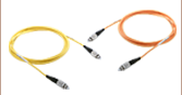
The Standard Photodiode Sensors are compatible with all S120-xx Series fiber adapters. FC/PC and SMA adapters are shown on the right. Adapters for FC/APC, SC, LC, and ST connections are also available.


Flip up mounts are convenient for quick power measurments from a static location. The sensor can be placed in the path of the laser beam for the power measurment and flipped down during normal operation of the system.
FM90 Right Angle Flip-Mounts are shown to the right. Thorlabs also offers the TRB1 Articulating Post Mount. The lockable articulating mount offers almost unlimited positioning of the sensor head. The articulating mount is shown on an S13xC Slim Photodiode Sensor below.


The Standard Photodiode Sensors also feature SM1 threaded connections on the front face. The SM1 theading provides easy mounting to 1" lens tube systems and quick release mounts.
Shown to the right are the KB1P Quick-Release Post Mount and QRC1A Quick-Release 30 mm Cage Mount. Both mounts feature SM1 threaded connections to the sensor heads.
Note: Due to the thickness of the S12xC sensor, the QRC1A and CP44F (shown below) quick release mounts can only be fully removed from the cage system by backing them off an open end. The two mounts are easily removed from the cage system if only three cage mounts are used. See the picture on the right.
Thorlabs also offers the CP44F 30 mm Cage Plates with Quick-Release Mounts. These mounts feature magnetically coupled mounting for easy and repeatable mounting.
Note: Like the QRC1A, the CP44F can not be removed from a closed cage system.
Slim Photodiode Sensor Mounting Options

Thorlabs' Slim Photodiode Sensors are designed to fit into tight optic arrangements such as cages, lens tubs, and optic dense free space arrangements.
Shown to the right is a S130C Sensor inserted into a 30 mm cage system. The application shown highlights the ease for which the sensor can be inserted into the cage, and the minimal space needed to take a power measurment.
The Slim Photodiode Sensors may also be mounted on a TRB1 Articulating Mount. This mount allows repeatable insertion of the sensor into tight optic arrangements. After the measurement is made, the sensor may be rotated out of the beam path for normal operation.
Microscope Slide Photodiode Sensor Mounting Options

S170C Mounted on a Post
The S170C may be post mounted via the 8-32 (M4) tap in the side of the housing.

The S170C microscope slide power Sensor is designed so that it can be mounted directly in a microscope slide holder. The 76.0 mm x 25.2 x 5.0 mm sensor head has the same footprint as a standard microscope slide and is compatible with most standard upright and inverted microscopes. The photo to the right shows the power sensor flipped over so that the engraved back of the housing can be used for alignment.
This power sensor also has an 8-32 (M4) tap for post mounting. In the photo to the far right, an RA90 is used with two Ø1/2" posts to mount the sensor head in a horizontal orientation.
Integrating Sphere Photodiode Sensor Mounting Options

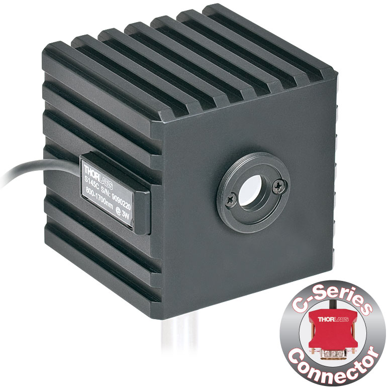
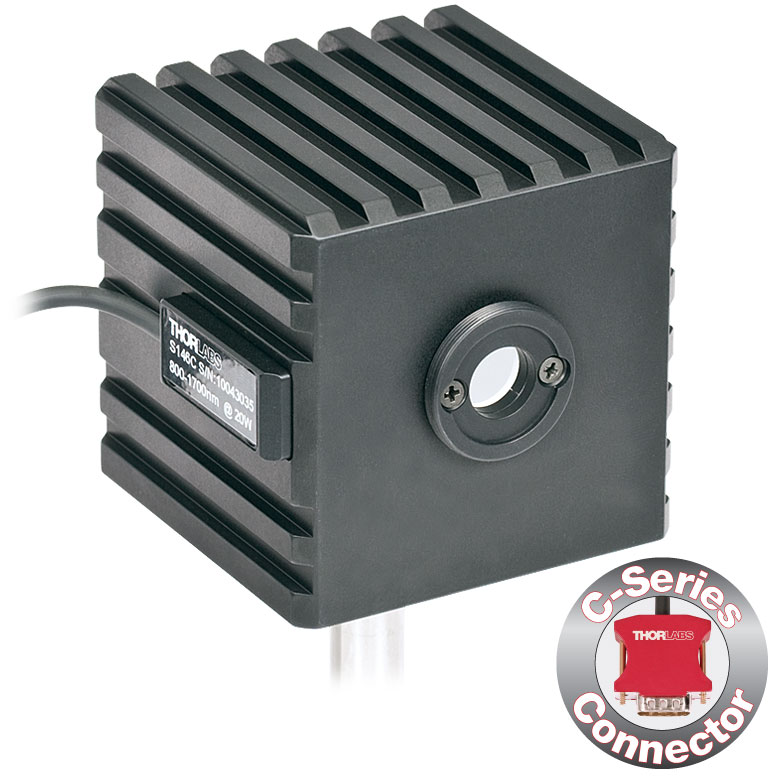
Thorlabs' Integrating Sphere Photodiode Sensor provides a low loss cavity for diverging, non-uniform, or off-axis beam measurements. These integrating spheres are ideal for all fiber based applications due to the beam divergence at the end of the fiber.
Shown to the right is an S140C Integrating Sphere with S120-FC Fiber Adapter. Also shown is an S140C with a S140-BFA Bare Fiber Adapter. The Bare Fiber adapter features a mounting clamp and light shield to decrease interference from ambient light.
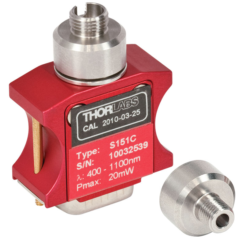
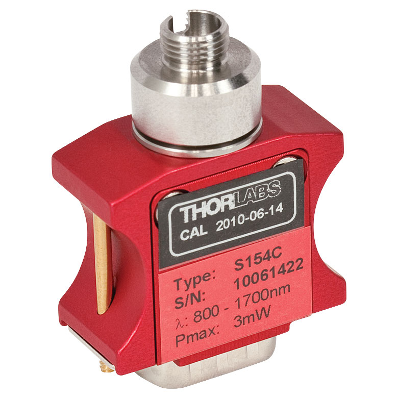
Compact Fiber Photodiode Sensor Mounting Options

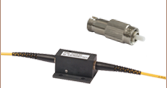
Thorlabs' Compact Fiber Photodiodes are the ideal choice for a portable, fiber coupled power meter. The S15xC sensors are compatible with a wide variety of fiber connections. PM20-xx adapters are available to couple FC, APC, SMA, ST, SC, and LC connectors with the sensors. Shown to the right is a S150C Sensor with FC and SMA connector adapters.
Shown to the far right is a PM100D console with S150C sensor connected to a FC connectorized optical fiber. This setup is ideal for portable in the lab and in the field use.
Pyroelectric Energy Sensor Mounting Options

Thorlabs' Pyroelectric Energy Sensors are ideal for measuring pulsed sources. These pyroelectric sensors provide direct energy readings for those sources. The sensors are designed to handle medium to high energy pulses from Excimer, YAG, and other high power lasers.
Mounting options include post (with insulating adapter) and cage configurations, shown to the right.
Software for the PM320E
This series is provided with a software package including drivers for LabVIEW™ and LabWindows™. This software is compatible with Windows® XP, Vista, 7, 8, or 10.
Software
Version 1.0
Remote data logging software for the PM320E Dual Channel Optical Power and Energy Meter. This package includes the most up-to-date drivers.

Click to Enlarge
The PM160 wireless power meter, shown here with an iPad mini (not included), can be remotely operated using Apple mobile devices.
This tab outlines the full selection of Thorlabs' power and energy sensors. Refer to the lower right table for power meter console and interface compatibility information.
In addition to the power and energy sensors listed below, Thorlabs also offers all-in-one, wireless, handheld power meters and compact USB power meter interfaces that contain either a photodiode or a thermal sensor, as well as power meter bundles that include a console, sensor head, and post mounting accessories.
Thorlabs offers four types of sensors:
- Photodiode Sensors: These sensors are designed for power measurements of monochromatic or near-monochromatic sources, as they have a wavelength dependent responsivity. These sensors deliver a current that depends on the input optical power and the wavelength. The current is fed into a transimpedance amplifier, which outputs a voltage proportional to the input current.
- Thermal Sensors: Constructed from material with a relatively flat response function across a wide range of wavelengths, these thermopile sensors are suitable for power measurements of broadband sources such as LEDs and SLDs. Thermal sensors deliver a voltage proportional to the input optical power.
- Thermal Position & Power Sensors: These sensors incorporate four thermopiles arranged as quadrants of a square. By comparing the voltage output from each quadrant, the unit calculates the beam's position.
- Pyroelectric Energy Sensors: Our pyroelectric sensors produce an output voltage through the pyroelectric effect and are suitable for measuring pulsed sources, with a repetition rate limited by the time constant of the detector. These sensors will output a peak voltage proportional to the incident pulse energy.
| Console Compatibility | |||||||
|---|---|---|---|---|---|---|---|
| Console Item # | PM100A | PM100D | PM400 | PM320E | PM101 Series |
PM102 Series |
PM100USB |
| Photodiode Power |  |
|
|
|
|
- | |
| Thermal Power | |
|
|
|
|
|
|
| Thermal Position | - | - | |
- | - | |
- |
| Pyroelectric Energy | - | |
|
|
- | - | |
Power and Energy Sensor Selection Guide
There are two options for comparing the specifications of our Power and Energy Sensors. The expandable table below sorts our sensors by type (e.g., photodiode, thermal, or pyroelectric) and provides key specifications.
Alternatively, the selection guide graphic further below arranges our entire selection of photodiode and thermal power sensors by wavelength (left) or optical power range (right). Each box contains the item # and specified range of the sensor. These graphs allow for easy identification of the sensor heads available for a specific wavelength or power range.
| Photodiode Power Sensors |
|---|


| Thermal Power Sensors |
|---|


| Thermal Position & Power Sensors |
|---|


| Pyroelectric Energy Sensors |
|---|


Sensor Options
(Arranged by Wavelength Range)

Sensor Options
(Arranged by Power Range)


| Posted Comments: | |
Kazuya Takayama
(posted 2020-03-17 09:52:10.903) I have a qestion about the relative power measurement (3.1.5 in PM320E-Manual).
Let's say I measure two powers in dBm, such as 0.00 dBm(or in W) for Ch1 and -12.34 dBm(or in W) for Ch2. Then, I select relative power measurement, such as Ch1(W)/Ch2(W) dB or Ch1(dBm) - Ch2(dBm) dB. Do I see -12.340 dB in display with one digit higher resolution? My concern is how many display digit can be allowed for below decimal point.
Thank you for your kind suuport on this matter in advance.
Best Regards, MKiess
(posted 2020-03-19 07:49:38.0) This is a response from Michael at Thorlabs. Thank you very much for your feedback. The display itself can only show four numbers with our sensors. A higher accuracy is often not given by the calibration of sensors. The digits after the decimal point are determined by the selected power range.
If the relative power measurement mode is selected, the main display and the bar graph show the difference with a resolution of one digit higher than the displayed, subtracted value. Alan Blair
(posted 2020-01-03 16:47:17.357) I have two issues with the PM320E.
1. The driver will not install under windows 10. I get an error stating that the driver does not have a valid digital signature.
2. I'd like to control the PM320E using C#, do you have an example in any .NET language for this meter? MKiess
(posted 2020-01-07 07:58:27.0) This is a response from Michael at Thorlabs. Thank you very much for your feedback. We have immediately added the ability to search for devices and read the resource string passed to the Init function to the existing driver for PM320E. The driver thus meets our current standard for VXIpnp drivers and works under Windows10. I have sent you the new installation package, which is now also available for download on our website, directly. anays.acevedo
(posted 2019-02-22 02:11:17.07) When I try to uninstall the utility software, it prompt an error 1721. How can I sove it? nreusch
(posted 2019-02-28 08:54:54.0) This is a response from Nicola at Thorlabs. Thank you for reporting this error. I will contact you directly for further troubleshooting. jon.peterson
(posted 2018-09-19 16:45:27.323) Do you have a document which describes the USB interface? I would prefer to write my own software to automate the PM320E. nreusch
(posted 2018-09-24 06:06:52.0) This is a response from Nicola at Thorlabs. Thank you for your inquiry. In chapter 4 and 5 of the manual, you will find a general remote operation description as well as a command reference list. At https://www.thorlabs.com/software_pages/ViewSoftwarePage.cfm?Code=PM300 you can download the drivers that you might need to write your own application with e.g. Labview. I will contact you directly to check whether you need any further assistance. michael.mayers
(posted 2018-08-28 14:18:51.873) I need to know the AC input power consumption of the PM320E. swick
(posted 2018-09-12 04:12:08.0) This is a response from Sebastian at Thorlabs. Thank you for the inquiry.
The PM320E has maximum power consumption of 20 VA. michael.mayers
(posted 2018-08-21 09:55:00.17) Need to know if there are Labview drivers available for the PM320E? swick
(posted 2018-08-30 04:11:55.0) This is a response from Sebastian at Thorlabs. Thank you for the inquiry.
For PM320E the Labview drivers are included to the standard software installation and to the driver package, which you can download here:
https://www.thorlabs.com/software_pages/ViewSoftwarePage.cfm?Code=PM300 dmitry.busko
(posted 2017-07-03 12:01:30.7) Dear Thorlabs Team,
We have PM320E connected with S120C head. some questions:
1. with a room light on and without a signal the powermeter quite often clicking like a hell with a frequency 1-2 Hz. I think it just sweeping between two low ranges there and back, and can not decide where to stay... I can send a video of this behavior if needed.
2. We do intensity dependence measurement and it happens, that after changing the range (usually only for 1mW->10mW transition) powermeter shows the power approximately half less than actual. After several measurements with increasing intensity it jumps back to real power.
Are these problems known and solved (new firmware available) or - can one do something with it?! (not using autorange helps, but sometimes is not really convenient for not experienced users).
Regards,
Dmitry. swick
(posted 2017-07-04 04:18:24.0) This is a response from Sebastian at Thorlabs. Thank you for the inquiry.
I will contact you directly for troubleshooting. carsten.stock
(posted 2017-05-30 13:05:43.3) Hello, I am trying to use the Thorlabs PM320E with Labview (actual Labview2010, later i will switch to 2016) and can't find any examples (like "Roberto.narro" and "piotr.pytkowski"). Please can you provide an example for my LabView Versions? Many thanks in advance. swick
(posted 2017-06-01 03:57:37.0) This is a response from Sebastian at Thorlabs. Thank you for the inquiry.
I will contact you directly to provide requested example and for further assistance. llewins
(posted 2016-10-26 06:47:11.69) Hello, can you provide an example code, or tell me where to find one, of how to use this power meter with Labview using VISA comms or otherwise? wskopalik
(posted 2016-10-27 04:45:21.0) This is a response from Wolfgang at Thorlabs. Thank you for your inquiry.
There are example codes for LabView which either use the driver files or the SCPI commands described in the manual. They are normally installed by the installation routine. I will contact you directly and send you these files in case there has been any issue with the installation. nakeeran
(posted 2016-05-16 12:37:45.467) What is the InGaAs Photodiode (FGA10?) used with the power sensor S144C or S144A? shallwig
(posted 2016-05-17 05:24:26.0) This is a response from Stefan at Thorlabs. Thank you for your inquiry. The InGaAs photodiode build in the S144C and S144A has the part number FGA21, further specifications can be found in the spec sheet on our website here:
http://www.thorlabs.de/thorcat/13800/FGA21-SpecSheet.pdf roberto.narro
(posted 2014-12-03 19:05:31.197) Hello, I have the same problema that piotr.pytkowski. I am trying to use ThorLabs PM320E with LabView. I can't find any examples, and Initialize.VI doesn't contain instrument handle out. I am using NI Labview 2013 (32 bits). I would be grateful for any help. shallwig
(posted 2014-12-04 04:03:26.0) This is a response from Stefan at Thorlabs. Thank you very much for your inquiry. I will contact you directly to provide you an example for your Labview version. piotr.pytkowski
(posted 2014-04-15 07:09:59.783) Hello, I am trying to use ThorLabs PM320E with LabView. I can't find any examples, and Initialize.VI doesn't contain instrument handle out. I would be grateful for any help. shallwig
(posted 2014-04-16 04:45:18.0) This is a response from Stefan at Thorlabs. Thank you very much for your inquiry. Unfortunately, there is a LabView compatibility issue with this device. Therefore we have to check which exact LabView version you have and then we will send you an example. I will contact you directly. jvigroux
(posted 2012-10-08 13:09:00.0) a response form Julien at Thorlabs: Thank you for your inquiry! The PM320E can be in principle used with any thermopile detector or photodiode. The only physical limitation are the voltage and current readout ranges (100 nA - 10 mA and 1 mV - 1 V). The connector used are standard subD9 connectors. the detailed pin out of the connectors. For the use of custom Thermopile, it is further necessary to short pin 2 and 6 with a resistor of 10 to 15kOhms. You can find more detail about the exact procedure in the section 3.3.4 of the manual. tangt21
(posted 2012-10-08 06:38:22.0) Could Power Meter(PM320E) work for other detectors such as Newport's photodiode detector (918D-UV OD3) and thermopile detector (818P-070-12)?
Thanks you. Ed
(posted 2012-07-13 19:32:15.0) Does this PM320 powermeter have an audio feedback feature(ie acoustic pitch related to power level)? This is very usefull to 'hear' a light signal fluctuation, or adjust a photodiode to the max.
I am currently having difficulty coupling 633nm or 850nm single mode fibers rapidly just by looking at the bargraph. jvigroux
(posted 2012-01-11 10:18:00.0) a response from Julien at Thorlabs: thank you for your feedback! We will add this specification to our main specification table on the product page of those sensors. user
(posted 2012-01-10 16:15:42.0) It was very hard to find the "Max Average Power Density 100mW/cm² 10W/cm^2", eventually found it noted on the Spec Sheet, can i suggest you add this improtant specification to the main presentation. jvigroux
(posted 2011-11-16 08:13:00.0) a response from Julien at Thorlabs: Thank you for your feedback! this problem is indeed related to a Labview compatibility issue. I will send you a corrected version of the driver that solves this issue. We will also update the driver that is accessible online. cbrideau
(posted 2011-11-15 15:21:13.0) I'm using the PM300 with Labview but I can't get it to initialize. When the initialize window pops up it is empty. I see a previous poster had a similar problem. Is there an update of the initialize vi I could get? bdada
(posted 2011-09-15 20:28:00.0) Response from Buki at Thorlabs:
Thank you for your feedback. There is a .bas file installed with the driver for the PM300 series, and it can be found here: C:\Program Files\IVI Foundation\VISA\WinNT\include\PM300_Drv.bas
There is no example but normally, with this file, the programming and communicating in VB with the PM300 should be okay. zhongxiong.wu
(posted 2011-09-14 19:52:07.0) hi,we have bought an energy meter PM300E and we want connect it with the PC with SDK, thorlabs seemed only support the develop tools labview and labwindow which most of us are not very familiar with, could you give us some support such as the VB SDK of this instrument. thank you. jjurado
(posted 2011-05-18 10:14:00.0) Response from Javier at Thorlabs to last poster: Thank you very much for contacting us. You can certainly use the S150C fiber coupled sensor with FC/APC connectors. The small beam deviation caused by the APC connector does not have any negative effects on the performance of the sensor.vPlease contact us at techsupport@thorlabs.com if you have any further questions. user
(posted 2011-05-17 18:02:57.0) Is the S150C Series compatible with FC/APC connectors. jjurado
(posted 2011-02-08 14:19:00.0) Response from Javier at Thorlabs to cchipman: Thank you very much for submitting your request. The missing connector for the initialize.vi is related to a conversion problem between the different Labview versions. We will modify the software package so as to include a version of the initialize.vi that is compatible with all LabView versions. We will also include a small example VI. I will contact you directly to send you those files. cchipman
(posted 2011-02-07 18:23:03.0) I am looking for an example program in LabVIEW just to start me out. For example, the PM300 Initialize VI does not have a Resource Name connector defined, it is present on the subVI but there is no connector for it. So how is it used? Also, the instrument handle out type does not match instrument handle in type. How does it work?
The PM100D has a simple example program, could you duplicate it with the PM300 VIs? Thorlabs
(posted 2010-08-20 08:48:29.0) Response from Javier at Thorlabs to egon.pavlica: Thank you for your feedback. We do not offer support for Linux systems. egon.pavlica
(posted 2010-08-18 05:36:03.0) Hi, I am not working with ni-visa. Is there any info, that could help me figure out, how to write usb driver for linux? Please contact me to email. julien
(posted 2010-06-04 05:43:33.0) A response from Julien at Thorlabs: Hi Mahadji. The installation CD of the PM300E does not include Labview programming example. However, a detailed description of the VIs and their arguments can be found in the programmers reference manual. I will contact you directly to help you with the use of Labview with the PM300E. apalmentieri
(posted 2010-01-19 17:35:36.0) A response from Adam at Thorlabs to mzz: The PM300E were designed for use with our old SXXXA, SXXXB and ESXXX sensors. The new PM320E is designed for our new sensors, SXXXC and ESXXXC, which are shown on this webpage. I will contact you directly to get more information about the sensors you already own. mzz
(posted 2010-01-19 17:28:08.0) Please,
I must know difference between PM300E and PM320E
best regards user
(posted 2009-05-05 12:59:55.0) Great feedback from a non-customer. acable
(posted 2008-01-05 18:08:01.0) It would be nice to have an easy link to the compatible heads, or even better just include them all on this page. |
Thorlabs offers a wide selection of power and energy meter consoles and interfaces for operating our power and energy sensors. Key specifications of all of our power meter consoles and interfaces are presented below to help you decide which device is best for your application. We also offer self-contained wireless power meters and compact USB power meters.
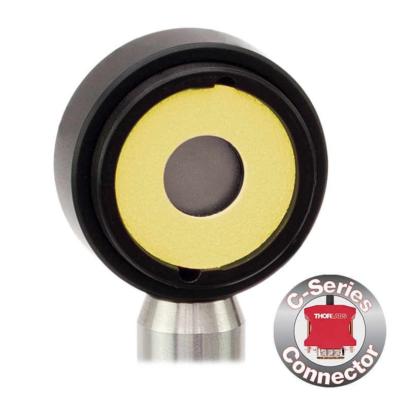
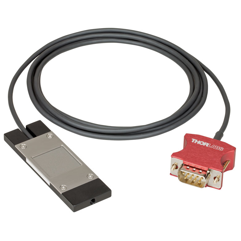
When used with our C-series sensors, Thorlabs' power meter consoles and interfaces recognize the type of connected sensor and measure the current or voltage as appropriate. Our C-series sensors have responsivity calibration data stored in their connectors. The console will read out the responsivity value for the user-entered wavelength and calculate a power or energy reading.
- Photodiode sensors deliver a current that depends on the input optical power and the wavelength. The current is fed into a transimpedance amplifier, which outputs a voltage proportional to the input current. The photodiode's responsivity is wavelength dependent, so the correct wavelength must be entered into the console for an accurate power reading. The console reads out the responsivity for this wavelength from the connected sensor and calculates the optical power from the measured photocurrent.
- Thermal sensors deliver a voltage proportional to the input optical power. Based on the measured sensor output voltage and the sensor's responsivity, the console will calculate the incident optical power.
- Energy sensors are based on the pyroelectric effect. They deliver a voltage peak proportional to the pulse energy. If an energy sensor is recognized, the console will use a peak voltage detector and the pulse energy will be calculated from the sensor's responsivity.
The consoles and interfaces are also capable of providing a readout of the current or voltage delivered by the sensor. Select models also feature an analog output.
Consoles
| Item # | PM100A | PM100D | PM400 | PM320E |
|---|---|---|---|---|
| (Click Photo to Enlarge) |  |
 |
 |
 |
| Key Features | Analog Power Measurements | Digital Power and Energy Measurements | Digital Power and Energy Measurements, Touchscreen Control | Dual Channel |
| Compatible Sensors | Photodiode and Thermal Power | Photodiode and Thermal Power; Pyroelectric | ||
| Housing Dimensions (H x W x D) |
7.24" x 4.29" x 1.61" (184 mm x 109 mm x 41 mm) |
7.09" x 4.13" x 1.50" (180 mm x 105 mm x 38 mm) |
5.35" x 3.78" x 1.16" (136.0 mm x 96.0 mm x 29.5 mm) |
4.8" x 8.7" x 12.8" (122 mm x 220 mm x 325 mm) |
| Channels | 1 | 2 | ||
| External Temperature Sensor Input (Sensor not Included) | - | - | Instantaneous Readout and Record Temperature Over Time | - |
| External Humidity Sensor Input (Sensor not Included) | - | - | Instantaneous Readout and Record Humidity Over Time | - |
| GPIO Ports | - | 4, Programmable | - | |
| Source Spectral Correction | - | - | - | |
| Attenuation Correction | - | - | - | |
| External Trigger Input | - | - | - | |
| Display | ||||
| Type | Mechanical Needle and LCD Display with Digital Readout | 320 x 240 Pixel Backlit Graphical LCD Display | Protected Capacitive Touchscreen with Color Display | 240 x 128 Pixels Graphical LCD Display |
| Dimensions | Digital: 1.9" x 0.5" (48.2 mm x 13.2 mm) Analog: 3.54" x 1.65" (90.0 mm x 42.0 mm) |
3.17" x 2.36" (81.4 mm x 61.0 mm) |
3.7" x 2.1" (95 mm x 54 mm) |
3.7" x 2.4" (94.0 mm x 61.0 mm) |
| Refresh Rate | 20 Hz | 10 Hz (Numerical) 25 Hz (Analog Simulation) |
20 Hz | |
| Measurement Viewsa | ||||
| Numerical | ||||
| Mechanical Analog Needle | - | - | - | |
| Simulated Analog Needle | - | |||
| Bar Graph | - | |||
| Trend Graph | - | |||
| Histogram | - | - | ||
| Statistics | ||||
| Memory | ||||
| Type | - | SD Card | NAND Flash | - |
| Size | - | 2 GB | 4 GB | - |
| Power | ||||
| Battery | LiPo 3.7 V 1300 mAh | LiPo 3.7 V 2600 mAh | - | |
| External | 5 VDC via USB or Included AC Adapter | 5 VDC via USB | Selectable Line Voltage: 100 V, 115 V, 230 V (±10%) | |
Interfaces
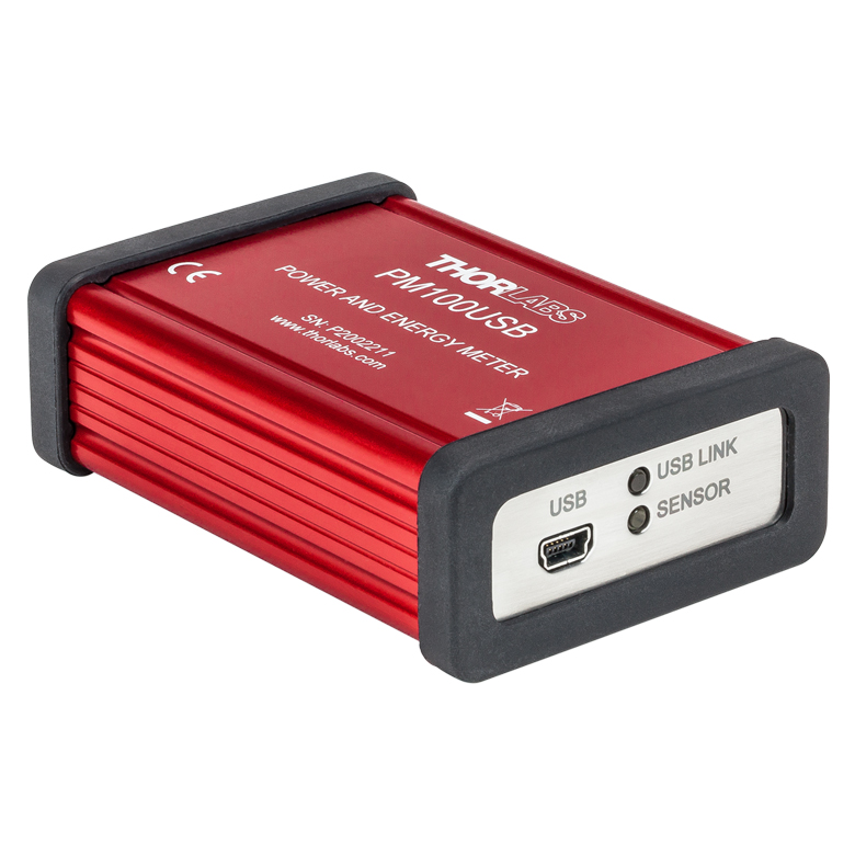
| Item # | PM101 | PM102 | PM101A | PM102A | PM101R | PM101U | PM102U | PM100USB |
|---|---|---|---|---|---|---|---|---|
| (Click Photo to Enlarge) |  |
 |
 |
 |
 |
 |
 |
 |
| Key Features | USB, RS232, UART, and Analog Operation |
USB and Analog SMA Operation | USB and RS232 Operation | USB Operation | USB Operation | |||
| Compatible Sensors | PM101 Series: Photodiode and Thermal Power PM102 Series: Thermal Power and Thermal Position & Power |
Photodiode and Thermal Power; Pyroelectric |
||||||
| Housing Dimensions (H x W x D) |
3.80" x 2.25" x 1.00" (96.5 x 57.2 x 25.4 mm) |
3.94" x 2.25" x 1.00" (100.0 x 57.2 x 25.4 mm) |
3.78" x 2.25" x 1.00" (95.9 x 57.2 x 25.4 mm) |
3.68" x 2.25" x 1.00" (93.6 x 57.2 x 25.4 mm) |
3.67" x 2.38 " x 1.13" (93.1 x 60.4 x 28.7 mm) |
|||
| Channels | 1 | |||||||
| External Temperature Sensor Input (Sensor Not Included) |
NTC Thermistor | - | ||||||
| External Humidity Sensor Input (Sensor not Included) |
- | |||||||
| GPIO Ports | - | |||||||
| Source Spectral Correction | - | |||||||
| Attenuation Correction | - | |||||||
| External Trigger Input | - | |||||||
| Display | ||||||||
| Type | No Built-In Display; Controlled via GUI for PC | |||||||
| Refresh Rate | Up to 1000 Hza | Up to 300 Hza | ||||||
| Measurement Viewsb | ||||||||
| Numerical | Requires PCb | |||||||
| Mechanical Analog Needle | - | |||||||
| Simulated Analog Needle | Requires PCb | |||||||
| Bar Graph | Requires PCb | |||||||
| Trend Graph | Requires PCb | |||||||
| Histogram | Requires PCb | |||||||
| Statistics | Requires PCb | |||||||
| Memory | ||||||||
| Type | Internal Non-Volatile Memory for All Settings | - | ||||||
| Size | - | |||||||
| Power | ||||||||
| Battery | - | |||||||
| External | 5 VDC via USB or 5 to 36 VDC via DA-15 |
5 VDC via USB | ||||||

Click to Enlarge
S120C and CP44F Quick-Release Mount
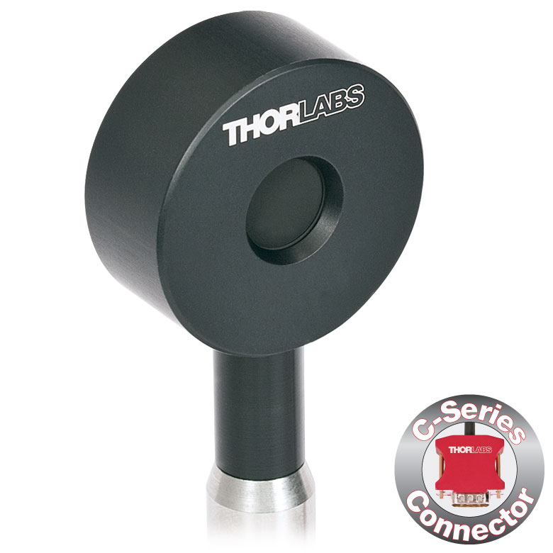
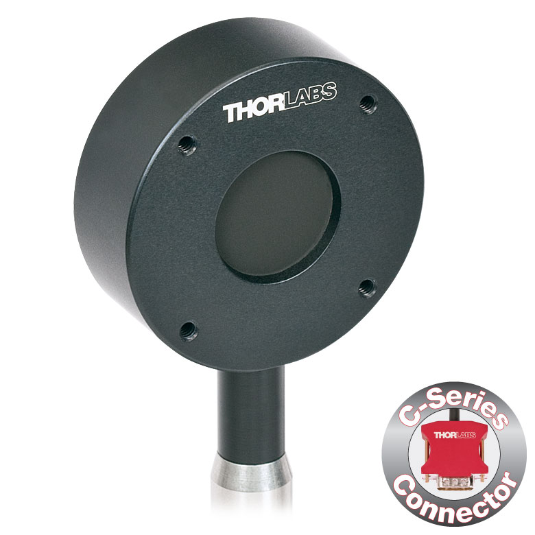
- For General Purpose Optical Power Measurements
- Integrated Viewing Target for Easy Sensor Alignment
- Ø9.5 mm Sensor Aperture
- Sensor, Protective Cap, IR Target, and Thread Adapter Included
- Fiber Adapters Available Separately (See Table Below)
- See the Full Web Presentation for More Information
These Standard Photodiode Power Sensors are ideal for metering low power coherent and incoherent sources from the UV to the NIR. Each NIST-Traceable, calibrated sensor features an integrated viewing target for easy alignment, enhanced shielding against electromagnetic interference, an over-temperature-alert device, and a large Ø9.5 mm sensor aperture. The sensors are compatible with 30 mm cage systems, Ø1/2" posts, and SM1 (1.035"-40) lens tubes, and are ideal for free-space and fiber-coupled sources.
Thorlabs offers a recalibration service for these photodiode power sensors, which can be ordered below (see Item # CAL1 for Si sensors and Item # CAL2 for Ge sensors).
| Item #a | S120VC | S120C | S121C | S122C |
|---|---|---|---|---|
| Sensor Image (Click the Image to Enlarge) |
|
|
|
|
| Aperture Size | Ø9.5 mm | |||
| Wavelength Range | 200 - 1100 nm | 400 - 1100 nm | 400 - 1100 nm | 700 - 1800 nm |
| Power Range | 50 nW - 50 mW | 500 nW - 500 mW | 50 nW - 40 mW | |
| Detector Type | Si Photodiode (UV Extended) | Si Photodiode | Ge Photodiode | |
| Linearity | ±0.5% | |||
| Resolutionb | 1 nW | 10 nW | 2 nW | |
| Measurement Uncertaintyc | ±3% (440 - 980 nm) ±5% (280 - 439 nm) ±7% (200 - 279 nm, 981 - 1100 nm) |
±3% (440 - 980 nm) ±5% (400 - 439 nm) ±7% (981 - 1100 nm) |
±5% | |
| Responsivityd (Click for Plot) |  Raw Data |
 Raw Data |
 Raw Data |
 Raw Data |
| Coating/Diffuser | Reflective ND (OD1.5)e | Reflective ND (OD1)f | Reflective ND (OD2)g | Absorptive ND (Schott NG9) |
| Head Temperature Measurement | NTC Thermistor 4.7 kΩ | |||
| Housing Dimensions | Ø30.5 mm x 12.7 mm | |||
| Cable Length | 1.5 m | |||
| Post Mountinge,f,g | Universal 8-32 / M4 Tap, Post Not Included | |||
| Aperture Thread | External SM1 (1.035"-40) | |||
| Compatible Fiber Adapters | S120-FC, S120-APC, S120-SMA, S120-ST, S120-LC, and S120-SC (Not Included) | |||
| Compatible Consoles | PM400, PM100D, PM100A, and PM320E | |||
| Compatible Interfaces | PM101, PM101A, PM101R, PM101U, and PM100USB | |||
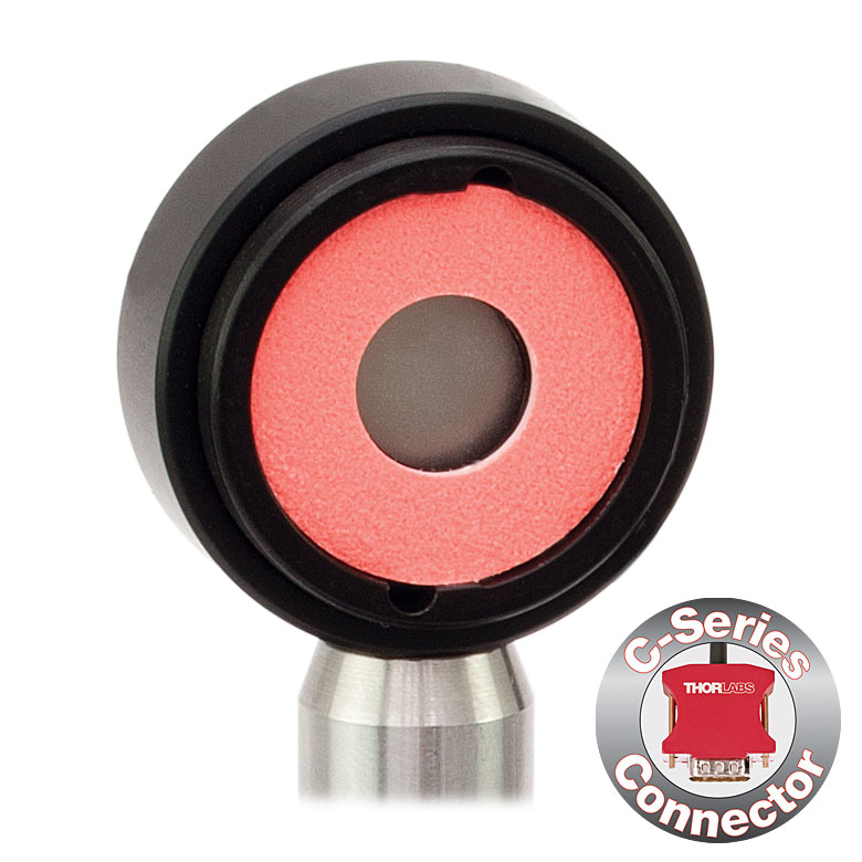

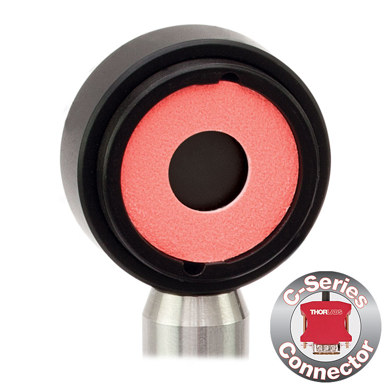


Click for Details S130C Photodiode Sensor Mounted in FiberBench System Using FBSM Mount
- For Optical Power Measurements in Confined Spaces
- Very Slim Design: 5 mm Thin on Sensor Side
- Ø9.5 mm Sensor Aperture
- Slideable ND Filter Automatically Changes Sensor Power Range
- Optional SM1A29 Adapter with VIS/IR Target and External SM1 Threading (More Details)
- Optional FBSM Mount with VIS/IR Target for FiberBench Systems (More Details)
- See the Full Web Presentation for More Information
These Slim Photodiode Power Sensors are designed to take optical source power measurements in locations where space and accessibility are at a premium. The 5 mm thin sensor end can fit between closely spaced optics, cage systems, and other arrangements where standard power meters may not fit. The NIST-Traceable, calibrated sensors also feature a large Ø9.5 mm sensor aperture and slideable neutral density filter for dual power ranges in one compact device.
A separately available SM1A29 adapter can be attached by 2 setscrews to any S130 series power sensor to mount fiber adapters, light shields, filters or any other SM1-threaded (1.035"-40) mechanics or optics. The FBSM Mount allows our S130 series power sensors to be mounted vertically into FiberBench systems for stable mounting with a minimal footprint.
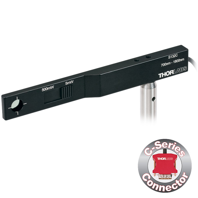
Thorlabs offers a recalibration service for these photodiode power sensors, which can be ordered below (see Item # CAL-S130 for Si sensors and Item # CAL-S132 for Ge sensors).
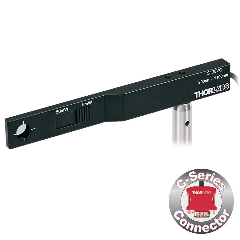
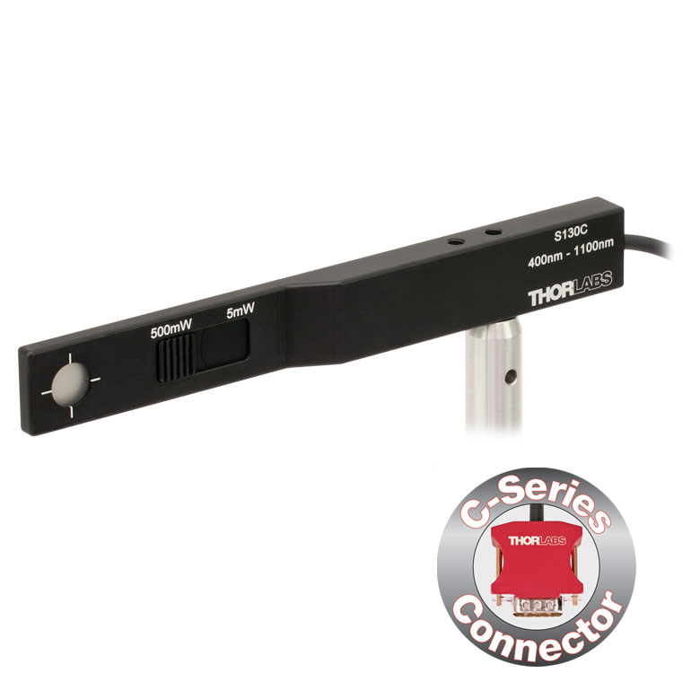
| Item #a | S130VC | S130C | S132C | |
|---|---|---|---|---|
| Sensor Image (Click the Image to Enlarge) |
|
|
|
|
| Aperture Size | Ø9.5 mm | |||
| Wavelength Range | 200 - 1100 nm | 400 - 1100 nm | 700 - 1800 nmb | |
| Power Range (with Filter) |
500 pW - 0.5 mWc (Up to 50 mW)c |
500 pW - 5 mW (Up to 500 mW) |
5 nW - 5 mW (Up to 500 mW) |
|
| Detector Type | Si Photodiode (UV Extended) | Si Photodiode | Ge Photodiode | |
| Linearity | ±0.5% | |||
| Resolution | 100 pWd | 1 nWe | ||
| Measurement Uncertaintyf | ±3% (440 - 980 nm) ±5% (280 - 439 nm) ±7% (200 - 279 nm, 981 - 1100 nm) |
±3% (440 - 980 nm) ±5% (400 - 439 nm) ±7% (981 - 1100 nm) |
±5% | |
| Responsivityg (Click for Plot) | Raw Data |
Raw Data |
Raw Data |
|
| Coating/Diffuser | Reflective ND (OD1.5)c | Reflective ND (OD2)h | Absorptive ND (Schott NG9/KG3)b | |
| Housing Dimensions | 150 mm x 19 mm x 10 mm; 5 mm Thickness on Sensor Side | |||
| Cable Length | 1.5 m | |||
| Post Mounting | 8-32 and M4 Taps | |||
| Adapters (Not Included) | SM1A29: Add SM1 Thread and Viewing Target to Aperture Fiber Adapters Compatible with SM1A29 Adapter: S120-FC, S120-APC, S120-SMA, S120-ST, S120-LC, and S120-SC FBSM: Integrate Sensor into FiberBench Setups |
|||
| Compatible Consoles | PM400, PM100D, PM100USB, PM100A, and PM320E | |||
| Compatible Interfaces | PM101, PM101A, PM101R, PM101U, and PM100USB | |||
| Item #a | S170C |
|---|---|
| Sensor Image (Click Image to Enlarge) |
 |
| Overall Dimensions | 76.0 mm x 25.2 mm x 5.0 mm (2.99" x 0.99" x 0.20") |
| Active Detector Area | 18 mm x 18 mm |
| Input Aperture | 20 mm x 20 mm |
| Wavelength Range | 350 - 1100 nm |
| Optical Power Working Range | 10 nW - 150 mW |
| Detector Type | Silicon Photodiode |
| Linearity | ±0.5% |
| Resolutionb | 1 nW |
| Calibration Uncertaintyc | ±3% (440 - 980 nm) ±5% (350 - 439 nm) ±7% (981 - 1100 nm) |
| Responsivityd (Click for Plot) | Raw Data |
| Neutral Density Filter | Reflective (OD 1.5) |
| Cable Length | 1.5 m |
| Post Mounting | Universal 8-32 / M4 Tap, Post Not Included |
| Compatible Consoles | PM400, PM100D, PM100A, and PM320E |
| Compatible Interfaces | PM101, PM101A, PM101R, PM101U, and PM100USB |
- Wavelength Range: 350 nm to 1100 nm
- Sensitive to Optical Powers from 10 nW to 150 mW
- Designed to Measure Optical Power at the Sample Plane of a Microscope
- Silicon Photodiode with Large 18 mm x 18 mm Active Area
- Sensor Housing Dimensions: 76.0 mm x 25.2 x 5.0 mm
- Index Matching Gel Utilized in Design to Prevent Internal Reflections
- Information Stored in Connector
- Sensor Data
- NIST- and PTB-Traceable Calibration Data
- Post Mountable via 8-32 (M4) Tap
The S170C Microscope Slide Power Sensor Head is a silicon photodiode sensor designed to measure the power at the sample in microscopy setups. The silicon photodiode can detect wavelengths between 350 nm and 1100 nm at optical powers between 10 nW and 150 mW. The sensor head's 76.0 mm x 25.2 mm footprint matches that of a standard microscope slide and is compatible with most standard upright and inverted microscopes.
The photodiode has an 18 mm x 18 mm active area and is contained in a sealed housing behind a neutral density (ND) filter with OD 1.5. A 20 mm x 20 mm indentation around the surface of the ND filter is sized to accept standard microscope cover slips. An immersion medium (water, glycerol, oil) may be placed in this well directly over the ND filter, or a cover slip may be inserted first to simplify clean up. The gap between the photodiode and the neutral density filter has been filled with an index matching gel in order to prevent internal reflections from causing significant measurement errors when using high NA objectives with oil or water.
The bottom of the sensor housing features a laser-engraved grid to aid in aligning and focusing the beam. In standard microscopes, this grid can be used for beam alignment before flipping the sensor head to face the objective for power measurements. In inverted microscopes, turn on the transmitted illuminator to align the grid on the detector housing with the beam, thereby centering the sensor in front of the objective. Alternatively, the diffusive surface of the ND filter can be used as a focusing plane.
Sensor specifications and the NIST- and PTB-traceable calibration data are stored in non-volatile memory in the sensor connector and can be read out by the latest generation of Thorlabs power meters. We recommend yearly recalibration to ensure accuracy and performance. Calibration may be ordered using the CAL1 recalibration service available below. Please contact technical support for more information.
Thorlabs also offers a Microscope Slide Sensor Head with a thermal sensor; for complete specifications, the full presentation can be found here.
| Item #a | S175C |
|---|---|
| Sensor Image (Click Image to Enlarge) |
 |
| Active Detector Area | 18 mm x 18 mm |
| Wavelength Range | 0.3 - 10.6 µm |
| Power Range | 100 µW - 2 W |
| Detector Type | Thermal Surface Absorber (Thermopile) |
| Linearity | ±0.5% |
| Resolutionb | 10 µW |
| Measurement Uncertaintyc | ±3% @ 1064 nm; ±5% @ 300 nm - 10.6 µm |
| Response Time | 3 s (<2 s from 0 to 90%) |
| Housing Dimensions | 76 mm x 25.2 mm x 4.8 mm (2.99" x 0.99" x 0.19") |
| Cable Length | 1.5 m |
| Housing Features | Integrated Glass Cover Engraved Laser Target on Back |
| Post Mounting | N/A |
| Cage Mounting | N/A |
| Aperture Thread | N/A |
| Compatible Consoles | PM400, PM100D, PM100A, and PM320E |
| Compatible Interfaces | PM101, PM101A, PM101R, PM101U, PM102, PM102A, PM102U, and PM100USB |

Click to Enlarge
Typical absorption curve for the S175C (glass and absorber). Note that this curve is representative, and the actual absorption across the spectrum will vary from unit to unit.

Click to Enlarge
The back of the S175C housing is engraved with the sensor specifications and a target for centering the beam on the sensor.
- Wavelength Range: 300 nm - 10.6 µm
- Sensitive to Optical Powers from 100 µW to 2 W
- Designed to Measure Optical Power in the Sample Plane of a Microscope
- Thermal Sensor with 18 mm x 18 mm Active Area
- 76.0 mm x 25.2 mm Footprint Matches Standard Microscope Slides
- Information Stored in Connector
- Sensor Data
- NIST- and PTB-Traceable Calibration Data
- See the Full Web Presentation for More Information
The S175C Microscope Slide Thermal Power Sensor Head is designed to measure the power at the sample in microscopy setups. The thermal sensor can detect wavelengths between 300 nm and 10.6 µm at optical powers between 100 µW and 2 W. The sensor head's 76.0 mm x 25.2 mm footprint matches that of a standard microscope slide and is compatible with most standard upright and inverted microscopes.
The thermal sensor has an 18 mm x 18 mm active area and is contained in a sealed housing behind a glass cover. An immersion medium (water, glycerol, oil) may be placed over the glass cover plate.
As seen in the image to the right, the bottom of the sensor housing features a laser-engraved target to aid in aligning and focusing the beam. In standard microscopes, the target can be used for beam alignment before flipping the sensor head to face the objective for power measurements. In inverted microscopes, turn on the trans-illumination lamp and align the target on the detector housing with the beam; this will center the sensor in front of the objective.
Sensor specifications and the NIST- and PTB-traceable calibration data are stored in non-volatile memory in the sensor connector and can be read out by the latest generation of Thorlabs power meters. We recommend yearly recalibration to ensure accuracy and performance. Calibration may be ordered using the CAL-S200 recalibration service available below. Please contact technical support for more information.
Thorlabs also offers a Microscope Slide Sensor Head with a photodiode sensor for low-power, high-resolution measurements; the full presentation may be found here.

Click to Enlarge
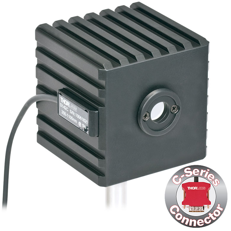
S142C and S140-BFA Bare Fiber Adapter (Sold Separately)

Click to Enlarge
S142C with the S120-FC Fiber Adapter (Included)
- For Measurements Independent of Beam Shape and Entrance Angle
- Integrating Sphere Design Acts as a Diffuser with Minimal Power Loss
- Ø5 mm, Ø7 mm, or Ø12 mm Input Aperture
- Removable S120-FC Fiber Adapter (FC/PC and FC/APC) Included
- Compatible Fiber Adapters for Terminated and Bare Fiber (See Table Below)
- See the Full Web Presentation for More Information
These Integrating Sphere Photodiode Power Sensors are the ideal choice for power measurements independent of beam uniformity, divergence angle, beam shape, or entrance angle, making them excellent for use with fiber sources and off-axis free space sources.
Our integrating spheres are designed for wavelength ranges from the visible through the NIR. Sensor heads for use between 350 and 2500 nm use a single Ø1" or Ø2" sphere made from Zenith® PTFE and feature a black housing to minimize reflected light around the entrance aperture. These sensors use either a silicon photodiode for detection in the 350 - 1100 nm range or an InGaAs photodiode for detection in the 800 - 1700 nm, 900 - 1650 nm, or 1200 - 2500 nm wavelength range.
The S180C integrating sphere for 2.9 - 5.5 µm uses two connected, gold-plated Ø20 mm spheres, with an entrance port in the first sphere and a port for the MCT (HgCdTe) detector located in the second sphere. Compared to single-sphere designs, the two-sphere configuration improves device sensitivity by minimizing the internal sphere surface area while still effectively shielding the detector from direct illumination. This design reduces the effect of input angle, divergence, and beam shape on the measurement result by effectively shielding the photodiode without the use of a baffle or other shielding mechanism.
The integrating spheres below feature large Ø5 mm, Ø7 mm, or Ø12 mm apertures, externally SM1-threaded (1.035"-40) front connections, enhanced shielding against electromagnetic interference, and an over-temperature alert sensor. Because of the large active detector areas of these sensors, the included S120-FC fiber adapter can be used with FC/PC- or FC/APC-terminated fiber. The externally SM1-threaded adapter can be removed using a size 1 screwdriver to place components closer to the window. NIST-traceable data is stored in the sensor connector.
Thorlabs offers a recalibration service for these photodiode power sensors, which can be ordered below. See Item # CAL1 for the S140C and S142C Si sensors; Item # CAL2 for the S144C, S145C, and S146C InGaAs sensors; and Item # CAL4 for the S148C InGaAs sensor or S180C MCT sensor.
| Item #a | S140C | S142C | S144C | S145C | S146C | S148C | S180C |
|---|---|---|---|---|---|---|---|
| Sensor Image (Click the Image to Enlarge) |
 |
 |
 |
 |
 |
|
 |
| Aperture | Ø5 mm | Ø12 mm | Ø5 mm | Ø12 mm | Ø5 mm | Ø7 mm | |
| Wavelength Range | 350 - 1100 nm | 800 - 1700 nm | 900 - 1650 nm | 1200 - 2500 nm | 2.9 µm - 5.5 µm | ||
| Power Range | 1 µW - 500 mW | 1 µW - 5 W | 1 µW - 500 mW | 1 µW - 3 W | 10 µW - 20 W | 1 µW - 1 W | 1 µW - 3 W |
| Detector Type | Si Photodiode | InGaAs Photodiode | MCT (HgCdTe) Photodiode |
||||
| Linearity | ±0.5% | ||||||
| Resolutionb | 1 nW | 10 nW | 1 nW | 10 nW | |||
| Measurement Uncertaintyc |
±3% (440 - 980 nm) ±5% (350 - 439 nm) ±7% (981 - 1100 nm) |
±5% | |||||
| Responsivityd (Click for Plot) |
 Raw Data |
 Raw Data |
 Raw Data |
 Raw Data |
 Raw Data |
 Raw Data |
| Integrating Sphere Material (Size) |
Zenith® PTFE (Ø1") |
Zenith® PTFE (Ø2") |
Zenith® PTFE (Ø1") |
Zenith® PTFE (Ø2") |
Zenith® PTFE (Ø1") |
Gold Plating (Two Ø20 mm Spheres) |
|
| Head Temperature Measurement |
NTC Thermistor 4.7 kΩ | ||||||
| Housing Dimensions |
Ø45 mm x 30.5 mm | 70 mm x 74 mm x 70 mm | Ø45 mm x 30.5 mm | 70 mm x 74 mm x 70 mm | Ø45 mm x 30.5 mm | 59.0 mm x 50.0 mm x 28.5 mm |
|
| Cable Length | 1.5 m | ||||||
| Post Mounting | 8-32 and M4 Taps | ||||||
| Aperture Thread | Included Adapter with SM1 (1.035"-40) External Thread | ||||||
| Compatible Fiber Adapters |
S120-FC (Included) S120-APC, S120-SMA, S120-ST, S120-SC, S120-LC, and S140-BFA Bare Fiber Adapter (Not Included) |
||||||
| Compatible Consoles | PM400, PM100D, PM100A, and PM320E | ||||||
| Compatible Interfaces | PM101, PM101A, PM101R, PM101U, and PM100USB | ||||||

Click to Enlarge
PM100D with S150C Sensor and FC Cable
- For Fiber-Based Optical Power Measurements
- Compact Sensor Integrated into the Connector
- Integrated Design for use in the Field and Lab
- Includes PM20-FC Fiber Adapter
- S150C and S151C Sensors also Include PM20-SMA Adapters
- Compatible FC/APC, LC/PC, SC/PC, and ST Fiber Adapters Also Available (See Table Below)
- See the Full Web Presentation for More Information
The S15xC Compact Fiber Photodiode Power Sensor is designed to take power measurements from a wide variety of fiber coupled sources. The compact sensor, integrated into the power meter connector, features a unique integrated design housing the photodiode sensor, fiber coupling, and NIST-traceable data. Standard FC (and SMA - S150C and S151C) connectors are easily interchanged with a variety of standard fiber connectors.
Thorlabs offers a recalibration service for these photodiode power sensors, which can be ordered below (see Item # CAL1 for Si sensors and Item # CAL2 for InGaAs sensors).
| Item #a | S150C | S151C | S154C | S155C |
|---|---|---|---|---|
| Sensor Image (Click the Image to Enlarge) |
|
|
|
|
| Included Connectors | FCb & SMA | FCb | ||
| Wavelength Range | 350 - 1100 nm | 400 - 1100 nm | 800 - 1700 nm | |
| Power Range | 100 pW to 5 mW (-70 dBm to +7 dBm) |
1 nW to 20 mW (-60 dBm to +13 dBm) |
100 pW to 3 mW (-70 dBm to +5 dBm) |
1 nW to 20 mW (-60 dBm to +13 dBm) |
| Detector Type | Si Photodiode | InGaAs Photodiode | ||
| Linearity | ±0.5% | |||
| Resolutionc | 10 pW (-80 dBm) | 100 pW (-70 dBm) | 10 pW (-80 dBm) | 100 pW (-70 dBm) |
| Measurement Uncertaintyd | ±3% (440 - 980 nm) ±5% (350 - 439 nm) ±7% (981 - 1100 nm) |
±3% (440 - 980 nm) ±5% (400 - 439 nm) ±7% (981 - 1100 nm) |
±5% | |
| Responsivityf (Click for Details) |  Raw Data |
 Raw Data |
 Raw Data |
 Raw Data |
| Coating/Diffuser | N/A | Absorptive ND (Schott NG3) | N/A | |
| Head Temperature Measuremente | NTC Thermistor 3 kΩ | |||
| Aperture Thread | External SM05 (0.535"-40) | |||
| Fiber Adapters | Included: PM20-FC and PM20-SMA Optional: PM20-APC, PM20-LC, PM20-SC, and PM20-ST |
Included: PM20-FC Optional: PM20-APC, PM20-LC, PM20-SC, PM20-ST, and PM20-SMA |
||
| Compatible Consoles | PM400, PM100D, PM100A, and PM320E | |||
| Compatible Interfaces | PM101, PM101A, PM101R, PM101U, and PM100USB | |||


| Item #a | S401C | S405C |
|---|---|---|
| Sensor Image (Click the Image to Enlarge) |
 |
 |
| Wavelength Range | 190 nm - 20 µm | 190 nm - 20 µm |
| Optical Power Range | 10 µW - 1 W (3 Wb) | 100 µW - 5 W |
| Input Aperture Size | Ø10 mm | Ø10 mm |
| Active Detector Area |
10 mm x 10 mm | 10 mm x 10 mm |
| Max Optical Power Density | 500 W/cm² (Avg.) | 1.5 kW/cm² (Avg.) |
| Detector Type | Thermal Surface Absorber (Thermopile) with Background Compensation |
Thermal Surface Absorber (Thermopile) |
| Linearity | ±0.5% | ±0.5% |
| Resolutionc | 1 µW | 5 µW |
| Measurement Uncertaintyd | ±3% @ 1064 nm ±5% @ 190 nm - 10.6 µm |
±3% @ 1064 nm ±5% @ 250 nm - 17 µm |
| Response Timee | 1.1 s | 1.1 s |
| Cooling | Convection (Passive) | |
| Housing Dimensions (Without Adapter) |
(1.30" x 1.69" x 0.59") |
40.6 mm x 40.6 mm x 16.0 mm (1.60" x 1.60" x 0.63") |
| Temperature Sensor (In Sensor Head) |
NTC Thermistor | NTC Thermistor |
| Cable Length | 1.5 m | |
| Post Mounting | Universal 8-32 / M4 Taps (Post Not Included) |
Universal 8-32 / M4 Taps (Post Not Included) |
| 30 mm Cage Mounting | - | Two 4-40 Tapped Holes & Two Ø6 mm Through Holes |
| Aperture Threads | - | Internal SM05 |
| Accessories | Externally SM1-Threaded Adapter Light Shield with Internal SM05 Threading |
Externally SM1-Threaded Adapter |
| Compatible Consoles | PM400, PM100D, PM100A, and PM320E | |
| Compatible Interfaces | PM101, PM101A, PM101R, PM101U, PM102, PM102A, PM102U and PM100USB | |
- High Resolution of 1 μW or 5 μW
- S401C and S405C Have Thermistors Used to Monitor Temperature of Sensor Head
- S401C: Background Compensation for Low-Drift Measurements
- S405C: Accommodates Average Optical Power Densities up to 1.5 kW/cm²
- See the Full Web Presentation for More Information

Click to Enlarge
S401C Thermal Sensor with Included Light Shield
Thorlabs offers two broadband thermal power sensors designed to measure low optical power sources with high resolution. Each thermal sensor's broadband coating has a flat spectral response over a wide wavelength range, as shown in the plot below.
An aperture size of Ø10 mm allows for easy alignment and measurement of large-spot-size laser sources. For easy integration with Thorlabs' lens tube systems and SM1-threaded (1.035"-40) fiber adapters, each sensor has either external SM1 threading or includes an externally SM1-threaded adapter.
The S401C uses active thermal background compensation to provide low-drift power measurements. This is implemented through the use of two similar sensor circuits. One sensor circuit is the type all thermal power sensors share: it measures heat flow from light absorber to heat sink. The other sensor circuit monitors the ambient temperature. It is located within the housing and measures heat flow from heat sink towards the absorber. The measurements of the two sensor circuits are subtracted, which minimizes the effect of thermal drift on the laser power measurement. (For information about how the external thermal disturbances can affect thermal power sensor readings, see the Operation tab.) The broadband coating used on this thermal sensor offers high absorption at wavelengths between 0.19 and 20 µm (shown in the graph), which makes the sensor ideal for use with aligning and measuring Mid-IR Quantum Cascade Lasers (QCLs). The included, internally SM05-threaded (0.535"-40) light shield is shown in the photo to the right.
The S405C has internal SM05 (0.535"-40) threading that is directly compatible with SM05 lens tubes, and it can also connect directly to Thorlabs' 30 mm Cage Systems.
Thorlabs offers a recalibration service for these sensors, which can be ordered below (see Item # CAL-S200).

Click to Enlarge
The S405 shares the same absorption curve with the S415C, S425C, and S245C-L. (All are sold below.)
| Item #a | S415C | S425C |
|---|---|---|
| Sensor Image (Click Image to Enlarge) |
 |
 |
| Wavelength Range | 190 nm - 20 µm | 190 nm - 20 µm |
| Optical Power Range | 2 mW - 10 W (20 Wb) | 2 mW - 10 W (20 Wb) |
| Input Aperture Size | Ø15 mm | Ø25.4 mm |
| Active Detector Area |
Ø15 mm | Ø27 mm |
| Max Optical Power Density |
1.5 kW/cm² (Avg.) | 1.5 kW/cm² (Avg.) |
| Detector Type | Thermal Surface Absorber (Thermopile) | |
| Linearity | ±0.5% | ±0.5% |
| Resolutionc | 100 µW | 100 µW |
| Measurement Uncertaintyd |
±3% @ 1064 nm ±5% @ 250 nm - 17 µm |
±3% @ 1064 nm ±5% @ 250 nm - 17 µm |
| Response Timee | 0.6 s | 0.6 s |
| Cooling | Convection (Passive) | |
| Housing Dimensions (Without Adapter) |
(2.00" x 2.00" x 1.38") |
(2.00" x 2.00" x 1.38") |
| Temperature Sensor (In Sensor Head) |
NTC Thermistor | |
| Cable Length | 1.5 m | |
| Post Mounting | Universal 8-32 / M4 Taps (Post Not Included) |
Universal 8-32 / M4 Taps (Post Not Included) |
| 30 mm Cage Mounting | - | - |
| Aperture Threads | Internal SM1 | Internal SM1 |
| Removable Heatsink | Yes | Yes |
| Accessories | Externally SM1-Threaded Adapter | Externally SM1-Threaded Adapter |
| Compatible Consoles | PM400, PM100D, PM100A, and PM320E | |
| Compatible Interfaces | PM101, PM101A, PM101R, PM101U, PM102, PM102A, PM102U and PM100USB | |
- 100 µW Optical Power Resolution
- Thermistors Used to Monitor Temperature of Sensor Head
- Removable Heat Sinks Included
- See the Full Web Presentation for More Information
These thermal power sensors are designed for general broadband power measurements of low and medium power light sources. All include an externally SM1-threaded (1.035"-40) adapter, with threading concentric with the input aperture. The adapters are useful for mounting Ø1" Lens Tubes and Fiber Adapters (available below). The apertures of the S415C and S425C have internal SM1 threading.
These sensors operate with fast (<0.6 s) natural response times, and their removable heat sinks provide a high degree of flexibility to those interested in integrating them into custom setups or replacing the included heat sink with one that is water or fan cooled. If replacing the heat sink, please note that the replacement must provide heat dissipation adequate for the application.
Thorlabs offers a recalibration service for these sensors, which can be ordered below (see Item # CAL-S200).

Click to Enlarge
The absorption curves of each of the thermal power sensors designed for use with low and medium power optical sources.

Click to Enlarge
The absorption curves of each of the thermal power sensors designed for use with low and medium power optical sources.
- Thermistors Used to Monitor Temperature of Sensor Head
- S322C Has 4-40 Taps for Use with Our 30 mm Cage Systems
- S350C Has Ø40 mm Aperture Well Suited to Excimer and Other Lasers with Large Spot Sizes
- S425C-L Features Removable Heat Sink
- S322C is Fan Cooled with an Optical Power Range up to 200 W
- See the Full Web Presentation for More Information
These thermal power sensors are designed for general broadband power measurements of low and medium power light sources. With the exception of the S350C, all include an adapter with external SM1 (1.035"-40) threading concentric with the input aperture. This allows the sensors to be integrated into existing Ø1" lens tube systems in addition to being compatible with fiber adapters (available below). The aperture of the S425C-L has internal SM1 threading.
The S425C-L operates with a fast (<0.6 s) natural response time and has a removable heat sink, which provides a high degree of flexibility to those interested in integrating them into custom setups or replacing the included heat sink with one that is water or fan cooled. If replacing the heat sink, please note that the replacement must provide heat dissipation adequate for the application.
Thorlabs offers a recalibration service for these sensors, which can be ordered below (see Item # CAL-S200).
| Item #a | S350C | S425C-L | S322C |
|---|---|---|---|
| Sensor Image (Click Image to Enlarge) |
 |
 |
 |
| Wavelength Range | 190 nm- 1.1 µm, 10.6 µm | 190 nm - 20 µm | 250 nm - 11 µm |
| Optical Power Range | 10 mW - 40 W (60 Wb) | 2 mW - 50 W (75 Wb) | 100 mW - 200 W (250 Wb) |
| Input Aperture Size | Ø40 mm | Ø25.4 mm | Ø25 mm |
| Active Detector Area |
Ø40 mm | Ø27 mm | Ø25 mm |
| Max Optical Power Density | 2 kW/cm² (Avg.) | 1.5 kW/cm² (Avg.) | 4 kW/cm² (Avg., CO2) |
| Detector Type | Thermal Surface Absorber (Thermopile) | ||
| Linearity | ±1% | ±0.5% | ±1% |
| Resolutionc | 1 mW | 100 µW | 5 mW |
| Measurement Uncertaintyd | ±3% @ 351 nm ±5% @ 190 nm - 1100 nm |
±3% @ 1064 nm ±5% @ 250 nm - 17 µm |
±3% @ 1064 nm ±5% @ 266 nm - 1064 nm |
| Response Timee | 9 s (1 s from 0 to 90%) |
0.6 s | 5 s (1 s from 0 to 90%) |
| Cooling | Convection (Passive) | Forced Air with Fanf | |
| Housing Dimensions (Without Adapter, if Applicable) |
100 mm x 100 mm x 54.2 mm (3.94" x 3.94" x 2.13") |
100.0 mm x 100.0 mm x 58.0 mm (3.94" x 3.94" x 2.28") |
100 mm x 100 mm x 86.7 mm (3.94" x 3.94" x 3.41") |
| Temperature Sensor (In Sensor Head) |
NTC Thermistor | ||
| Cable Length | 1.5 m | ||
| Post Mounting | M6 Threaded Taps, Includes Ø1/2" Post, 75 mm Long |
Universal 8-32 / M4 Taps (Post Not Included) |
M6 Threaded Taps, Includes Ø1/2" Post, 75 mm Long |
| 30 mm Cage Mounting | - | - | Four 4-40 Tapped Holes |
| Aperture Threads | - | Internal SM1 | - |
| Removable Heatsink | - | Yes | - |
| Accessories | - | Externally SM1-Threaded Adapter | Externally SM1-Threaded Adapter |
| Compatible Consoles | PM400, PM100D, PM100A, and PM320E | ||
| Compatible Interfaces | PM101, PM101A, PM101R, PM101U, PM102, PM102A, PM102U and PM100USB | ||
| Item #a | S370C | S470C |
|---|---|---|
| Sensor Image (Click the Image to Enlarge) |
 |
 |
| Wavelength Range | 400 nm - 5.2 µm | 250 nm - 10.6 µm |
| Optical Power Range | 10 mW - 10 W (15 Wb) | 100 µW - 5 W (Pulsed and CW) |
| Input Aperture Size | Ø25 mm | Ø15 mm |
| Active Detector Area |
Ø25 mm | Ø16 mm |
| Max Optical Power Density | 35 W/cm² (Avg.); 100 GW/cm² (Peak) | |
| Detector Type | Thermal Volume Absorber (Thermopile) | |
| Linearity | ±1% | ±0.5% |
| Resolutionc | 250 µW | 10 µW |
| Measurement Uncertaintyd | ±3% @ 1064 nm ±5% @ 400 nm - 1064 nm |
±3% @ 1064 nm ±5% @ 250 nm - 10.6 µm |
| Response Timee | 45 s (3 s from 0 to 90%) |
6.5 s (<2 s from 0 to 90%) |
| Cooling | Convection (Passive) | |
| Housing Dimensions (Without Adapter, if Applicable) |
(2.95" x 2.95" x 2.02") |
(1.77" x 1.77" x 0.71") |
| Temperature Sensor (In Sensor Head) |
N/A | N/A |
| Cable Length | 1.5 m | |
| Post Mounting | M6 Threaded Taps, Includes Ø1/2" Post, 75 mm Long |
Universal 8-32 / M4 Tap (Post Not Included) |
| 30 mm Cage Mounting | Four 4-40 Tapped Holes | - |
| Aperture Threads | - | External SM1 |
| Accessories | - | |
| Compatible Consoles | PM400, PM100D, PM100A, and PM320E | |
| Compatible Interfaces | PM101, PM101A, PM101R, PM101U, PM102, PM102A, PM102U and PM100USB | |
- Designed for Optical Power Measurements of Nd:YAG Lasers
- Ideal for Applications with High Peak Pulse Powers
- S370C: Ø25 mm Aperture for Large-Spot-Size Beams
- S470C: High-Sensitivity for High-Peak-Power Pulses with Low Average Power
- See the Full Web Presentation for More Information
The S370C and S470C Thermal Sensors are designed to measure short and highly energetic laser pulses. All of these units are post-mountable for free-space applications and feature NIST-traceable data stored in the sensor connector.
These thermal power sensors are unique in that they have thermal volume absorbers, where our other thermal power sensors have thermal surface absorbers. The volume absorber consists of a Schott glass filter. Incident pulses are absorbed and the heat is distributed throughout the volume. In this way, pulses that would have damaged the absorption coating of a thermal surface absorber are safely measured by these thermal volume absorbers.
The S370C features a large Ø25 mm aperture ideal for large-spot-size beams, and it is compatible with average powers from 10 mW to 10 W (CW).
In comparison, the S470C is faster, as the glass absorber volume is reduced and other design parameters have been optimized for speed. This results in a different optical power range, with the ability to measure powers down to 100 µW. The Ø15 mm aperture is of the S470C is smaller, and it has a lower max average power of 5 W. Its 10 µW resolution is better than the 250 µW resolution of the S370C.
Thorlabs offers a recalibration service for these sensors, which can be ordered below (see Item # CAL-S200).

Click to Enlarge
This absorption curve is shown over a broader wavelength range than the sensors' operating ranges. See the table for the operating wavelength range of each sensor.

Click to Enlarge
ES220C Sensor Mounted in a 30 mm Cage System
- For General Purpose and High Energy Optical Pulse Measurements
- Black Broadband Coating with Flat Response Over a Wide Wavelength Range
- Ceramic Coating with High Damage Thresholds for High-Energy-Density Lasers
- Sensor Areas from Ø11 mm to Ø45 mm
- BNC Connector for Oscilloscope Use
- C-Series Connector Adapter for Use with Compatible Thorlabs Consoles and Interfaces (See Table Below)
- See the Full Web Presentation for More Information
These Pyroelectric Sensors are designed to measure pulsed coherent and incoherent sources. Pyroelectric sensors are not suited for CW measurements, as they convert energy from light pulses into voltage pulses. A black broadband or ceramic coating is used for low or high power measurements, respectively. Large sensor areas from
Ø11 mm - Ø45 mm allow easy alignment. The energy sensors features BNC connectors for use with an oscilloscope, as well as standard power meter connectors which contain NIST and PTB-traceable calibration data.
These sensors are not compatible with the PM100A Analog Power Meter Console or the PM101 Series Power Meter Interfaces.
Thorlabs offers a recalibration service for these energy sensors, which can be ordered below (see Item # CAL-S200).
| Item #a | ES111C | ES120C | ES145C | ES220C | ES245C |
|---|---|---|---|---|---|
| Sensor Image (Click the Image to Enlarge) |
 |
 |
 |
 |
 |
| Aperture Size | Ø11 mm | Ø20 mm | Ø45 mm | Ø20 mm | Ø45 mm |
| Wavelength Range | 0.185 - 25 µm | ||||
| Energy Range | 10 µJ - 150 mJ | 100 µJ - 500 mJ | 500 µJ - 2 J | 500 µJ - 3 J | 1 mJ - 15 J |
| Detector Type | Pyroelectric Energy Sensor with Black Broadband Coating | Pyroelectric Energy Sensor with Ceramic Coating | |||
| Resolution | 100 nJ | 1 µJ | 1 µJ | 25 µJ | 50 µJ |
| Linearity | ±1% | ||||
| Measurement Uncertainty | ±5% @ 0.185 - 25 µm | ||||
| Housing Dimensions | Ø36 mm x 16 mm | Ø50 mm x 18 mm | Ø75 mm x 21 mm | Ø50 mm x 18 mm | Ø75 mm x 21 mm |
| Cable Length | 1.5 m | ||||
| Post Mounting | 8-32 Mounting Thread, 8-32 and M4 Insulating Adapters Included | ||||
| Cage Mounting | N/A | Four 4-40 Taps for 30 mm Cage Systems |
N/A | Four 4-40 Taps for 30 mm Cage Systems |
N/A |
| Compatible Consoles | PM400, PM100D, and PM320E | ||||
| Compatible Interfaces | PM100USB | ||||