 Products Home / Optical Systems / Objective Lenses, Scan Lenses, and Tube Lenses / Phase Contrast Objectives
Phase Contrast Objectives

- Positive Phase Contrast Objectives
- Dark Low Low and Apodized Dark Low Options Available
- Plan Fluorite and Achromat Designs
- Condenser Phase Mask Included
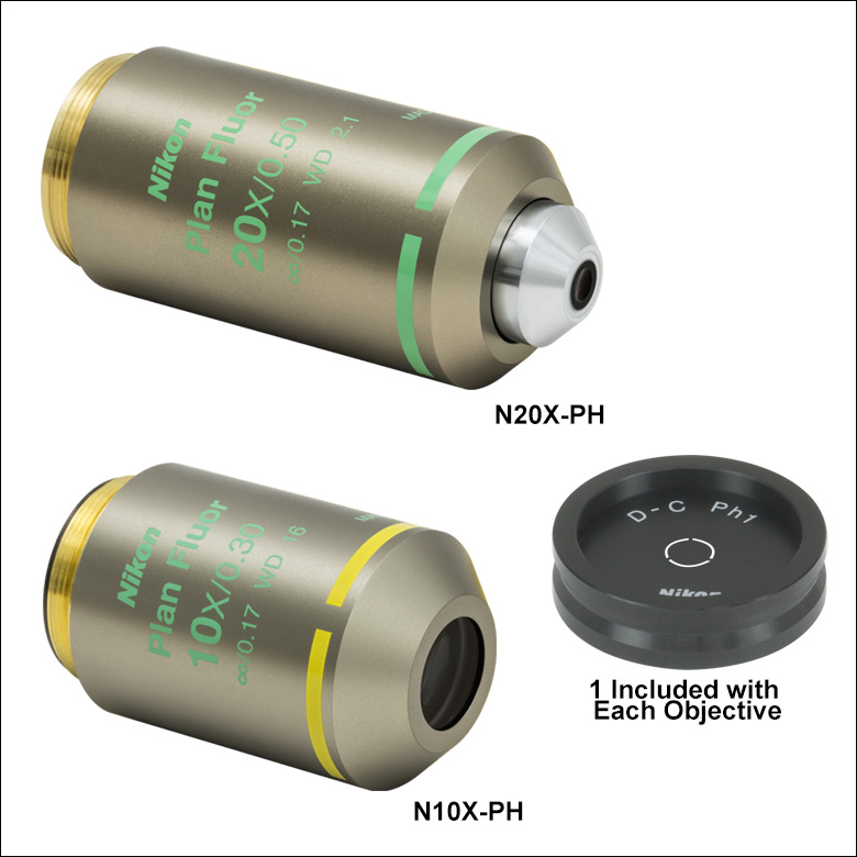
N20X-PH
20X Dark Low Low
N10X-PH
10X Dark Low Low
N10X-PHE
10X Apodized Dark Low
Brightfield (Left) and Phase Contrast (Right) Images of Mouse Kidney Cells
Ph1 Condenser Phase Annulus
(Included)


Please Wait
| Objective Lens Selection Guide |
|---|
| Objectives |
| Super Apochromatic Microscope Objectives Microscopy Objectives, Dry Microscopy Objectives, Oil Immersion Physiology Objectives, Water Dipping or Immersion Phase Contrast Objectives Long Working Distance Objectives Reflective Microscopy Objectives UV Microscopy Objectives VIS and NIR Focusing Objectives |
| Scan Lenses and Tube Lenses |
| Scan Lenses F-Theta Scan Lenses Infinity-Corrected Tube Lens |

Did You Know?
Multiple optical elements, including the microscope objective, tube lens, and eyepieces, together define the magnification of a system. See the Magnification & FOV tab to learn more.

Click to Enlarge
Mouse Kidney Cells Imaged Using Brightfield Illumination

Click to Enlarge
Same Sample Imaged Using Phase Contrast
Thorlabs provides a selection of Nikon dry objectives designed for phase contrast microscopy. These objectives use a phase plate at the rear focal plane of the objective with a coated phase ring. The ring introduces a +¼λ phase shift to light passing through the ring. Light which does not pass through the ring, which consists primarily of light scattered by sample features, receives a typical phase shift of -¼λ. This results in a 180° phase shift (typical) between background and scattered light. Constructive and destructive interference between light scattered by the sample and background illumination results in higher image contrast than can be achieved through brightfield illumination alone.
To achieve optimum phase contrast, these phase contrast objectives should be used with the included Ph1 phase annulus; the diameter of the annulus is paired to the diameter of the phase ring of the objective. The phase mask should be installed in a Nikon condenser containing a compatible slot, such as the CSC1002 condenser. See the Phase Contrast tab for details.
These objectives feature M25 x 0.75 threading and a 60 mm parfocal length; to use one of these objectives alongside an objective with a longer parfocal length, such as for multiphoton microscopy, we offer the PLE153 Parfocal Length Extender to increase the parfocal length from 60 mm to 75 mm. To convert M25 x 0.75 threads to M32 x 0.75 threads, we offer the M32M25S thread adapter.
These objectives are designed for tube lenses with a 200 mm focal length, such as our series of TTL200 infinity-corrected tube lenses.

Click to Enlarge
Information on Either Side of a Phase Contrast Objective
(See Objective Tutorial Tab for More Information About Microscope Objectives)

Click to Enlarge
Phase contrast microscopy beam diagram. The condenser annulus allows only a hollow focused cone of light to illuminate the sample (light blue); after passing through the sample, scattered light (orange) is delayed by -¼λ (typical). When undeflected light - primarily background illumination - passes through the phase ring of the phase plate, it is shifted +¼λ and dimmed 50% (dark blue). These phase shifts result in constructive and destructive interference between background and scattered light at the image plane.
Principles of Phase Contrast Microscopy
When imaging a translucent sample via brightfield trans-illumination, the contrast between the sample and background can be minimal, as it only depends on absorption. Phase contrast microscopy increases image contrast by converting phase changes into amplitude changes at the image plane.
In the case of positive phase contrast, a high-refractive-index plate inside the objective utilizes a metal-coated, etched ring to both reduce transmission by 50% and introduce a +¼λ phase shift to light traveling through the ring. When used with the matching condenser annulus, the beam passing through the phase ring primarily contains background, unscattered light, while the beam passing elsewhere through the plate corresponds to light scattered by the sample. Light interaction with the specimen results in a typical -¼λ phase shift for cellular structures. The net 180° phase difference (typical) between the unscattered and scattered portions of the beam results in constructive and destructive interference at the image plane. The 50% reduction in background light results in a more comparable intensity between background and scattered light, additionally improving contrast. Compared to brightfield images, phase contrast images exhibit larger, phase-dependent contrast with lower background signal. Because these objectives utilize positive phase contrast, the resulting image will be dark with a light background.

Click to Enlarge
In brightfield, when imaging translucent samples, image contrast, ΔI, only indicates absorption of light by the sample. In phase contrast, the phase plate converts phase differences due to scattering in the sample into amplitude changes via constructive and destructive interference between background and scattered light; this results in increased contrast between the background and the sample.
Objective Identification

Note: These microscope objectives serve only as examples. The format of the engraved specifications will vary between objectives and manufacturers.
Types of Objectives
Thorlabs offers several types of objectives from Nikon, Olympus, and Mitutoyo. This guide describes the features and benefits of each type of objective.
Dry or Oil-Immersion Objectives
This designation refers to the medium that should be present between the front of the objective and the cover glass of the microscope slide. Dry objectives are designed to work best with an air gap between the objective and the specimen, while oil-immersion objectives require the use of a drop of immersion oil (such as MOIL-30) between and in contact with the front lens of the objective and the cover glass. Oil immersion is required in order to achieve numerical apertures greater than 1.0. Note that if an oil immersion objective is used without the oil present, the image quality will be very low. Our oil-immersion objectives are presented here.
Plan Achromat and Plan Apochromat Objectives
"Plan" designates that these objectives produce a flat image across the field of view. "Achromat" refers to the correction for chromatic aberration featured in the lens design. These objectives have chromatic aberration correction for two wavelengths and spherical aberration correction at one wavelength. Plan achromats produce their best images for green light. The apochromat objectives on this page have chromatic aberration correction for three wavelengths and spherical aberration correction at two wavelengths. In white light, the plan achromats give satisfactory images for color photomicrography, but the results are not as good as objectives that feature better correction, such as plan apochromats or the plan fluorite objectives below.
Plan Fluorite Objectives
Plan fluorite objectives, also referred to as plan semi-apochromats, plan fluorescence objectives, or plan fluors, also produce a flat image across the field of view. Plan fluorite objectives are corrected for chromatic aberrations at two to four wavelengths and spherical aberrations at three to four wavelengths. In addition to being corrected for more wavelengths, plan fluorite objectives generally offer reduced aberrations between the design wavelengths relative to plan achromats. These objectives also work well for color photomicrography.
| Magnification Color Codes |
|---|
| Immersion Media Color Codes |
|---|
Glossary of Terms
Magnification
The magnification of an objective is the lens tube focal length (L) divided by the objective's focal length (F):
M = L / F .
The total magnification of the system is the magnification of the objective multiplied by the magnification of the eyepiece or camera tube. The specified magnification on the microscope objective housing is accurate as long as the objective is used with a compatible tube lens focal length.
Numerical Aperture (NA)
Numerical aperture, a measure of the acceptance angle of an objective, is a dimensionless quantity. It is commonly expressed as
NA = ni × sinθa
where θa is the maximum 1/2 acceptance angle of the objective, and ni is the index of refraction of the immersion medium. This medium is typically air, but may also be water, oil, or other substances.
Parfocal Length
Also referred to as the parfocal distance, this is the length from the top of the objective (at the base of the mounting thread) to the bottom of the cover glass (or top of the specimen in the case of objectives that are intended to be used without a cover glass). For instances in which the parfocal length needs to be increased, parfocal length extenders are available.
Working Distance
This is the distance between the front element of the objective and the specimen, depending on the design of the objective. The cover glass thickness specification engraved on the objective designates whether a cover glass should be used.

Click to Enlarge
This graph shows the effect of a cover slip on image quality at 632.8 nm.
Field Number
The field number corresponds to the size of the field of view (in millimeters) multiplied by the objective's magnification.
FN = Field of View Diameter × Magnification
Coverslip Correction and Correction Collar (Ring)
A typical coverslip (cover glass) is designed to be 0.17 mm thick, but due to variance in the manufacturing process the actual thickness may be different. The correction collar present on select objectives is used to compensate for coverslips of different thickness by adjusting the relative position of internal optical elements. Note that many objectives do not have a variable coverslip correction (for example, an objective could be designed for use with only a standard 0.17 mm thick coverglass), in which case the objectives have no correction collar.
The graph to the right shows the magnitude of spherical aberration versus the thickness of the coverslip used, for 632.8 nm light. For the typical coverslip thickness of 0.17 mm, the spherical aberration caused by the coverslip does not exceed the diffraction-limited aberration for objectives with NA up to 0.40.

When viewing an image with a camera, the system magnification is the product of the objective and camera tube magnifications. When viewing an image with trinoculars, the system magnification is the product of the objective and eyepiece magnifications.

| Manufacturer | Tube Lens Focal Length |
|---|---|
| Leica | f = 200 mm |
| Mitutoyo | f = 200 mm |
| Nikon | f = 200 mm |
| Olympus | f = 180 mm |
| Thorlabs | f = 200 mm |
| Zeiss | f = 165 mm |
Magnification and Sample Area Calculations
Magnification
The magnification of a system is the multiplicative product of the magnification of each optical element in the system. Optical elements that produce magnification include objectives, camera tubes, and trinocular eyepieces, as shown in the drawing to the right. It is important to note that the magnification quoted in these products' specifications is usually only valid when all optical elements are made by the same manufacturer. If this is not the case, then the magnification of the system can still be calculated, but an effective objective magnification should be calculated first, as described below.
To adapt the examples shown here to your own microscope, please use our Magnification and FOV Calculator, which is available for download by clicking on the red button above. Note the calculator is an Excel spreadsheet that uses macros. In order to use the calculator, macros must be enabled. To enable macros, click the "Enable Content" button in the yellow message bar upon opening the file.
Example 1: Camera Magnification
When imaging a sample with a camera, the image is magnified by the objective and the camera tube. If using a 20X Nikon objective and a 0.75X Nikon camera tube, then the image at the camera has 20X × 0.75X = 15X magnification.
Example 2: Trinocular Magnification
When imaging a sample through trinoculars, the image is magnified by the objective and the eyepieces in the trinoculars. If using a 20X Nikon objective and Nikon trinoculars with 10X eyepieces, then the image at the eyepieces has 20X × 10X = 200X magnification. Note that the image at the eyepieces does not pass through the camera tube, as shown by the drawing to the right.
Using an Objective with a Microscope from a Different Manufacturer
Magnification is not a fundamental value: it is a derived value, calculated by assuming a specific tube lens focal length. Each microscope manufacturer has adopted a different focal length for their tube lens, as shown by the table to the right. Hence, when combining optical elements from different manufacturers, it is necessary to calculate an effective magnification for the objective, which is then used to calculate the magnification of the system.
The effective magnification of an objective is given by Equation 1:
 |
(Eq. 1) |
Here, the Design Magnification is the magnification printed on the objective, fTube Lens in Microscope is the focal length of the tube lens in the microscope you are using, and fDesign Tube Lens of Objective is the tube lens focal length that the objective manufacturer used to calculate the Design Magnification. These focal lengths are given by the table to the right.
Note that Leica, Mitutoyo, Nikon, and Thorlabs use the same tube lens focal length; if combining elements from any of these manufacturers, no conversion is needed. Once the effective objective magnification is calculated, the magnification of the system can be calculated as before.
Example 3: Trinocular Magnification (Different Manufacturers)
When imaging a sample through trinoculars, the image is magnified by the objective and the eyepieces in the trinoculars. This example will use a 20X Olympus objective and Nikon trinoculars with 10X eyepieces.
Following Equation 1 and the table to the right, we calculate the effective magnification of an Olympus objective in a Nikon microscope:
 |
The effective magnification of the Olympus objective is 22.2X and the trinoculars have 10X eyepieces, so the image at the eyepieces has 22.2X × 10X = 222X magnification.

Sample Area When Imaged on a Camera
When imaging a sample with a camera, the dimensions of the sample area are determined by the dimensions of the camera sensor and the system magnification, as shown by Equation 2.
 |
(Eq. 2) |
The camera sensor dimensions can be obtained from the manufacturer, while the system magnification is the multiplicative product of the objective magnification and the camera tube magnification (see Example 1). If needed, the objective magnification can be adjusted as shown in Example 3.
As the magnification increases, the resolution improves, but the field of view also decreases. The dependence of the field of view on magnification is shown in the schematic to the right.
Example 4: Sample Area
The dimensions of the camera sensor in Thorlabs' 1501M-USB Scientific Camera are 8.98 mm × 6.71 mm. If this camera is used with the Nikon objective and trinoculars from Example 1, which have a system magnification of 15X, then the image area is:
 |
Sample Area Examples
The images of a mouse kidney below were all acquired using the same objective and the same camera. However, the camera tubes used were different. Read from left to right, they demonstrate that decreasing the camera tube magnification enlarges the field of view at the expense of the size of the details in the image.


| Posted Comments: | |
| No Comments Posted |

 Zoom
Zoom| Magnification | 10X | 20X |
|---|---|---|
| Item # | N10X-PH | N20X-PH |
| Manufacturer Part # | MRH10101 | MRH10201 |
| Numerical Aperture (NA) | 0.30 | 0.50 |
| Working Distance (WD) | 16 mm | 2.1 mm |
| Parfocal Length | 60 mm | |
| Compatible Tube Lens Focal Length | 200 mm | |
| Coverslip Correction | 0.17 mm | |
| Aberration Correction | Plan Fluorite | |
| Phase Ring |
Ph1a | |
| Phase Type | Dark Low Low (Positive Phase) | |
| Threading | M25 x 0.75 | |
| Thread Depth | 6.8 mm | 5.0 mm |

Click to Enlarge
Schematic of a positive phase plate. The ring introduces a +¼λ phase shift and reduces transmission by 50%.
- Dark Low Low Phase Type
- Infinity-Corrected Plan Fluorite Design
- Ideal for Phase Contrast Using Brightfield Illumination
- Ph1 Condenser Phase Annulus Included
These phase contrast objectives are ideal for phase contrast with multiple illumination modalities, such as brightfield and epi-fluorescence. They feature a larger numerical aperture for higher light transmission at the sacrifice of less contrast than the apodized phase contrast objective sold below. In addition, these plan fluorite objectives feature aberration correction at four wavelengths and correction of field curvature. A Ph1 phase mask is included for use with a compatible Nikon condenser.

 Zoom
Zoom| Magnification | 10X |
|---|---|
| Item # | N10X-PHE |
| Manufacturer Part # | MRP40102 |
| Numerical Aperture (NA) | 0.25 |
| Working Distance (WD) | 6.2 mm |
| Parfocal Length | 60 mm |
| Compatible Tube Lens Focal Length | 200 mm |
| Coverslip Correction | 1.2 mm |
| Aberration Correction | Achromat |
| Phase Ring |
Ph1a |
| Phase Type | Apodized Dark Low (Positive Phase) |
| Threading | M25 x 0.75 |
| Thread Depth | 4.6 mm |

Click to Enlarge
Schematic of an apodized dark low phase plate. The primary ring introduces a +¼λ phase shift and reduces transmission by 50%; secondary rings reduce transmission by 25%.
- Apodized Dark Low Phase Type
- Infinity-Corrected Achromat Design
- Ideal for General-Purpose Phase Contrast Applications
- Ph1 Condenser Phase Annulus Included
This phase contrast objective features a second neutral density ring on either side of the central phase ring. The secondary rings introduce an additional amplitude filter to the central phase ring, thereby reducing halo artifacts common to imaging large particles or specimen features. This objective provides a stronger contrast for large refractive index changes in the sample compared to the objectives above; it is ideal for general purpose applications such as cellular imaging and photomicography. In addition, this achromat objective incorporates aberration correction at two wavelengths. A Ph1 phase mask is included for use with a compatible Nikon condenser.