 Products Home / Motorized Stages / Motorized 1" (25 mm) Linear Translation Stages / 25 mm (0.98") Compact Motorized Translation Stage
25 mm (0.98") Compact Motorized Translation Stage
- 25 mm (0.98") of Travel in a Low-Profile Package
- 8-32 (M4) and 4-40 (M3) Tapped Holes
- Mounting Adapters for Breadboards, Multi-Axis Motion, and 60 mm Cage Systems
MTS25-Z8
25 mm Stage
MTS25B-Z8
XY Mounting Adapter
MTS25C-Z8
Right-Angle Bracket
MTSA1
Accessory Mounting Plate
1/4"-20 (M6) and 8-32 (M4) Taps
Two MTS25-Z8 Stages
in XY Configuration,
Using a MTS25B-Z8
Adapter Plate


Please Wait
| Key Specificationsa | |
|---|---|
| Travel Range | 25 mm (0.98") |
| Velocity (Max) | 2.4 mm/s |
| Min Achievable Incremental Movementb | 0.05 µm |
| Bidirectional Repeatabilityc | 1.6 µm |
| Backlashd | <6 µm |
| Horizontal Load Capacity (Max) | 25 lbs (12 kg) |
| Vertical Load Capacity (Max) | 10 lbs (4.5 kg) |
| Included Actuator | Built-In DC Motor |
| Cable Length | 500 mm (1.64 ft) |
| Required Controller | KDC101 |
| Motorized Linear Translation Stages | |
|---|---|
| 12 mm | Standard |
| 25 mm | Compact |
| Standard | |
| TravelMax | |
| 50 mm | Compact |
| Direct-Drive Servo | |
| TravelMax | |
| Long Travel: 100 mm to 300 mm | |
Features
- 25 mm (0.98") Travel Range
- Carriage Contains One Centered 8-32 (M4) Tap and Eighteen 4-40 (M3) Taps
- Low-Profile Package Combines Actuator and Moving Platform
- DC Servo Motor Actuator
- Several Mounting Adapters Available
- Base Plate for Breadboard Mounting
- Mounting Adapter Plate for Standard Optical Accessories, Provides Seven 1/4"-20 (M6) and Six 8-32 (M4) Tapped Holes
- XY Mounting Adapter
- Right-Angle Bracket for Vertical Mounting
- Adapter for 60 mm Cage Systems
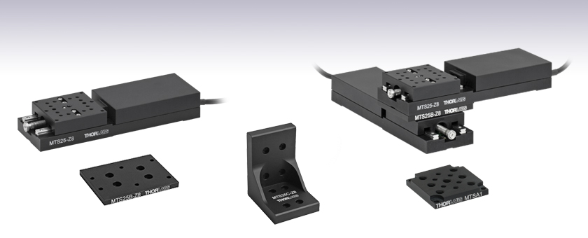
Thorlabs' MTS25-Z8 (MTS25/M-Z8) Motorized Translation Stage provides 25 mm (0.98") of electronically controlled linear travel along a well-defined axis. Each stage is equipped with a 1.50" x 1.50" (37.5 mm x 37.5 mm) tapped hole matrix that includes eighteen 4-40 (M3) taps and a centered 8-32 (M4) tap. By integrating the moving platform with the actuator, the overall package size is greatly reduced relative to standard motorized stages like the PT1-Z8 Motorized Stage.
The moving platform contains holes for alignment pins that ensure orthogonality when the stage is stacked with other stages or connected to our accessories. Horizontal loads of 25 lbs (12 kg) and vertical loads of 10 lbs (4.5 kg) are supported by the 67:1 planetary gear head. A built-in Hall Effect encoder provides a resolution of 29 nm (see the Specs tab for additional details).
The translation mechanism, based upon a dual set of linear rails with continuously recirculating ball bearings, provides smooth, low-friction movement. Built-in limit switches prevent travel outside of the intended range, regardless of the control interface being used.
Mounting Adapters and Stage Combinations
Thorlabs' adapter plates and brackets provide a convenient way to mount the MTS25-Z8 on an optical table or breadboard; to install a motor along the optical axis of our 60 mm cage systems; and to allow several stages to be combined in XY, XZ, or XYZ configurations. A multi-hole adapter plate is also available that offers seven 1/4"-20 (M6) and six 8-32 (M4) tapped holes, providing more options when mounting standard optical accessories to the top platform. Our MTS50-Z8 50 mm (1.97") Motorized Translation Stage can be also be combined with the MTS25-Z8 in certain arrangements. All of these options are described in greater detail below.
Controller Options
The KDC101 DC Servo Motor Controller and a 15 V power supply, sold separately below, are required to operate these stages. Alternatively, we offer the KMTS25E bundle, which includes the MTS25-Z8 translation stage, the KDC101 DC Servo controller, and a KPS101 power supply at a significant savings over ordering these items separately.
The KDC101 provides control for a single axis, with or without a PC. It is bundled with Thorlabs' Kinesis® software, which supplies out-of-the-box stage control from a PC and enables support for common programming interfaces like LabVIEW and LabWindows. A USB cable is included with the KDC101.
Thorlabs also manufactures the PT1-Z8 Motorized Translation Stage, which features a larger mounting surface for even more flexibility.
| Motor Specifications | |
|---|---|
| Motor Type | DC Servo |
| Nominal Voltage | 6 V |
| No Load Speed | 6560 rpm |
| No Load Current | 7.43 mA |
| Nominal Speed | 1050 rpm |
| Nominal Torque (Maximum Continuous Torque) | 1.26 mN•m |
| Nominal Current (Maximum Continuous Current) | 0.156 A |
| Stall Torque | 1.54 mN•m |
| Starting Current | 0.184 A |
| Maximum Efficiency | 65% |
| Terminal Resistance | 32.7 Ω |
| Terminal Inductance | 0.607 mH |
| Torque Constant | 8.38 mN•m/A |
| Speed Constant | 1140 rpm/V |
| Speed / Torque Gradient | 4450 rpm/mN•m |
| Mechanical Time Constant | 13.9 ms |
| Rotor Inertia | 0.298 g•cm2 |
| Feedback | Hall Effect Encoder |
| Stage Specifications | |
|---|---|
| Translation | |
| Travel Range | 25 mm (0.98") |
| Bidirectional Repeatabilitya | 1.6 µm |
| Backlashb | <6 µm |
| Min Achievable Incremental Movementc | 0.05 µm |
| Min Repeatable Incremental Movementd | 0.8 µm |
| Home Location Accuracy | ±4.0 µm |
| Resolution | 29 nm (See Calculation Below) |
| Motion Parameters | |
| Velocity (Max) | 2.4 mm/s |
| Velocity Stability | ±0.25 mm/s |
| Acceleration (Max) | 4.5 mm/s2 |
| Load Capacity | |
| Vertical Load | Recommended:e <4.0 kg (<8.8 lbs) Max: 4.5 kg (10 lbs) |
| Horizontal Load | Recommended:e <10 kg (<22 lbs) Max: 12 kg (25 lbs) |
| Straightness | |
| Pitch | <0.04° (<698 µrad) |
| Yaw | <0.05° (<872 µrad) |
| Absolute On-Axis Accuracy | 145 µm |
| Percentage Accuracy (Max) | 0.3% |
| Physical | |
| Dimensions | 5.31" x 1.69" x 0.87" (134.9 mm x 42.9 mm x 22.1 mm) |
| Weight | 0.31 kg (0.68 lb) |
| Cable Length | 0.5 m (1.6 ft) |
Resolution Calculation
For the MTS25-Z8 (MTS25/M-Z8), there are 512 encoder counts per revolution of the motor. The output shaft of the motor goes into a 67:1 planetary gear head. This requires the motor to rotate 67 times to rotate the 1.0 mm pitch lead screw one revolution. The end result is the lead screw advances by 1.0 mm.
The linear displacement of the actuator per encoder count is given by
512 x 67 = 34,304 encoder counts per revolution of the lead screw,
whereas the linear displacement of the lead screw per encoder count is given by
1.0 mm / 34,304 counts = 2.9 x 10⁻⁵ mm (29 nm).
Motor Connector
D-Type Male

| Pin | Description | Pin | Description |
|---|---|---|---|
| 1 | Ground/Return | 9 | Ident |
| 2 | Forward Limit Switch | 10 | Vcc |
| 3 | Reverse Limit Switch | 11 | Encoder A |
| 4 | Reserved for Future Use | 12 | Reserved for Future Use |
| 5 | Motor - | 13 | Encoder B |
| 6 | Reserved for Future Use | 14 | Reserved for Future Use |
| 7 | Motor + | 15 | Reserved for Future Use |
| 8 | Reserved for Future Use |
Thorlabs offers two platforms to drive our wide range of motion controllers: our Kinesis® software package or the legacy APT™ (Advanced Positioning Technology) software package. Either package can be used to control devices in the Kinesis family, which covers a wide range of motion controllers ranging from small, low-powered, single-channel drivers (such as the K-Cubes™ and T-Cubes™) to high-power, multi-channel, modular 19" rack nanopositioning systems (the APT Rack System).
The Kinesis Software features .NET controls which can be used by 3rd party developers working in the latest C#, Visual Basic, LabVIEW™, or any .NET compatible languages to create custom applications. Low-level DLL libraries are included for applications not expected to use the .NET framework. A Central Sequence Manager supports integration and synchronization of all Thorlabs motion control hardware.

Kinesis GUI Screen

APT GUI Screen
Our legacy APT System Software platform offers ActiveX-based controls which can be used by 3rd party developers working on C#, Visual Basic, LabVIEW™, or any Active-X compatible languages to create custom applications and includes a simulator mode to assist in developing custom applications without requiring hardware.
By providing these common software platforms, Thorlabs has ensured that users can easily mix and match any of the Kinesis and APT controllers in a single application, while only having to learn a single set of software tools. In this way, it is perfectly feasible to combine any of the controllers from single-axis to multi-axis systems and control all from a single, PC-based unified software interface.
The software packages allow two methods of usage: graphical user interface (GUI) utilities for direct interaction with and control of the controllers 'out of the box', and a set of programming interfaces that allow custom-integrated positioning and alignment solutions to be easily programmed in the development language of choice.
A range of video tutorials is available to help explain our APT system software. These tutorials provide an overview of the software and the APT Config utility. Additionally, a tutorial video is available to explain how to select simulator mode within the software, which allows the user to experiment with the software without a controller connected. Please select the APT Tutorials tab above to view these videos.
Software
Kinesis Version 1.14.25
The Kinesis Software Package, which includes a GUI for control of Thorlabs' Kinesis and APT™ system controllers.
Also Available:
- Communications Protocol
Software
APT Version 3.21.4
The APT Software Package, which includes a GUI for control of Thorlabs' APT™ and Kinesis system controllers.
Also Available:
- Communications Protocol
These videos illustrate some of the basics of using the APT System Software from both a non-programming and a programming point of view. There are videos that illustrate usage of the supplied APT utilities that allow immediate control of the APT controllers out of the box. There are also a number of videos that explain the basics of programming custom software applications using Visual Basic, LabView and Visual C++. Watch the videos now to see what we mean.
 |
Click here to view the video tutorial | |
To further assist programmers, a guide to programming the APT software in LabView is also available.
 |
Click here to view the LabView guide | |
| Posted Comments: | |
Jean-Baptiste Le Bouquin
(posted 2020-09-12 04:44:12.79) Hello, what is the operational ambiant temperature for the MTS25/M-Z8. We consider a use case in a telescope where ambiant temperature can vary from 5degC to 20degC. Thanks. DJayasuriya
(posted 2020-09-14 09:21:43.0) Thank you for inquiry. The unit would be functional within the temperature range 5 deg C to 40 deg C. Please note that if the unit has been stored at a low temperature or in an environment of high humidity,
it must be allowed to reach ambient conditions before being powered up. Hope this helps. Jean-Baptiste Le Bouquin
(posted 2019-10-14 14:31:05.527) Hi, How is it possible to control the KMTS25E with a Linux computer ? Ideally we need to control the translation stage with a serial communication. Thanks, Jean-Baptiste rmiron
(posted 2019-10-15 06:17:42.0) Response from Radu at Thorlabs: Hello, Jean-Baptiste. That is possible. You will need to refer to the serial protocol's documentation, which can be found here: https://www.thorlabs.com/Software/Motion%20Control/APT_Communications_Protocol.pdf
If have an RS-232 port on your PC, you can simply connect to the KDC101 controller via an RS-232 to USB cable. If not, you can set the relevant USB port as a virtual communications port. In order to do so, access DeviceManager, identify "APT USB Device" under "Universal Serial Bus controllers", right-click on it, go to Properties\Advanced and tick "Load VCP". If you now power-cycle the device, you should see a new port appear under "Ports".
Having done this, you should set the port settings as described on page 29 of the documentation. The device to real unit conversion ratios can be found on page 35. On pages 8-9 you can find the list of serial commands that you can send to your controller. If you require further assistance, please contact your local technical support team, who will gladly help. dale.durand
(posted 2016-11-30 15:25:52.397) I am using an MTS25-Z8 linear stage and TDC001 controller from LabView. It is working and I can command the stage to absolute positions. Where can I get descriptions of the move parameters; fMinVel, fAccn, and fMaxVel? It seems fMaxVel is the maximum velocity in mm per second. Why is there a minimum velocity? Are the units for fAccn mm/sec^2?
Thank you,
Dale Durand bhallewell
(posted 2016-12-07 04:42:13.0) Response from Ben at Thorlabs: When using APT, these parameters are set for real world units, in your case mm/sec & mm/sec^2. A description of these parameters can be found in the Motor Control Methods section of the APTServer help file & copied here. These are limited by the values we spec in the stage manual & on the website.
fMinVel - the minimum velocity at which to start and end a move (which we define as 0 in all cases).
fAccn - the rate at which the velocity climbs from minimum to maximum
slows from maximum to minimum.
fMaxVel - the maximum velocity at which to perform a move.
For Kinesis, this depends upon which method was used to set the velocity parameters of your device setup. In the .NET_API help file, we reference SetMoveRelativeDistance_DeviceUnit & SetMoveRelativeDistance, which enables the user to set velocities based on device encoder units (as defined in our communication protocol) & real world units respectively. stone4
(posted 2015-01-12 11:24:13.407) The TDC001 single cube PS has a plug on the bottom side. There is no reference to this in the manual. Can you provide details as to the function and use of this port? Also, how far can the TDC001 and Control computer be spaced? Can the system use a USB - RJ45 ethernet bride to position them farther than a powered USB extender? Thanks for your help. Cheers G Stone - stone4@llnl.gov msoulby
(posted 2015-01-13 11:14:22.0) Response from Mike at Thorlabs: The port on the bottom of the TDC001 is for when it is used with our TCH002 T-cube control hub. Up to six cube can all be powered on the hub without the need for additional USB or power cables. If using the T-cube as a standalone item then we would recommend not using a USB cable that is any longer than a couple of meters to avoid any communication problems with the PC. However if you do need to extend the cable then we would recommend using a powered USB hub to do this. dodge.charger.r.t.69
(posted 2014-03-04 21:46:15.517) I am controlling a MTS25/M-Z8E stage via LabView and noticed the reverse movement specified by a displacement of say 10um from 2000um overshoots the desired mark(1990um) by a random value (say 50um thus reaching 1940um)and then the stage travels forward again to the 1990um mark. How can i rectify it? Solution would be of really great help. Thanks msoulby
(posted 2014-03-06 10:05:39.0) Response from Mike at Thorlabs: This extra movement is caused by the backlash correction setting; this backlash correction is designed to make sure that all positions are approached from one direction which has the effect of improving the overall repeatability of the stage. The default correction amount for the MTS25/M-Z8E is 0.050mm (50um) which matches the effect you are observing. To remove backlash correction you can simply set this setting to ZERO in either the APT user settings or by calling the ActiveX method SetBLashDist. twizypivo89
(posted 2014-01-08 21:52:36.917) I am planning to purchase a MTS25/M-Z8 stage and to know if the product would be suitable for me, I would like to know the minimum achievable speed of movement of the stage (linear speed of the stage). Thanks. msoulby
(posted 2014-01-09 06:16:06.0) Response from Mike at Thorlabs: The minimum velocity value you can enter for the MTS50-Z8 is limited by the APT software code, so the smallest value you can enter and still get movement is the minimum velocity, which is about 40um/s. Also at these velocities the velocity may not be as stable as at higher velocities and the motion be jumpy and not smooth. If you need high resolution sub-micron positioning you would get better results using a piezo actuated stage or a direct drive linear stage such as the DDS220/M. hadi.abidin
(posted 2013-04-22 12:40:00.75) How will this linear stage perform when mounted vertically under low vacuum(100mbar). Can you provide a quotation for a vacuum version of this stage tcohen
(posted 2013-04-25 11:09:00.0) Response from Tim at Thorlabs: The stage itself should be fine for this low vacuum. The motor, however, would likely require adding vacuum compatible greases. We will contact you with a quotation. jlow
(posted 2012-12-27 11:11:38.363) Response from Jeremy at Thorlabs: It could be that the velocity and acceleration settings are set too low. I will get in contact with you directly to discuss about this. ggjmlee
(posted 2012-12-26 18:54:28.867) I bought two MTS25/M-Z8s' with controllers. When I bought them, they moved fast. But moving speed of them has slowed down now. Could you let me know any possible causes and how to solve this problem? I like to move the stage faster as when I bought them.
Thanks tcohen
(posted 2012-06-13 09:16:00.0) Response from Tim at Thorlabs: Thank you for your feedback! I will contact you directly to discuss your measurements and operating conditions to determine the performance of your stage and provide support. aboudreault
(posted 2012-06-07 15:30:53.0) Hello, recently we have bought two motorized stages, a MTS25 and a MTS50. The MTS25 respect the spec for bidirectional repeatability and home location accuracy but the MTS50 is less good. Instead to have bidirectional of 1.6um it is more like 5 or 6um and the home location accuracy is around 25um. Do you have an idea why my MTS50 is less good. bdada
(posted 2011-07-18 12:07:00.0) Response from Buki at Thorlabs:
Our motion control products use APT software, which use ActiveX control for various programming environments such as LabVIEW. We have some tutorials online available to help you get started. You can find them at:
http://www.thorlabs.de/images/TabImages/GuideToLabVIEWandAPT.pdf
http://www.thorlabs.de/tutorials/Intro.cfm
You can also download the APT software package at http://www.thorlabs.de/software_pages/ViewSoftwarePage.cfm?Code=APT and run it in simulation mode to get familiar with the software.
Please contact TechSupport@thorlabs.com if you have further questions luis.ferreira
(posted 2011-07-15 17:12:58.0) Is it possible to provide LabView Drivers for these translators ? bdada
(posted 2011-04-26 12:00:00.0) Response from Buki at Thorlabs:
Thank you for your feedback. A position error of 3mm is much higher than normal. We will contact you directly to get your serial number. In the meantime, please check that you have set up the APT config programme to the correct stage type. sema
(posted 2011-04-26 05:33:37.0) I am using the MTS25 with a t-cube controller. For a 10 mm step entered in the software, I get approx. 7 mm actual translation. Can that be corrected with a calibration file? If so, can I do the calibraiton myself, or where do I get such a file? |
Motorized Linear Translation Stages
Thorlabs' motorized linear translation stages are offered in a range of maximum travel distances, from a stage with 20 µm of piezo translation to our 600 mm direct drive stage. Many of these stages can be assembled in multi-axis configurations, providing XY or XYZ translation. For fiber coupling applications, please see our multi-axis stages, which offer finer adjustment than our standard motorized translation stages. In addition to motorized linear translation stages, we offer motorized rotation stages, pitch and yaw platforms, and goniometers. We also offer manual translation stages.
Piezo Stages
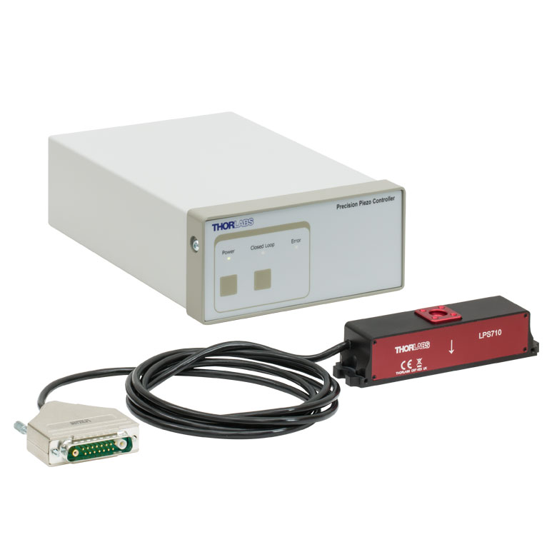
These stages incorporate piezoelectric elements in a variety of drive mechanisms. Our Nanoflex™ translation stages use standard piezo chips along with manual actuators. Our LPS710E z-axis stage features a mechanically amplified piezo design and includes a matched controller. The PD1 stage incorporates a piezo inertia drive that uses "stick-slip" friction properties to obtain an extended travel range. The Elliptec™ stages use resonant piezo motors to push and pull the moving platform through resonant elliptical motion.
| Piezoelectric Stages | ||||||
|---|---|---|---|---|---|---|
| Product Family | Nanoflex™ 20 µm Stage with 5 mm Actuator |
Nanoflex™ 25 µm Stage with 1.5 mm Actuator |
LPS710E 1.1 mm Z-Axis Stage |
PD1 20 mm Stage | Elliptec™ 28 mm Stage | Elliptec™ 60 mm Stage |
| Click Photo to Enlarge |
 |
 |
 |
 |
 |
 |
| Travel | 20 µm + 5 mm Manual | 25 µm + 1.5 mm Manual | 1.1 mm | 20 mm | 28 mm | 60.0 mm |
| Maximum Velocity | - | - | 3 mm/s | 180 mm/s | 90 mm/s | |
| Drive Type | Piezo with Manual Actuator | Amplified Piezo | Piezoelectric Inertia Drive | Resonant Piezoelectric Motor | ||
| Possible Axis Configurations |
X, XY, XYZ | - | X, XY, XYZ | X | ||
| Additional Details | ||||||
Stepper Motor Stages
These translation stages feature removable or integrated stepper motors and long travel ranges up to 300 mm. The MLJ150 stage also offers high load capacity vertical translation. The other stages can be assembled into multi-axis configurations.
| Stepper Motor Stages | |||||||
|---|---|---|---|---|---|---|---|
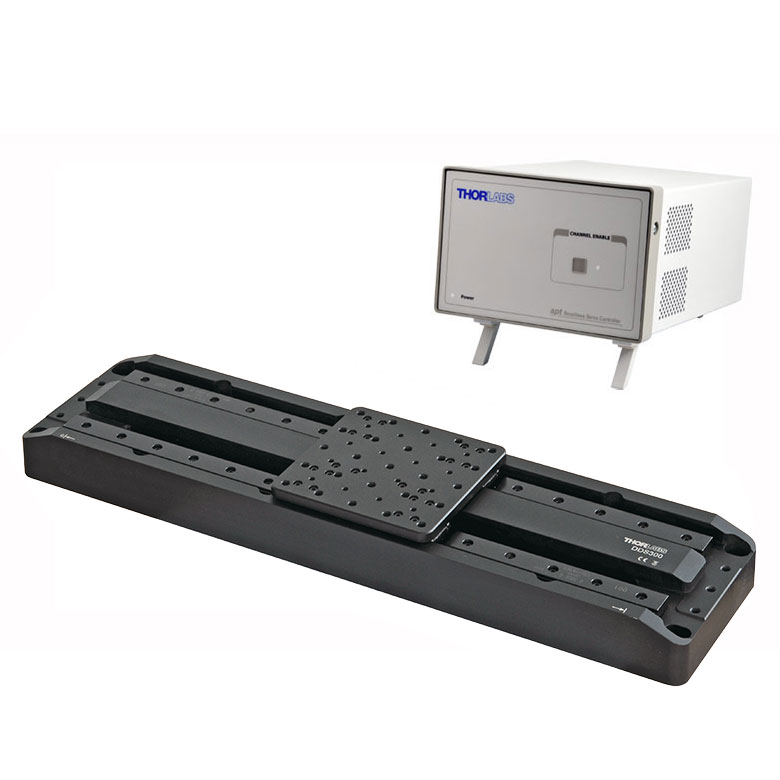
| Product Family | LNR Series 25 mm Stage |
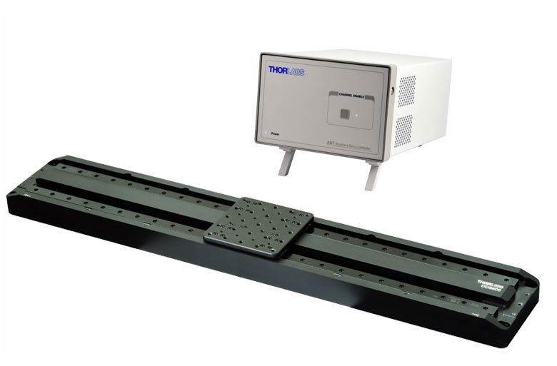
LNR Series 50 mm Stage |
MLJ150 50 mm Vertical Stage |
NRT Series 100 mm Stage |
NRT Series 150 mm Stage |
LTS Series 150 mm Stage |
LTS Series 300 mm Stage |
| Click Photo to Enlarge |
 |
 |
 |
 |
 |
 |
 |
| Travel | 25 mm | 50 mm | 50 mm | 100 mm | 150 mm | 150 mm | 300 mm |
| Maximum Velocity | 2.0 mm/s | 50 mm/s | 3.0 mm/s | 30 mm/s | 50 mm/s | ||
| Possible Axis Configurations |
X, XY, XYZ | X, XY, XYZ | - | X, XY, XYZ | X, XY, XYZ | ||
| Additional Details | |||||||
DC Servo Motor Stages
Thorlabs offers linear translation stages with removable or integrated DC servo motors. These stages feature low profiles and can be assembled in multi-axis configurations.
| DC Servo Motor Stages | |||||
|---|---|---|---|---|---|
| Product Family | MT Series 12 mm Stages | PT Series 25 mm Stages | MTS Series 25 mm Stage | MTS Series 50 mm Stage | KVS30 30 mm Vertical Stage |
| Click Photo to Enlarge |  |
 |
 |
 |
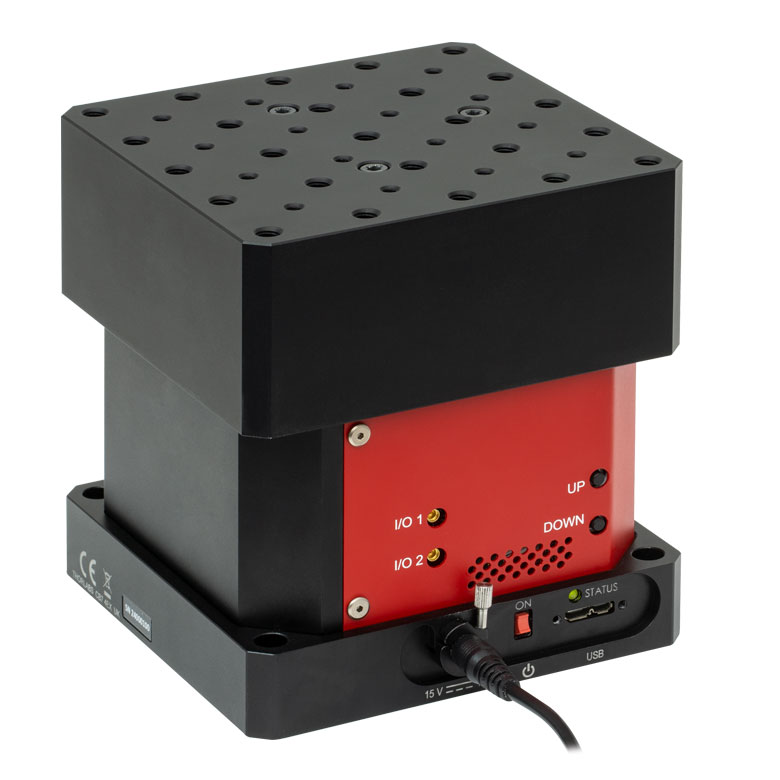 |
| Travel | 12 mm | 25 mm | 25 mm | 50 mm | 30 mm |
| Maximum Velocity | 2.6 mm/s | 2.4 mm/s | 8.0 mm/s | ||
| Possible Axis Configurations | X, XY, XYZ | X, XY, XYZ | - | ||
| Additional Details | |||||
Direct Drive Stages
These low-profile stages feature integrated brushless DC servo motors for high speed translation with zero backlash. When no power is applied, the platforms of these stages have very little inertia and are virtually free running. Hence these stages may not be suitable for applications where the stage's platform needs to remain in a set position when the power is off. We do not recommend mounting these stages vertically.
| Direct Drive Stages | |||
|---|---|---|---|
| Product Family | DDS Series 220 mm Stage |
DDS Series 300 mm Stage |
DDS Series 600 mm Stage |
| Click Photo to Enlarge |  |
 |
 |
| Travel | 220 mm | 300 mm | 600 mm |
| Maximum Velocity | 300 mm/s | 400 mm/s | 400 mm/s |
| Possible Axis Configurations | X, XY | X | X |
| Additional Details | |||
 Low-Profile Motorized Translation Stage")
 Zoom
Zoom Click to Enlarge
Schematic of Metric Version
 Click to Enlarge
Schematic of Imperial Version
- Built-In 25 mm (0.98") DC Servo Actuator
- Includes One 8-32 (M4) and Eighteen 4-40 (M3) Tapped Holes
- Bundles Available with KDC101 Controller and KPS101 Power Supply
- Multi-Axis, Breadboard, and 60 mm Cage System Mounting Adapters Offered Below
Thorlabs' MTS25-Z8 (MTS25/M-Z8) Motorized Translation Stage provides linear motion in one dimension. One centered 8-32 (M4) tapped hole and eighteen 4-40 (M3) tapped holes allow small optomechanics to be directly mounted to the moving platform. Based upon a dual set of linear rails with continuously recirculating ball bearings, the translation mechanism provides smooth, low-friction movement.
The stage requires a standalone controller unit and power supply. For this purpose, we recommend our KDC101 K-Cube™ Motor Controller and Power Supply, which are described in more detail below. For convenience, we offer a stage, KDC101 DC Servo controller, and KPS101 power supply in a bundle at a significant savings over purchasing these items individually. The power supply you receive will be compatible with outlets in your region. Please contact Tech Support prior to ordering if you require a different plug.
The motor cable that is built into the stage is 0.5 m (1.64 ft) long. If more length is required for your application, we recommend our PAA632 Extension Cable, which provides an additional 2.5 m (8.20 ft). It is sold at the bottom of this page.

 Zoom
Zoom
- Mount an MTS25-Z8 Stage to a Breadboard or Optical Table
- Contains Four 1/4" (M6) Counterbored Slots for Imperial and Metric Compatibility
- Includes All Necessary Mounting Hardware and Alignment Pins for Parallelism
The MTS25A-Z8 Base Plate contains four 1/4" (M6) counterbored slots that allow an attached MTS25-Z8 (MTS25/M-Z8) to be positioned on a breadboard, as shown in the photo to the right. The bottom of the translation stage is connected to the base plate using four 4-40 or M3 cap screws. Two alignment pins ensure that the translation axis is parallel to the length of the plate.

 Zoom
Zoom
- Mount Standard Optical Accessories
- Contains Seven 1/4"-20 (M6) and Six 8-32 (M4) Mounting Holes
- Includes All Necessary Mounting Hardware
The MTSA1(/M) adapter plate fixes to the top platform of the MTS25 stages via the through holes in each corner and 4 screws (supplied). It has an array of seven 1/4"-20 (M6) and six 8-32 (M4) mounting holes to offer increased mounting options when used with general-purpose accessories and components. The working height of the stage with an adapter plate and base plate fitted is 1.4" (35.5 mm). The plate is finished in a black, low reflective anodized coating.

 Zoom
Zoom
- Stack Two MTS25-Z8 Stages in an XY Configuration
- Includes All Necessary Mounting Hardware and Alignment Pins for Orthogonality
The MTS25B-Z8 XY Adapter Plate is designed to orient two MTS25-Z8 (MTS25/M-Z8) stages orthogonally in the XY plane, as shown in the photo to the right. This plate may also be used to stack our 50 mm (1.97") MTS50-Z8 stage with a 25 mm (0.98") MTS25-Z8 stage, but the MTS50-Z8 must be on the bottom.
To begin the assembly process, fasten the plate to the top of the lower stage using four of the provided 4-40 or M3 cap screws. Then insert the provided alignment pins. To complete the assembly, use the remaining 4-40 or M3 cap screws to fasten the plate to the bottom of the upper stage.
In order to mount an MTS25-Z8 stage in the vertical plane, please see the MTS25C-Z8 Right-Angle Bracket shown below.

 Zoom
Zoom Click to Enlarge
Two MTS25-Z8 Stages Stacked in an XZ Configuration Using an MTS25C-Z8 Right-Angle Bracket
- Vertically Mount an MTS25-Z8 Translation Stage
- Designed for XZ or XYZ Configurations
- Includes All Necessary Mounting Hardware and Alignment Pins for Orthogonality
The MTS25C-Z8 Right-Angle Bracket orients an MTS25-Z8 (MTS25/M-Z8) stage along the vertical axis. It is needed when configuring multiple MTS25-Z8 stages into XZ or XYZ arrangements. This bracket may also be used to stack our 50 mm (1.97") MTS50-Z8 stage with a 25 mm (0.98") MTS25-Z8 stage, but the vertical stage must be an MTS25-Z8.
To create the XZ configuration shown to the right, insert two of the provided alignment pins into the horizontal stage. Then fasten the bracket to the top of the horizontal stage using four of the provided 4-40 or M3 cap screws. Next, insert the two remaining alignment pins into the vertical mounting surface. Finally, attach the bracket to the vertical stage with the remaining cap screws.
For XYZ configurations, follow the steps in the previous paragraph, but attach the stage and bracket to an existing XY configuration instead.

 Zoom
Zoom Click to Enlarge
KCH601 USB Controller Hub (Sold Separately) with Installed K-Cube and T-Cube™ Modules (T-Cubes Require the KAP101 Adapter)
Click to Enlarge
KCH601 USB Controller Hub (Sold Separately) with Installed K-Cube and T-Cube™ Modules (T-Cubes Require the KAP101 Adapter)- Front Panel Velocity Wheel and Digital Display for Controlling Motorized Stages or Actuators
- Two Bidirectional Trigger Ports to Read or Control External Equipment
- Interfaces with Computer Using Included USB Cable
- Fully Compatible with Kinesis® or APT™ Software Packages
- Compact Footprint: 60.0 mm x 60.0 mm x 49.2 mm (2.42" x 2.42" x 1.94")
- Power Supply Not Included (See Below)
Thorlabs' KDC101 K-Cube Brushed DC Motor Controller provides local and computerized control of a single motor axis. It features a top-mounted control panel with a velocity wheel that supports four-speed bidirectional control with forward and reverse jogging as well as position presets. A backlit digital display is also included that can have the backlit dimmed or turned off using the top-panel menu options. The front of the unit contains two bidirectional trigger ports that can be used to read a 5 V external logic signal or output a 5 V logic signal to control external equipment. Each port can be independently configured.
The unit is fully compatible with our new Kinesis software package and our legacy APT control software. Please see the Motion Control Software tab for more information.
Please note that this controller does not ship with a power supply. Compatible power supplies are listed below. Additional information can be found on the main KDC101 DC Servo Motor Controller page.

 Zoom
Zoom
Click for Details
A location-specific adapter is shipped with the power supply unit based on your location. The adapters for the KPS101 are shown here.

Click to Enlarge
The KPS101 Power Supply Unit
- Individual Power Supply
- KPS101: For K-Cubes™ or T-Cubes™ with 3.5 mm Jacks
- USB Controller Hubs Provide Power and Communications
- KCH301: For up to Three K-Cubes or T-Cubes
- KCH601: For up to Six K-Cubes or T-Cubes
The KPS101 power supply outputs +15 VDC at up to 2.4 A and can power a single K-Cube or T-Cube with a 3.5 mm jack. It plugs into a standard wall outlet.
The KCH301 and KCH601 USB Controller Hubs each consist of two parts: the hub, which can support up to three (KCH301) or six (KCH601) K-Cubes or T-Cubes, and a power supply that plugs into a standard wall outlet. The hub draws a maximum current of 10 A; please verify that the cubes being used do not require a total current of more than 10 A. In addition, the hub provides USB connectivity to any docked K-Cube or T-Cube through a single USB connection.
For more information on the USB Controller Hubs, see the full web presentation.

 Zoom
ZoomThe PAA632 Extension Cable provides an additional 2.5 m (8.20 ft) of cable length for the 15-pin D-type connectors used throughout our motorized actuator selection. The male end connects to the controller, while the female end connects to the motor.