 Products Home
Solis® LED Driver

- Plug-and-Play Driver for Thorlabs’ Solis® LEDs
- Supports Modulation up to 1 kHz via External TTL Signal
- Automatically Sets Current Limit to Protect the LED
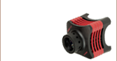
DC20
Top View
DC20
Solis High-Power LED for Microscopy
The DC20 is designed to provide easy plug-and-play operation for Thorlabs’
Solis LEDs.


Please Wait
| DC20 Key Specificationsa | |
|---|---|
| LED Current (Max)b | 1 to 10 A |
| LED Forward Voltage (Max)b | 5.0 to 14.0 V |
| LED Current Limit Accuracy | ±(1% + 25 mA) |
| TTL Modulation Frequency | DC to 1 kHz |
| Modulation Waveform | Square Wave / PWM |

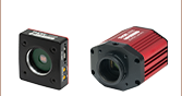
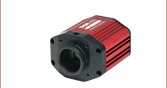
Click to Enlarge
DC20 Solis® LED Driver
| Compatible Thorlabs LEDs | |
|---|---|
| Photo (Click for Link) |
 |
| Description | High-Power Solis LEDs |
Features
- Designed for Thorlabs' Solis® LEDs for Microscopy
- Easily Control LED Intensity Using the Dial
- Protects LED from Overdriving by Automatically Setting the Current Limit
- Provides Drive Current up to 10 A
- Supports LED Forward Voltage up to 14 V
- Accepts External TTL Modulation Signal via BNC Connector
Thorlabs' DC20 Driver is designed to provide a simple way to control any of Thorlabs' Solis LEDs. Easy to set up and use, this driver is an ideal solution for users of our Solis LEDs who don't require the more advanced functions provided by the DC2200 Touchscreen LED Driver. See the Solis LED Drivers tab for a comparison between the DC20 and the DC2200 drivers.
The current provided to the LED is controlled by turning the knob on the top of the driver. The position on the top panel marked LIMIT will correspond to the maximum LED current for the connected Solis LED, as the driver automatically detects and sets the current limit to the value stored in each Solis LED's internal memory to protect it from being overdriven. Pushing on the knob will either switch the LED on at the percentage of the maximum current indicated by the control knob position or turn it off. Alternatively, the LED can be modulated using an external TTL signal connected to a BNC input on the back of the driver's housing. See the Specs tab for the TTL signal requirements.
A tri-color LED on the side of the unit indicates the current LED status, including whether the LED is on or off (useful with IR LEDs), whether the LED is operating normally, or if an error has occurred.
Please note that the DC20 driver is designed specifically to work with the internal electronics in Thorlabs' Solis LEDs and should not be used to drive any other type of LED.
Thorlabs also offers other LEDs drivers that are compatible with our mounted, collimated, fiber-coupled, and PCB-mounted LEDs. See the table below for available LED driver options.
| LED Controller Selection Guide | |||||
|---|---|---|---|---|---|
| Type | Max Number of LEDs | Max Current | Modulation Mode | USB | Compatible LEDs |
| Compact T-Cube™ Driver | 1 | 1.2 A | 0 - 5 kHz | No | Mounted, Collimated, Fiber Coupled, and PCB Mounteda |
| 4-Channel Driver | 4 | 1 A | 0 - 100 kHz | Yes | |
| Solis® LED Driver | 1 | 10 A | 0 - 1 kHz | No | High Power |
| High-Power Touchscreen Driver | 1 | 10.0 A | 0 - 250 kHz | Yes | High Power , Mounted, Collimated, Fiber Coupled, and PCB Mounteda |
| DC20 Specifications | |
|---|---|
| Constant Current Mode (CW) | |
| LED Current (Max)a | 1 to 10 A |
| LED Forward Voltage (Max)a | 5.0 to 14.0 V |
| LED Current Limit Accuracy | ±(1% + 25 mA) |
| Noise and Ripple (1 Hz to 10 MHz, RMS) | <400 µA (Typical) |
| TTL Modulation Modeb | |
| Input Impedance | 10 kΩ |
| Modulation Frequency Range | DC to 1 kHz |
| Duty Cycle Range | 0.2% to 99.8% (10 Hz) 2.0% to 98.0% (100 Hz) 20% to 80% (1 kHz) |
| Modulation Waveform | Square Wave / PWM (Pulse Width Modulation) |
| TTL Low Voltage Level | 0.0 V to 0.8 V |
| TTL High Voltage Level | 2.0 V to 5.0 V |
| General | |
| Power Supply | 15 V DC |
| Power Consumption | 65 VA (Max) |
| Operating Temperature Rangec | 0 to 40 °C |
| Storage Temperature Range | -40 to 70 °C |
| Dimensions | 85.4 mm x 59.6 mm x 100.0 mm (3.36" x 2.35" x 3.94") |
| Weight | 215 g (without Power Supply) 490 g (with Power Supply) |
| Callout | Description |
|---|---|
| 1 | Control Knob: Turn for LED Current Adjustment, Push to Turn LED On and Off |
| 2 | BNC Jack for TTL Modulation Input: Low Voltage Level: 0.0 V to 0.8 V, High Voltage Level: 2.0 V to 5.0 V |
| 3 | Solis® LED Connector |
| 4 | Input for Power Supply |
| 5 | Status LED Orange: DC20 Ready for Operation, LED Off Green: Solis LED On Red or Blinking: Warning Indicatora |

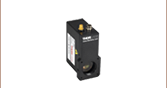
Click to Enlarge
Connectors and Control Knob on the DC20

Click to Enlarge
Status Indicator LED

Click to Enlarge
DC20 Top View
DC20 Connector Pin Diagrams
Solis® LED Connector
12 Pin Neutrik MiniCON Female Connector

The DC20 Driver is only intended for use with Thorlabs' Solis LEDs, so this pin diagram is provided for reference only.
| Pin | Connection | Pin | Connection |
|---|---|---|---|
| 1 | LED Cathode | 7 | LED Anode |
| 2 | LED Cathode | 8 | LED Cathode |
| 3 | Not Used | 9 | LED Cathode |
| 4 | LED Anode | 10 | Not Used |
| 5 | LED Anode | 11 | EEPROM (Data) I/O |
| 6 | LED Anode | 12 | EEPROM (Data) Ground |
External Trigger
BNC Jack for TTL Signal

Low Voltage: 0.0 to 0.8 V
High Voltage: 2.0 to 5.0 V

The following items are included in the DC20 package:
- DC20 LED Current Controller
- Power Supply
- Location-Specific Power Cord
| Posted Comments: | |
| No Comments Posted |
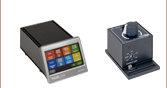
Thorlabs offers two options for driving our Solis® LEDs. The DC20 is a basic option that allows users to control the intensity of their LED using a control knob on the top or via an external TTL signal for modulation. For more advanced applications, our DC2200 drivers provides a touchscreen interface that allows users to control the LED current, select internal or external modulation modes, and more. The table below provides a comparison of key controller features.
| Solis® LED Driver Selection Guide | ||
|---|---|---|
| Item # | DC20 | DC2200 |
| Photo (Click to Enlarge) |  |
 |
| LED Current / Forward Voltage (Max) | 1 to 10 A / 5.0 to 14.0 Va | 1.0 A / 50.0 Vb 2.0 A / 35.0 Vb 4.0 A / 15.0 Vb 5.0 A / 10.0 Vb 10.0 A / 5.0 Vb |
| Noise and Ripple (1 Hz to 10 MHz, RMS, Typical) |
<400 µA | <100 µA from 0.0 to 4.0 A <200 µA from 4.0 to 10.0 A |
| Internal Modulation Modes | - | 0.1 Hz to 20 kHz (PWMc Mode) 1 µs to 10 s On or Off Time (Pulse Mode) 20 Hz to 100 kHz (Internal Modulation Mode with Sine, Square, Triangle Waveforms) |
| External Modulation (Arbitrary Waveform) |
- | DC - 250 kHz [Small Signal Bandwidth (Sine)]d |
| TTL Modulation (External) | DC to 1 kHz (Square Wave, PWMc) | DC to ≥18 kHze |
| LED Control Interface | Knob to Control LED Current, BNC Port for TTL Modulation |
Easy-to-Navigate Touchscreen Interface, Brightness and Constant Current Operating Modes, Internal and External Modulation Modes, SMA Port for External Modulation Accepts TTL Signal or Waveform from a Function Generator, USB Interface for Remote Control |
| Current Limit | Automatically Read and Set from the Solis LED's Internal Memory to Protect the LED from Overdriving | |
| External Software Interface | No | DC2200 GUI |
| Other Compatible LEDs | - | Mounted Collimated Fiber Coupled MCPCB Mountedf |