 Products Home / Optical Power and Energy Meters / Digital Handheld Optical Power and Energy Meter Console
Digital Handheld Optical Power and Energy Meter Console
- Power and Energy Measurements for Free Space and Fiber Applications
- Designed for High Accuracy, Reliability, and Ease of Use
- Over 25 Compatible Sensors
PM100D
Multiple Display
Options
Photodiode, Fiber, Integrating
Sphere, Thermal, and Pyroelectric
Sensors Available
Detector Options


Please Wait
| Item # | PM100D |
|---|---|
| Compatible Sensors | Photodiode, Thermal, and Pyroelectric |
| Optical Power Rangea | 100 pW to 200 W |
| Optical Energy Rangea | 3 µJ to 15 J |
| Available Sensor Wavelength Rangea | 185 nm - 25 μm |
| Display Refresh Rate | 20 Hz |
| Bandwidtha | DC - 100 kHz |
| Photodiode Sensor Rangeb | 50 nA - 5 mA |
| Thermopile Sensor Rangeb | 1 mV - 1 V |
| Pyroelectric Sensor Rangeb | 100 mV - 100 V |
| Power Meter Selection Guide |
|---|
| Sensors |
| Photodiode Power Sensors |
| Thermal Power Sensors |
| Thermal Position & Power Sensors |
| Pyroelectric Energy Sensors |
| Power Meter Consoles |
| Digital Handheld Console |
| Analog Handheld Console |
| Touchscreen Handheld Console |
| Dual-Channel Benchtop Console |
| Complete Power Meters |
| Power Meter Bundles |
| Wireless Power Meters with Sensors |
| Compact USB Power Meters |
| Field Power Meters for Terminated Fibers |
| USB Interfaces, External Readout |
Features
- Handheld Digital Power Meter Console
- Designed for Coherent and Incoherent Light Source Measurements
- Power and Energy Measurements for CW and Pulsed Source Detection
- Advanced Measurement Capabilities
- Large 4" LCD Display with Multiple Display Options
- Compatible with Over 25 Sensors (Shown Below)
- Pre-Installed 8 GB SD Memory Card for Storing and Transferring Data
- USB 2.0 Interface
- Long-Life Internal Li-Polymer Battery
- Sensor Upgrade and Recalibration Services Available
- Optical Power Monitor PC Software Available (See Software Tab for Details)
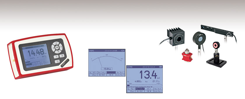
The PM100D is the cornerstone of Thorlabs' optical power and energy meter consoles and is the digital counterpart to the PM100A analog power meter console. The console (and sensor, sold separately) is ideal for use as a CW and pulsed source power meter, incoherent optical source power meter, general light power meter, fiber power meter, and more. The display on the PM100D features adjustable brightness settings, with the option to turn off the backlight completely while still being readable.
The PM100D is compatible with more than 25
This power and energy meter console is also available as a kit, bundled with our most popular sensors. Please visit our power meter kits page for more information. If you have any questions regarding these kits, or would like to suggest other kit options, please contact Tech Support with inquiries.
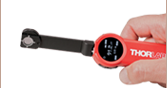
For a touchscreen version of the PM100D with more advanced spectral correction features, inputs for temperature and humidity sensors, data logging, and additional memory, we offer the PM400 capacitive touchscreen power and energy meter console. We also offer wireless, handheld, self-contained power meters, which feature an ultra-slim sensor with a built-in OLED display as well as Bluetooth® and USB features.
Console Design
The compact housing has a large, 4” backlit display with a resolution of 320 x 240 pixels and illuminated buttons, all of which make operation in dark labs easy. The LCD’s clear GUI offers easy data readouts with an intuitive navigation scheme. Interactive tooltips help to operate the device by giving the user step-by-step operating instructions, displaying the next step on the screen.
The PM100D features four standard measurement screens. The first option is a numeric readout useful for standard power and energy readings. The second option is a tuning needle typically seen on analog devices, however, optimized to run as a digital readout on the display screen. Third is a tuning graph, which is very convenient for fine tuning CW and pulsed sources.
The unit can also be run in a data acquisition mode. Simply start the scan and the unit automatically starts recording data such as current power/energy, minimum, maximum, standard deviation, and other important statistics recorded over the acquisition period. The PM100D also features several user customizable displays and audio tuning for use when the detector is not within visual range. See the Display Screens tab for further information.

Click to Enlarge
Thorlabs' C-Series Power Meter Sensor Connectors Include the Sensor Calibration Data
Connectivity
The sensor connector, shown to the left, enables "hot swappable" quick sensor exchange. The sensor connectors contain all the sensor information including NIST-traceable responsivity curves, sensor types, and model number.
A slot for an SD memory card (an 8 GB SD card is pre-installed) allows data recording even in stand-alone operation, giving the user large memory storage when recording data in the field or away from a computer in the lab. Data can also be recorded via the USB PC connection and optical power monitor software. This software is capable of handling up to eight consoles simultaneously. The features of the PC control software are highlighted in the Software tab.
In addition to remote control operation and data logging/recording, the USB connection can also act as the charging system for the Li-Polymer battery. Also included is an AC battery charger which uses an intelligent charging management system to improve battery lifetime and reduce battery memory effects.
Recalibration Service
Recalibration services are available for our thermal and photodiode power sensors, pyroelectric energy sensors, and consoles. We recommend your Thorlabs sensor and console be recalibrated as a pair; however, each may be recalibrated individually. To order this service for your sensor or combined sensor and console, scroll to the bottom of the page and select the appropriate Item # that corresponds to your sensor. To order this service for only your console, please contact Tech Support.
Sensor Upgrade Service
Thorlabs' current line of C-Series sensors and power meter consoles are not compatible with old power meter consoles and sensor heads, respectively. We offer a sensor upgrade service if you want to use your existing sensors with a new power meter console. Note: upgraded sensors will be incompatible with old power meter consoles and new sensors converted to work with older consoles will not be compatible with the PM100D. Please contact our Tech Support team for details.
| Item # | PM100D |
|---|---|
| Display | |
| Display Type | Graphical LCD 320 x 240 pixels, LED Backlight |
| Display Screens | Numerical, Bar Graph, Line Graph, Statistics, Simulated Analog Needle |
| Viewing Area | 81.4 mm x 61.0 mm (3.20" x 2.40") |
| Refresh Rate | 20 Hz |
| Audio | 1x Speaker |
| Sensor Interface | |
| Compatible Sensors | All Photodiodes, Thermopiles, and Pyros See Below for Full Sensor Specs |
| Time Constant Correction | <1 s |
| AD Converter | 16 bit |
| Trigger (Pulse Measurements, Pyroelectric Sensors) | Adjustable, 0.1 - 100% |
| Connector | DB9F, Left Side |
| Sensor Temperature Control | Thermistor |
| Temperature Range | -10 to 80 °C |
| Analog Outputs | |
| Signal | Amplified Input Signal (Not Corrected) |
| Voltage Range | 0 to 2 V |
| Accuracy | ±3% |
| Bandwidth | Up to 100 kHz, Dependent on Sensor and Settings |
| Connector | SMA, Left Side |
| Digital Outputs | |
| Memory | 8 GB Removable SD Card |
| Connector / Interface | Mini USB / USB 2.0 |
| Power | |
| Battery | Li-Polymer, 3.7 V, 1300 mAh |
| Charger / DC Input | 5 V / 1 A |
| Dimensions and Mounting | |
| Dimensions (L x W x H) | 180 mm x 105 mm x 38 mm (7.09" x 4.13" x 1.50") |
| Weight | <0.5 kg (<1.1 lb) |
| Mounting Options | Kickstand; 1/4"-20 Post Thread |
| Operating Temperature> | 0 to 40 °C |
| Storage Temperature | -40 to 70 °C |
Sensor Compatibility Specs
| Item # | PM100D | ||
|---|---|---|---|
| Detector Compatibility | Photodiode Sensors: S1xxC Series Photodiodes (Max 5 mA) |
Thermal Sensors: S3xxC Series Thermopiles (Max 1 V) |
Pyroelectric Sensors: ESxxxC Series Pyros (Max 100 V) |
| Measurement Ranges | 6 Decades; 50 nA - 5 mA Ranges Selectable in W, Sensor Dependent |
4 Decades; 1 mV - 1 V Ranges Selectable in W, Sensor Dependent |
4 Decades; 100 mV - 100 V Ranges Selectable in J, Sensor Dependent |
| Wavelength Ranges | 200 nm - 1800 nm | 190 nm - 25 μm | 185 nm - 25 μm |
| Power / Energy Ranges | 100 pW - 20 W | 100 μW - 200 W | 10 μJ - 15 J |
| Units | W, dBm, W/cm², A | W, dBm, W/cm², V | J, dBm, J/cm², V |
| Accuracy | ±0.2% of Full Scale (5 µA - 5 mA) ±0.5% of Full Scale (50 nA) |
±0.5% of Full Scale (10 mV - 1 V) ±1% of Full Scale (1 mV) |
±0.5% of Full Scale (100 mV - 100 V) |
| Display Resolution | 1 pA / Responsivity Value (A/W) | 1 µV / Responsivity Value (V/W) | 100 µV / Responsivity Value (V/W) |
| Bandwidth | DC - 100 kHz, Dependent on Sensor and Settings | DC - 10 Hz, Dependent on Sensor and Settings | DC - 30 Hz, Dependent on Sensor and Settings |
| Wavelength Correction | Sensor Dependent | Sensor Dependent | Sensor Dependent |
For a full list of the sensor head specifications please visit the Photodiode Power Sensors, Thermal Power Sensors, or Pyroelectric Energy Sensors pages. For other information, please contact tech support.
Features
- Header line with sensor information, date/time and battery state
- Status line with warning annunciators Bar graph and configurable left and right sub display areas to display a minimum and a maximum value or a ratio of both values (numerical screen only)
- Tool tip text above the menu
- Easily accessible menu soft buttons
| GUI Overview | ||
|
On the top bar, the sensor, date and time, and battery life indicator are shown. The main window contains one of the six standard display views described below. Here, the numerical readout is shown along with min and max values. Below the main window is a bar graph displaying relative and absolute changes in power and energy. The bottom bar on the PM100D contains the eight menus controlled by the D-pad. |
|
These menus at the bottom of the display access all the standard and customizable displays on the PM100D. The text display above the sub menus provides further assistance in navigating these menus. Power and energy range, wavelength, measurement configuration, units, audio tuning, measurement views, and the system menu are all accessible from this bottom menu. The bottom menu also allows customization of the display screen to include frequency, power density, and min and max values. |

| Numeric Screen (Power Mode) | Statistics Screen (Power Mode) | ||
|
|
This display combines a clear numerical 4-digit read out of the optical power, a bar-graph function with zooming capabilities, and configurable sub displays. |
|
The statistics display shows the actual, minimum, maximum and mean power values in linear and logarithmic representation; further the standard deviation, the max/min ratio, the number of samples and the elapsed time. |
| Trend Graph (Power Mode) | Needle Tuning (Power Mode) | ||
|
|
For laser tuning and beam alignment to visualize changes and trends together with an additional 4-digit numerical value of the absolute power. |
|
A display imitating an analog needle together with an additional 4-digit numerical value for laser tuning tasks. A special feature is a resettable max hold indicator and a shiftable tuning sound. |
| Pulsed Numeric Screen (Energy Mode) | Pulsed Statistics Screen (Energy Mode) | ||
|
|
This display combines a clear numerical 4-digit read out of the optical energy, a bar-graph function with zooming capabilities, and configurable sub displays. |
|
The statistics display shows the actual, minimum, maximum and mean energy values in linear and logarithmic representation; further the standard deviation, the max/min ratio, the number of samples and the elapsed time. |
| Pulse Bar Graph (Energy Mode) | |||
|
|
Like the Trend Graph (Power Mode) this easily shows changes and trends together with an additional 4-digit numerical value of the absolute energy of incident beam pulses. | ||


The user can customize the display screen by selecting various measurement tasks to be shown on the screen. Some screens are partly configurable by the user, for example, the user can display the min and max values within a certain time period or enable visual and audible peak indicator as a tuning aid. The display on the PM100D features adjustable brightness settings, with the option to turn off the backlight completely while still being readable.
PM100D Sensor ConnectorsD-type Female
|

Analog OutputSMA Female
0 ... 2 V | Computer ConnectionUSB Type Mini-B
USB Type Mini-B to Type A Cable Included |


Standard Photodiode Sensor Mounting Options


Thorlabs Standard Photosdiode Sensors compact design allows easy integration into existing setups. Typical mounting configurations including post, cage, and lens tube options are available. Shown on this page are several different choices for mounting these sensors.
The Standard Photodiode Sensors are compatible with all S120-xx Series fiber adapters. FC/PC and SMA adapters are shown on the right. Adapters for FC/APC, SC, LC, and ST connections are also available.


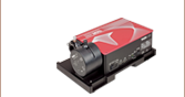
Flip up mounts are convenient for quick power measurments from a static location. The sensor can be placed in the path of the laser beam for the power measurment and flipped down during normal operation of the system.
FM90 Right Angle Flip-Mounts are shown to the right. Thorlabs also offers the TRB1 Articulating Post Mount. The lockable articulating mount offers almost unlimited positioning of the sensor head. The articulating mount is shown on an S13xC Slim Photodiode Sensor below.


The Standard Photodiode Sensors also feature SM1 threaded connections on the front face. The SM1 theading provides easy mounting to 1" lens tube systems and quick release mounts.
Shown to the right are the KB1P Quick-Release Post Mount and QRC1A Quick-Release 30 mm Cage Mount. Both mounts feature SM1 threaded connections to the sensor heads.
Note: Due to the thickness of the S12xC sensor, the QRC1A and CP44F (shown below) quick release mounts can only be fully removed from the cage system by backing them off an open end. The two mounts are easily removed from the cage system if only three cage mounts are used. See the picture on the right.
Thorlabs also offers the CP44F 30 mm Cage Plates with Quick-Release Mounts. These mounts feature magnetically coupled mounting for easy and repeatable mounting.
Note: Like the QRC1A, the CP44F can not be removed from a closed cage system.
Slim Photodiode Sensor Mounting Options

Thorlabs' Slim Photodiode Sensors are designed to fit into tight optic arrangements such as cages, lens tubs, and optic dense free space arrangements.
Shown to the right is a S130C Sensor inserted into a 30 mm cage system. The application shown highlights the ease for which the sensor can be inserted into the cage, and the minimal space needed to take a power measurment.
The Slim Photodiode Sensors may also be mounted on a TRB1 Articulating Mount. This mount allows repeatable insertion of the sensor into tight optic arrangements. After the measurement is made, the sensor may be rotated out of the beam path for normal operation.
Microscope Slide Photodiode Sensor Mounting Options

S170C Mounted on a Post
The S170C may be post mounted via the 8-32 (M4) tap in the side of the housing.

The S170C microscope slide power Sensor is designed so that it can be mounted directly in a microscope slide holder. The 76.0 mm x 25.2 x 5.0 mm sensor head has the same footprint as a standard microscope slide and is compatible with most standard upright and inverted microscopes. The photo to the right shows the power sensor flipped over so that the engraved back of the housing can be used for alignment.
This power sensor also has an 8-32 (M4) tap for post mounting. In the photo to the far right, an RA90 is used with two Ø1/2" posts to mount the sensor head in a horizontal orientation.
Integrating Sphere Photodiode Sensor Mounting Options

Thorlabs' Integrating Sphere Photodiode Sensor provides a low loss cavity for diverging, non-uniform, or off-axis beam measurements. These integrating spheres are ideal for all fiber based applications due to the beam divergence at the end of the fiber.
Shown to the right is an S140C Integrating Sphere with S120-FC Fiber Adapter. Also shown is an S140C with a S140-BFA Bare Fiber Adapter. The Bare Fiber adapter features a mounting clamp and light shield to decrease interference from ambient light.
Compact Fiber Photodiode Sensor Mounting Options

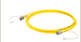
Thorlabs' Compact Fiber Photodiodes are the ideal choice for a portable, fiber coupled power meter. The S15xC sensors are compatible with a wide variety of fiber connections. PM20-xx adapters are available to couple FC, APC, SMA, ST, SC, and LC connectors with the sensors. Shown to the right is a S150C Sensor with FC and SMA connector adapters.
Shown to the far right is a PM100D console with S150C sensor connected to a FC connectorized optical fiber. This setup is ideal for portable in the lab and in the field use.
Pyroelectric Energy Sensor Mounting Options

Thorlabs' Pyroelectric Energy Sensors are ideal for measuring pulsed sources. These pyroelectric sensors provide direct energy readings for those sources. The sensors are designed to handle medium to high energy pulses from Excimer, YAG, and other high power lasers.
Mounting options include post (with insulating adapter) and cage configurations, shown to the right.
Compatible Power Meters
- PM100A Analog Power and Energy Meter Console
- PM100D Digital Power and Energy Meter Console
- PM101 Series Power Meter Interfaces with External Readout (Version 2.0 or Later)
- PM102 Series Power Meter Interfaces with External Readout (Version 2.1 or Later)
- PM100USB USB Interface Digital Power and Energy Meter
- PM400 Capacitive Touchscreen Power and Energy Meter Console
- PM160, PM160T, and PM160T-HP Wireless Handheld Power Meters with Bluetooth® Technology
- PM16 Series Compact USB Power Meters
The Optical Power Monitor software is not compatible with the PM320E Benchtop Power Meter.
Optical Power Monitor
The Optical Power Monitor GUI software features power measurement, readout from up to eight power meters, and remote wireless operation.
For details on specific software features, please see the user manual, which can be downloaded here.
Users interested in the legacy Power Meter Software can find it by visiting the software page here.
The PM101 Series Power Meters are only compatible with version 2.0 or later. The PM102 Series Power Meters are only compatible with version 2.1 or later.
Optical Power Monitor GUI Software for Touchscreen, Handheld, and USB-Interface Power Meters
Features
- Operate up to Eight Power Meters Simultaneously
- Record and Analyze Measurements in Real Time
- Intuitive Analog Display and Graphing Modes
- Configurable Long-Term Data Logging
- Also Supports Position Measurements with Thermal Position & Power Sensors
- Compatible with USB and Bluetooth® Connections
The Optical Power Monitor software GUI enables seamless control of up to eight power meters that are connected via USB, RS232, or Bluetooth® wireless technologya. The latest software, firmware, drivers, and utilities for these power meters can be downloaded here.
Multiple data measurement and analysis functions are integrated into the GUI package. The interface offers a user-friendly design with minimal use of color and low brightness that is ideal use in dark lab environments while wearing laser safety glasses. Measured data can be displayed in real time as a simulated analog needle, digital values, line graph, or bar graph. Continuously logged and short-term measurements can be recorded for data viewing and analysis at a later point. A built-in statistics mode analyzes measured data and continuously updates to reflect new measurements within the pre-determined measurement period. Beam position measurements are also supported when used with our thermal position & power sensors.
The Optical Power Monitor software package installs the GUI, which then can be used to control the touchscreen, handheld, or USB-interface power meters. Firmware updates for supported power meters are also available. Programming examples and drivers for interfacing with our power and energy meter consoles using LabVIEW, C/C++, Visual C#, and Python are installed with the software; refer to the manual for details.
Please note that the Optical Power Monitor Software uses different drivers than the Power Meter Utilities Software and Thorlabs recommends using the new driver TLPM.dll. For users who wish to use the legacy Power Meter Software or use custom software designed using the older PM100D.dll driver, a Power Meter Driver Switcher program is included for easy swapping of the installed driver between the two versions.
a. The PM160, PM160T, and PM160T-HP power meters are equipped with Bluetooth® connections.

Click to Enlarge
Power Measurement Mode: Set up and configure up to eight power meters.

Click to Enlarge
Power Tuning Mode: Simulated analog needle and digital measurement value provided. Delta Mode, enabled above, shows the fluctuation range during the measurement period.

Click to Enlarge
Power Statistics Mode: Calculate numerical statistics for a pre-determined measurement period. The panel displays the analyzed values in a bar graph and the results as numerical values.

Click to Enlarge
Position Tuning Mode: Tuning mode can be used with a thermal position & power sensor to aid in beam alignment.

Click to Enlarge
Position Statistics Mode: Statistics mode also provides aggregate information for thermal position & power sensors.

Click to Enlarge
Data Logging: Enable long-term measurement and simultaneous recording from up to eight power meters. Save data as .csv files for later processing while measurement results are displayed in a graph in real time.

Click to Enlarge
The PM160 wireless power meter, shown here with an iPad mini (not included), can be remotely operated using Apple mobile devices.
This tab outlines the full selection of Thorlabs' power and energy sensors. Refer to the lower right table for power meter console and interface compatibility information.
In addition to the power and energy sensors listed below, Thorlabs also offers all-in-one, wireless, handheld power meters and compact USB power meter interfaces that contain either a photodiode or a thermal sensor, as well as power meter bundles that include a console, sensor head, and post mounting accessories.
Thorlabs offers four types of sensors:
- Photodiode Sensors: These sensors are designed for power measurements of monochromatic or near-monochromatic sources, as they have a wavelength dependent responsivity. These sensors deliver a current that depends on the input optical power and the wavelength. The current is fed into a transimpedance amplifier, which outputs a voltage proportional to the input current.
- Thermal Sensors: Constructed from material with a relatively flat response function across a wide range of wavelengths, these thermopile sensors are suitable for power measurements of broadband sources such as LEDs and SLDs. Thermal sensors deliver a voltage proportional to the input optical power.
- Thermal Position & Power Sensors: These sensors incorporate four thermopiles arranged as quadrants of a square. By comparing the voltage output from each quadrant, the unit calculates the beam's position.
- Pyroelectric Energy Sensors: Our pyroelectric sensors produce an output voltage through the pyroelectric effect and are suitable for measuring pulsed sources, with a repetition rate limited by the time constant of the detector. These sensors will output a peak voltage proportional to the incident pulse energy.
| Console Compatibility | |||||||
|---|---|---|---|---|---|---|---|
| Console Item # | PM100A | PM100D | PM400 | PM320E | PM101 Series |
PM102 Series |
PM100USB |
| Photodiode Power |  |
|
|
|
|
- | |
| Thermal Power | |
|
|
|
|
|
|
| Thermal Position | - | - | |
- | - | |
- |
| Pyroelectric Energy | - | |
|
|
- | - | |
Power and Energy Sensor Selection Guide
There are two options for comparing the specifications of our Power and Energy Sensors. The expandable table below sorts our sensors by type (e.g., photodiode, thermal, or pyroelectric) and provides key specifications.
Alternatively, the selection guide graphic further below arranges our entire selection of photodiode and thermal power sensors by wavelength (left) or optical power range (right). Each box contains the item # and specified range of the sensor. These graphs allow for easy identification of the sensor heads available for a specific wavelength or power range.
| Photodiode Power Sensors |
|---|


| Thermal Power Sensors |
|---|


| Thermal Position & Power Sensors |
|---|


| Pyroelectric Energy Sensors |
|---|


Sensor Options
(Arranged by Wavelength Range)

Sensor Options
(Arranged by Power Range)


| Posted Comments: | |
MKiess
(posted 2020-12-14 06:34:06.0) Thank you for your feedback. Please check that you have the latest firmware installed on the PM100D. We have made a few changes regarding the SD card. You can find the firmware download at the link below:
https://www.thorlabs.de/software_pages/ViewSoftwarePage.cfm?Code=OPM user
(posted 2020-11-18 12:44:15.56) Is there a way to reset all settings/memory to the factory default? MKiess
(posted 2020-11-19 09:58:02.0) Thank you very much for your inquiry. Depending on the sensor used, the PM100D can be reset to the default settings for the respective sensors (thermopile, photodiodes, pyroelectric). This can be done under 'System Menu \ Measurement Settings' for the corresponding sensor. Alexander Kuznetsov
(posted 2020-06-30 10:25:33.08) I have a question about the drivers TLPM_32 and PM100D_32.
In our lab, we have a custom software to communicate with several PM100D remotely (e.g. the PM100D is connected to one PC and a user communicates with it from another PC). Such remote communication using PM100D_32.dll via NI-Visa Server works fine. However, devices configured to use the TLPM_32.dll driver are not "visible". Switching the driver to PM100D_32.dll solves it. However I would like to know, how would one achieve the remote communication with the device using TLPM_32.dll?
Thank you in advance. dpossin
(posted 2020-07-03 03:53:47.0) Dear Alexander,
Thank you for your feedback. We switched our software from the NI-VISA based driver PM100D.dll to the more robust driver architecture TLPM.dll. However if you need the old driver for your application we provide a tool called power meter driver switcher is installed together with the power meter software. Please find instructions how to change between the drivers in section 7 here: https://www.thorlabs.com/software/MUC/OPM/v2.2/TL_OPM_V2.2_web-secured.pdf. Also the commands are different compared to the old NI-VISA based driver. Instructions on programming the TLPM driver can be found here: C:\Program Files (x86)\IVI Foundation\VISA\WinNT\TLPM\Manual. I am reaching out to you in order to provide further support. BINBIN ZHAO
(posted 2020-05-04 01:29:02.887) Is there any example of MATLAB code used to control the PM100D and record the power automatically? MKiess
(posted 2020-05-05 10:38:32.0) This is an response from Michael of Thorlabs. Thank you very much for your inquiry. I have contacted you directly to provide further information. Yangyang Liu
(posted 2020-01-09 15:12:26.583) I am using PM100D. Recently, I want to update the firmware. And I connect the PM100D to computer by the monitor software. When I use the software to update the firmware there is always a warning that "user abort the download operation" but I do nothing. Hope for your answer. Thanks. Regards, Yangyang Liu. nreusch
(posted 2020-01-10 08:52:49.0) This is a response from Nicola at Thorlabs. Thank you for contacting us. Could you please check whether you enabled the firmware download mode on the PM100D console (System Menu -->
Console Settings -->
Firmware Upload -->
Enabled) before trying to install the new firmware with the DFU wizard? A local Tech Support representative will contact you for further troubleshooting. Junji Okamoto
(posted 2019-12-12 09:13:59.773) I would like to know about "analog output" of PM100D.
Q1, Is the output voltage from analog output "DC" voltage? (Is its wave shape flat?)
Q2, Is the output voltage basically go from 0V to +2.0V? (In a Manual, from -0.3V to +2.3V) wskopalik
(posted 2019-12-12 11:13:29.0) This is a response from Wolfgang at Thorlabs. Thank you for your inquiry!
The voltage signal at the analog output is the amplified photo-diode current or the amplified thermal or pyroelectric sensor voltage. So the voltage will change corresponding to the power of the incident light. If the incident light is CW, the signal will be a flat voltage signal. If the incident light is however modulated or pulsed, the signal will be modulated or pulsed as well.
The range of 0V to 2V is the range in which you will get reliable measurement results. If e.g. the amplifier or the sensor are saturated, it is however possible that you get voltages in the range of -0.3V up to +2.3V. So the devices attached to the analog output should be able to handle voltages in this range without any damage.
I will contact you directly to provide further assistance. A. Devine
(posted 2019-12-02 15:49:34.81) While polling a thermopile sensor over USB with the PM100D (using the LabVIEW drivers), occasionally NaN is returned instead of an actual power reading value. This seems to happen most frequently when readings are taken too close together. I have solved the problem by adding a 20 second delay between readings, but this seems too large. I do not experience the same behavior with the PM200 or newer power meters. I would appreciate any insight as to why the meter is returning NaN so that I can work on a more elegant solution.
Thanks,
AD MKiess
(posted 2019-12-05 09:32:58.0) This is an response from Michael of Thorlabs. Thank you very much for your inquiry. I have contacted you directly to discuss the specifications and measurement procedure of your light source, as well as the programming to find a solution together. Ian Roberts
(posted 2019-10-29 19:32:01.613) Using the SCPI commands in the manual I can communicate with the PM100D over USB to read the instantaneous power, which works well. However, I want to record data at a high rate (ideally every millisecond) which is too fast for serially polling the device using the MEAS power command.
As the device can make measurements very rapidly and store the data to a CSV file, is it possible to read this data / transfer the file (once measurement is finished) over USB using SCPI commands? Or some other way (e.g. mounting the storage as a device the computer can access?)
I appreciate Thorlabs offer a driver package / GUI but having to install separate software is highly unattractive (/ not even possible in some situations due to lack of admin rights). Thanks. MKiess
(posted 2019-10-31 08:55:39.0) This is a response from Michael at Thorlabs. Thank you very much for the inquiry. The limitation here is due to the data transfer rate of USB. However, you can use the analog output, which has a bandwidth of up to 100kHz. I contacted you directly to find a suitable solution for your application together. DAVID KINGHORN
(posted 2019-06-07 20:44:24.12) What is the part number for the AC Battery Charger for the PM100D Console? MKiess
(posted 2019-06-12 05:05:45.0) This is a response from Michael at Thorlabs. Thank you very much for the inquiry. The AC adapter for charging the system battery is not a standard Thorlabs product and therefore not available on our website. But of course it is possible to get a replacement from us. I will contact you directly to discuss further steps. Samuel Gyger
(posted 2019-05-31 05:55:41.643) We have the devices for a long time now and it seems the battery becomes bad (S/N P0000874) and (S/N PM001464)
Is it possible to exchange the battery by ourselves. Are you selling replacement batteries? Or should we buy one online?
Regards,
Samuel Gyger dpossin
(posted 2019-06-06 09:56:01.0) Thank you for your feedback. It is not intended to change the battery by our customers but we offer to change the battery inhouse as a service. I will reach out to you directly in order to discuss the details. Eneko Lopez
(posted 2019-03-21 07:29:41.42) we have a PM100D console with a S121C sensor. Is there anyway to acquire data with matlab software? It would be very helpful for us.
Thank you! swick
(posted 2019-03-29 04:40:11.0) This is a response from Sebastian at Thorlabs. Thank you for the inquiry. It is possible to remote control our power meter via Matlab. I contacted you directly to provide assistance. Cao Duc
(posted 2019-03-21 10:37:56.82) we recently received the PM100D console and a pyroelectric energy sensor ES120C with accessories. I tried to connect the sensor and the console by the insulator, post, and post holder but there was no signal at the display of the console, although it recognized the sensor, i turned trigger number down to 3%, then when i touched the console or the sensor it started having some noise, but the noise also stopped when i stopped touching. I tried again with my laser source, there was signal again. Can you give me some advice; or the specific connecting or setting guide of those devices will be very helpful with me. Thanks you! swick
(posted 2019-03-29 04:57:09.0) This is a response from Sebastian at Thorlabs. Thank you for the inquiry.
The function principle for these sensors is different compared to Thermopiles or Photodiodes. Pyroelectric sensors (ES-Series) do only generate a signal when an optical pulse is detected.
The pulse energy needs to be larger than the threshold which is defined via trigger level thus when setting trigger level to very low values you can observe noise. The measurement value will be updated with each incoming pulse and when no pulses appear the measurement display will be held on the last measured value.
I contacted you directly to provide further assistance. jagroopastro5
(posted 2019-01-05 22:00:31.453) sir,
recently i have purchased the PM100D with S130VC sensor module. i have measured the He Ne laser power with it and same time corresponding current in current mode. when i compare with the response curve of the sensor, it is showing high responsivity ( 0.4 approx against 0.36 specified value and it varying non linearly with power? why it is so?
sir, do a high frequency oscillator device placed near sensor hear will affect the measurement of device? wskopalik
(posted 2019-01-08 07:30:13.0) This is a response from Wolfgang at Thorlabs. Thank you very much for your feedback!
There are different possible reasons for this, e.g. the coupling of the laser in the sensor, incorrect settings on the power meter or also tolerances in the power of the laser itself.
I will contact you directly so we can look into the details and find an explanation for these results. krzysztof.anders
(posted 2018-12-14 21:06:32.34) After deleting all files and directories on SD card I'm unable to write statistics file - every time I get Error 0x000000BE "Invalid directory name". I was trying also to format SD card (FAT32) and putting there PM100LOG directory - still the same problem nreusch
(posted 2018-12-20 07:28:56.0) This is a response from Nicola at Thorlabs. Thank you very much for reporting this issue. I will contact you directly for troubleshooting. jlm
(posted 2018-10-01 14:17:08.03) Hey
I am trying to interface to your console PM100D with a c++ program written in QT.
In the document https://www.thorlabs.com/software/MUC/OPM/v1.1/TL_OPM_V1.1_web-secured.pdf you state that I should find a header file at;
“C:\Program Files (x86)\IVI Foundation\VISA\WinNT\include\TLPM.h”
Unfortunately I cannot locate such a file. I tried to repair the installation, but that did not mend the issue.
Can you help me? nreusch
(posted 2018-10-04 04:58:17.0) This is a response from Nicola at Thorlabs. Thank you for your inquiry. Yes, you are right the header file should be stored there. As this does not seem to be the case, I will send you the file via email. kay.schaarschmidt
(posted 2018-08-08 15:23:22.83) Hi,
we are trzing to use the Thorlabs software and labview to read out data from a PM100D. It worked for occasionally but suddenly an error kept occuring
Error -1073807345 occurred at PM100D Initialize.vi
Neither our self-made labview program, nor the Thorlabs software is currently working anymore.
Help appreciated. nreusch
(posted 2018-08-09 10:59:53.0) This is a response from Nicola at Thorlabs. Thank you for your inquiry! This seems to be a connection issue. I recommend to start troubleshooting this by using the Thorlabs software. Which version is installed on your PC? I will contact you directly to provide further assistance. user
(posted 2018-06-20 13:03:01.267) The cable on the wand is quite annoying. Will you ever offer a wireless sensor? YLohia
(posted 2018-06-20 04:26:31.0) We offer wireless sensors here: https://www.thorlabs.com/newgrouppage9.cfm?objectgroup_id=7233 hi243
(posted 2018-06-09 19:50:50.447) Hi,
I have the PL450B blue laser diode (450nm, 80mW) and I wish to measure the optical power coming out of this laser diode when it is pulsed at 30mW. The laser beam will be obstructed by a tuning fork element I am using, so the final optical power that I need to detect is around 1mW. My lab already has the PM100D console, so I just need help from you on deciding on a suitable power sensor/photo diode which can help me measure optical powers in the range 1mW-80mW (@450nm). Thanks mvonsivers
(posted 2018-06-13 09:03:15.0) This is a response from Moritz at Thorlabs. Thank you for your inquiry. The S121C would be suitable to measure powers of 500 nW - 500 mW in the wavelength range 400 - 1100 nm. Please note that for the measurement of pulsed sources special considerations have to be taken into account. I will contact you directly for further discussion. magnus.engholm
(posted 2018-03-26 09:49:29.23) Hi, We have the PM100D console and several photodiode and thermal sensors. Now, we are interested to measure the energy from a Xenon flash tube, hence a single pulse measurment. Can you please advice if/how this can be performed with the PM100D and what sensor neded? swick
(posted 2018-03-28 04:15:29.0) This is a response from Sebastian at Thorlabs. Thank you for the inquiry.
We recommend pyroelectric sensors for single pulse energy measurements. It depends on several optical parameters (pulse width, average power, beam diameter, repetition rate) if these sensors are suitable for your light source. I contacted you directly for assistance. pier29
(posted 2018-03-05 03:34:23.977) And I also want to know whether the device (S/N P0005229) is compatible with S120VC or not.
Spec. information says that "For the S120VC, these specifications are valid for devices with serial numbers 1203xxx or higher." wskopalik
(posted 2018-03-05 08:06:34.0) This is a response from Wolfgang at Thorlabs. Thank you very much for your inquiry!
Yes, the PM100D is compatible with the sensor S175C, S120VC and all other currently offered power meter sensors. The information you have found on the website for the S120VC is only concerning the specifications we give for this sensor, but not the compatibility. The specifications have changed a while ago, so for sensors with serial numbers lower than 1203xxx they are slightly different.
I will contact you directly to provide further assistance. pier29
(posted 2018-03-05 03:28:17.093) Hi, I already have PM100D (with S122C) and its serial number is P0005229. Is this device compatible with S175C?
Thank you. wskopalik
(posted 2018-03-06 09:17:38.0) This is a response from Wolfgang at Thorlabs. Thank you very much for your inquiry!
Yes, the PM100D is compatible with the sensor S175C and all other currently offered power meter sensors.
I will contact you directly to provide further assistance. louis_declerck
(posted 2017-12-08 19:13:13.053) Hi,
I am currently working with a spectrometer and the optical powermeter PM100A from thorlabs. My question to you guys is how the powermeter calculates the optical power from W into W/cm². Which area is chosen therefore? Another question is how the optical power is calculated itself. Is that done by a sort of integration over a range of wavelengths around the 'preferred wavelength' in the settings?
This is very important for me since the data from a spectroscope are not corresponding to data from the PM100A.
Sincerely yours,
Dr Louis Declerck swick
(posted 2017-12-18 03:41:00.0) This is a response from Sebastian at Thorlabs. Thank you for the inquiry.
PM100A can not display power densities so I think this is about PM100D. To display the power density in W/cm² in the right sub display it is necessary to enter the diameter of the incident beam or at an overfilled sensor the diameter of the sensor aperture. In the Meas Config menu the beam diameter can be set. I have contacted you directly for further assistance. lokirune
(posted 2017-11-08 00:29:25.34) Hi. I just lost power supply for PM100D. Where can I get them ? Thanks. mdiekmann
(posted 2017-11-10 06:23:27.0) This is a response from Meike at Thorlabs: Thank you for contacting us! We will get in touch with you directly to provide a quote for the power supply. aye.aung
(posted 2017-10-04 23:04:07.507) Dear Sir/Mdm,
We are using PM100D to measure optical power of LEDs. The wavelength of LED is 850 nm. The sensor that we used is S120C which can measure from 400nm-1100nm. We set 850 nm at PM100D and get measurement. We also tried to set various wavelengths (400, 500,.., 1000, 1100 nm and so on) and get measurements. It is observed that the peak power is occurred to be at 1100 nm and the power at 850nm is lower than most of the measurement powers at other wavelengths. Please kindly advise. Appreciate if you could contact us. Thanks. wskopalik
(posted 2017-10-05 04:54:48.0) This is a response from Wolfgang at Thorlabs. Thank you very much for your inquiry.
The wavelength you enter on the PM100D determines which responsivity is used to convert the current coming from the photodiode into a power values. This is necessary due to the spectral dependence of the responsivity of photodiodes. The sensor itself can however only measure the total power of a beam and cannot separate different wavelengths. This can lead to inaccuracies when you measure LEDs with a wide spectral distribution, because some parts of the spectrum may not be converted with the correct responsivity.
The difference in the results you see is basically the spectral dependence of the responsivity of the sensor. The responsivity is quite low around 400nm and 1100nm, in between it increases to a maximum at around 950nm - 1000nm. You should see the inverse of that in the power values when you change the wavelength which agrees with what you have seen.
I have contacted you directly to discuss all this in more detail. DingR.F.1987
(posted 2017-04-05 17:06:16.62) We would like to use S130vc & PM100D for measuring laser power. And we want to connect PM100D to NB via USB. Thus, what is the range of sampling rate will we obtain? Could we adjust it? Thank you. swick
(posted 2017-04-06 03:13:43.0) This is a response from Sebastian at Thorlabs. Thank you for the inquiry.
In Thorlabs Optical Power Meter Utility at "Log Config" you can adjust the Number of Samples, the Interval Time (min. 0.1s) and the Averaging. Via Labview the max. sampling rate would be 300Hz. abyangphilip
(posted 2017-03-02 20:40:14.097) I'm using your device PM100D. Just now the power meter can't read anything from the sensor and displayed Zero. It can read when I press the connector to the power meter with much strength. But it just can't read after I stop pressing the sensor connector. I try using other sensors and still the same. I'm wondering if the connecting part of the power meter has bad contact. Should I open the power meter and change a new connector? swick
(posted 2017-03-06 03:07:53.0) This is a response from Sebastian at Thorlabs. Thank you for the inquiry.
I have contacted you directly for assistance. ww40556
(posted 2016-12-19 22:02:45.42) I'm trying to connect PM100D by Visual C++, following by the Programming Reference, but I can't found the driver page. How could I connect PM100D by Visual C++. Thanks. wskopalik
(posted 2016-12-21 02:59:02.0) This is a response from Wolfgang at Thorlabs. Thank you very much for your inquiry. I am sorry for this issue and have contacted you directly to troubleshoot this in detail. user
(posted 2016-03-07 09:21:29.703) I'm using your device for the real time monitoring of few msec wide optical pulses, therefore I have the same problem as described in the previous message by gbeckford93.
By writing my own application which only requests the data, I have done precise timing tests on your device and found that it is possible to increase the number of samples per second by concatenating multiple "READ?" on the same SCPI command.
As example, by issuing the SCPI command "READ?;READ?;READ?;READ?;READ?" the instrument will respond with a string containing a list of 5 measurement that, if the averaging is set at 1 and auto range is disabled, are separated by 2.338 msec (2.369 msec with auto range enabled) instead of the 3 msec separation that would be obtained by retrieving the measurements by means of consecutive "READ?" in separate SCPI commands.
Unfortunately, the FIFO buffer dedicated to the device output is only 256 bytes and the buffer filling condition is not handled by the firmware so, if the SCPI responce string requires more than 256 bytes, all the exceeding chars will be lost.
Considering then that each measurement is transfered to PC using 15/16 ASCII chars (depending on sign), only up to 16 measurement can be requested on a single SCPI command without the risk of receiving an ASCII string truncated to 256 chars.
By retrieving then arrays of 16 measurements, rather than single values, my application is able to read from your device up to 416 samples per second that (a part a small gaps between the arrays) are equispaced by 2.338 msec
Considering that time requested for ADC conversion is only 0.333 msec, the remaining 2 msec are entirely spent by the device firmware to process the data and could certainly be significantly reduced if two additional SCPI Commands, rather standard in this kind of instruments, were implemented also in your device:
- "CONFigure:ARRay" and "READ:ARRay?"
to setup and retrieve an array of multiple
measurement in a single com shallwig
(posted 2016-03-09 05:34:09.0) This is a response from Stefan at Thorlabs. Thank you very much for your valuable feedback. We will review your ideas and check how we can improve the units here. As you left no contact data, please contact us at europe@thorlabs.com for further questions. gbeckford93
(posted 2016-01-27 14:31:47.583) Does the software currently available (For both single and multiple devices) allow readings of 1kHz? Even with the interval at 0 and the averaging at 1 the most I am able to get is around 300Hz.
If not then how can I increase the samples per second?
Thank you. shallwig
(posted 2016-01-28 06:39:37.0) This is a response from Stefan at Thorlabs. Thank you very much for your inquiry. The sampling speed of the currently available software is limited to around 300 Hz. This limitation has several reasons, mainly from the GUI which queries also the status of the device and sensor and saves the data into a file.This could be bypassed by writing a short own application which only requests the data. In the Software package also drivers for Labview, Visual Basic, C++ and C# are included.
You can download Power meter application notes for programming from the “Programming Reference” Tab http://www.thorlabs.com/software_pages/viewsoftwarepage.cfm?code=PM100x&viewtab=5
Another limitation for getting equidistant data will be the USB connection. Sampling at 1 kHz is possible by using the PM100Ds Analog output. The Bandwidth is DC-100 kHz dependent on the sensor.
I will contact you directly to check your application in more detail. chang.chen
(posted 2015-09-30 16:44:51.837) Hello,
I bought two these powermeters with silicon detectors. But one of the powermeter PM100D didn't work. It shows cannot detect the sensor. I have tested the sensor in the good powermeter, and the sensor works. Is there a way to fix the broken powermeter?
Thanks,
Dr. Chang Chen
imec, Belgium shallwig
(posted 2015-09-30 11:50:28.0) This is a response from Stefan at Thorlabs. Thank you very much for your inquiry. I am sorry for the problems you face with one of your power meters. I will contact you directly to troubleshoot this in detail. eh8423
(posted 2015-09-16 18:32:03.177) I am using the powermeter with some C code to measure the transmission through a device. Halfway through my measurement the powermeter stops working and gives the error that it cannot write to the serial port. Why is this? Am I sampling too fast? shallwig
(posted 2015-09-17 03:48:11.0) This is a response from Stefan at Thorlabs. Thank you very much for your inquiry. I am sorry for the problems you are facing with our device. We will contact you directly to troubleshoot this in detail. jeffb
(posted 2015-05-26 18:29:20.047) Are the S120VC and S120C detectors NIST traceable calibrated for irradiance? The detector aperture is specified as 9.5 mm but is the tolerance of the aperture negligible, calibrated for, or already accounted for in the specs?
thanks! shallwig
(posted 2015-05-27 06:48:28.0) This is a response from Stefan at Thorlabs. Thank you very much for your inquiry. All our detectors are only NIST traceable calibrated in terms of absolute power. The setup we use for calibrating our sensors can be found on our website in the power meter tutorial if you click on the “calibration” Tab: http://www.thorlabs.com/newgrouppage9.cfm?objectgroup_id=6188
We use a monochromator which has about 2mm beam diameter. Therefore the aperture dimensions and its tolerances are uncritical for the S120VC and S120C. Both have an input aperture of 9.5mm diameter.
First a reference scan is carried out and the reference current (IRef) vs. wavelength is recorded. This allows the calculation of the optical power at each wavelength step. The Reference photodiodes are recalibrated annually at PTB or NIST, which gives the traceability. After that we replace the reference by the diode under test (DuT) and repeat the wavelength scan. This time the current (IDuT) vs. wavelength gets recorded.
During any calibration scan, a monitor diode is used to observe power variations due to lamp aging. The ratio of the actual monitored value during calibration to that during the reference scan is used to correct the calibration scan. As soon as the deviation exceeds 1%, a repeated reference scan is carried out. The responsivity of the DuT is then calculated over the entire specified wavelength range of the DuT with a step size of 5 nm. These data sets (responsivity and wavelength) are saved to the sensor's memory, located in the DSUB connector. Additionally, the calibration data are printed out to the Certificate of Calibration and are saved to our server.
Irradiance you can also display with our power meter consoles by entering the beam diameter. But the given value is a calculation made from the measured optical power and the beams dimensions.
I will contact you directly to discuss your needs in more detail. lhkorea
(posted 2014-11-25 15:15:08.25) Hi. We have used a number of PM100Dand sensor head S155C and have some problems. These devices shows smaller power data than real value(measured by other sensor head). Furthermore, these shows radical power data change when 'Range' is changing to upper or lower range at 'Auto range on' state (for example, if power data is 44uW within ~45uW range, after then, the power data increases slightly over 45uW, the power data is just changed to around 130uW right after the measurement range is changed to ~450uW.) This problem applies to all PM100Ds and S155Cs we have. I think there is some problem about sensing calibration between pm100D and S155C(power measurement using a S146C sensor head has no problem now). At the first time when we used these devices, there was no problem like this. I don't know the reason of this problem exactly, but I guess this problem was caused since we used these devices by connecting to PC. Power measurement using PC software fixes the range option as 'Auto range', so we can't avoid this problem. Please reply asap. Thanks. shallwig
(posted 2014-11-25 03:57:58.0) This is a response from Stefan at Thorlabs. Thank you very much for your inquiry. I will contact you directly to troubleshoot this issue in detail. user
(posted 2014-02-28 08:14:35.767) This is a response from Juergen H. at Thorlabs. Thank you very much for your inquiry.
The analog output provides the amplified photodiode current or the amplified thermal or pyroelectric sensor voltage.
With thermal sensors the analog output shows the direct amplified and accelerated voltage response from the sensor. With pyroelectric sensors the signal from the analog output is the pulse response from the sensor prior to the peak detection circuit.
The signals from the analog outputs are not wavelength and zero corrected.
The analog output voltage is range dependent and can be calculated to:
U(out)[V] = 2V / full scale range value [V,A] x measurement value [V,A]
The analog output voltage can go from -0.3V to +2.3V. abul_ukproject
(posted 2014-02-27 17:15:14.057) Hi
we would like to know for the anaalog output of
0-2V, what does it correspond to in terms of power?
We are using an optical chopper and a lock-in amplifier hence the need has arisen for a dictionary to translate the voltage readings back into power. Please reply quickly so that we can proceed with our research.
Thanks from Singapore lee.cairns
(posted 2014-01-28 09:23:05.91) Hi, we have a number of these in various labs, and we frequently use these to log optical power over long periods of time. However, the units suffer from sporadic signal drop outs (over 7 drop outs in 48 hours!!) is there anything we can do to prevent this, or is this unit not designed to monitor power over long periods of time? tschalk
(posted 2014-01-28 10:35:46.0) This is a response from Thomas at Thorlabs. Thank you very much for your inquiry. I am sorry that you experience connection issues with our power meter. The device is designed to monitor power over long periods of time and 48 hours shouldn’t be an issue. Please check if you are using the latest firmware, Version 2.3.2, of ours. If this is not the case please perform an update, the latest firmware can be found here: http://www.thorlabs.de/software_pages/viewsoftwarepage.cfm?code=PM100x. For installation instructions please consult the users manual. I will also contact you directly in case that you experience any further difficulties. joe.zott
(posted 2013-12-30 15:34:25.703) I am a current PM100D customer. We own 3 devices currently and looking to purchase another. I am doing some testing now and seeing signal drop outs in the PC console that don't show up on the meter face and don't appear to be real. I am running newest firmware/software versions (2.3.2 etc.). Is there anyway to avoid this happening? jvigroux
(posted 2013-12-31 05:06:23.0) A response from Julien at Thorlabs: The discrepancy between what is shown on the computer and what is shown on the console is probably related to the fact that the refresh rate of the display is limited to 10Hz, while one can access much higher display rate on a computer. This however does not explain why there is the change in the first place. I will contact you directly to disucss the details of your set up and see what the origin of this problem could be. emeyersc
(posted 2013-12-17 14:57:47.157) We own a number of PM100D but seem to frequently lose the DC power supplies. Are you able to sell us those separately? tschalk
(posted 2013-12-18 05:28:32.0) This is a response from Thomas at Thorlabs. Thank you very much for your inquiry. We can provide the power supply separately. This is not a standard item, so you wont find it on the website. We will contact you directly with more detailed information. d.albach
(posted 2013-11-05 14:47:54.683) Dear Sir or Madam,
we lost our hard cases which are delivered together with the PM100D. Is there any chance to get the hard cases stand-alone?
Best Regards,
Daniel tschalk
(posted 2013-11-06 03:50:10.0) This is a response from Thomas at Thorlabs. Thank you very much for your inquiry. We can can provide the case separately. I will contact you directly with detailed information. snaghizadeh
(posted 2013-07-31 01:14:45.897) Dear Sir/Madam,
There is an example LabView VI on page 43 of operation manual(not quick reference) under section 6.3.2 Instrument Driver Example.
I could not find the related VI inside the USB stick that came with PM100D powermeter box.
Further, I do not understand what you exactly mean by "data carrier" in the manual, is it a folder name?
Finally, I was informed by a colleague that powermeter has an averaging circuitry inside it and we do not need to write any sub VI for it. That is sending command AVER is sufficient.
we have just powermeter sensors, does this mean that when we send the command AVER, the device automatically understands that "power" is going to be averaged?!
Thank you in advance for your time and help.
Regards,
SN jvigroux
(posted 2013-07-31 07:24:00.0) a response from Julien at Thorlabs: thank you for your inquiry! The Labview example should normally be included on the USB stick that is delivered together with the power meter. The file name is "PM100D Simple Example" which is in the folder Applications of the USB stick. I will contact you per email and send you the data. the data carrier means the USB stick. I am sorry if this point was not clear. Finally, concerning the averaging, you can indeed use the AVER command to modify the average count n_a so that the value returned is already the average of the last n_a measurement values. david.kortbawi
(posted 2013-07-24 17:36:02.92) I don't see calibration service the the PM100D (or sensors) listed in the catalog. Could you please provide pricing and turnaround time to calibrate a PM100D and S120C sensor. In case my e-mail does not come through, please send info to david.kortbawi@dkengineering.com
Thanks,
Dave tschalk
(posted 2013-07-25 06:02:00.0) This is a response from Thomas at Thorlabs. Thank you very much for your inquiry. The calibration service for our photodiode sensors can be found here: http://www.thorlabs.com/newgrouppage9.cfm?objectgroup_id=3328 at the bottom of the site. The services are called CAL1, CAL2, CAL-S130 and CAL-S132. For the S120C you would need the service CAL1. The calibration for the power meter console PM100D is included when you order a sensor calibration. I will contact you directly to provide more detailed information. paul.lauria
(posted 2013-07-19 13:00:07.21) We have a couple PM100D's with S120C, and I'm trying to use them for a time-study of laser power vs. time over about 10 minutes. But I am concerned about the laser warming the photodiode and thus influencing the measurement.
Do you have any suggestions--i.e. is there a temperature monitor on these photodiodes I could simultaneously monitor? Also, is there some plot of dark noise vs. temperature? jvigroux
(posted 2013-07-22 11:27:00.0) a response from Julien at Thorlabs: thank you for your feedback! the S120C only contain a resistive sensor to ensure that they are not overheating but cannot log the temperature directly. we offer a small USB temeprature logger (TSP01) that can be used in conjuncction with the power meter lines to log the temperature of the sensor over time. The requirement for such an external temperature logge rin this type of application is of course related to the incoming optical power. I will contact you directly to see which optin is the msot suited to your requirements. pt_tanyingjie
(posted 2013-06-19 04:37:51.34) I need to insert some labview source codes of PM100A/D into another measurement labview program. In the program, I need the power meter to set the wavelength of a monochromatic light, then measure the light intensity, meanwhile, save the wavelength value, light intensity into a file. Then, go to the next wavelength monochromatic light, then PM100 set this wavelength, measure the intensity,and so on.
The problem I encountered is, the labview source codes in the USB in the package(or from the Thorlabs webpage)cannot work. PM100 has no response to these labview source codes.(e.g. set wavelength). And many of them are bad subVIs.(e.g.PM100-PM200 Utility).
So could you help me with it?
Thank you very much again! tschalk
(posted 2013-06-20 09:22:00.0) This is a response from Thomas at Thorlabs. Thank you very much for your inquiry. The software which can be downloaded from our homepage (https://www.thorlabs.com/software_pages/ViewSoftwarePage.cfm?Code=PM100x) contains the sub VIs necessary to access all of the functions which you require for your software. The LabVIEW Library is located in the folder: C://Program Files/National Instruments/LabVIEW X(latest version on your pc)/instr.lib/PM100D. You can access the individual functions through the function panel of LabVIEW: Instrument I/O -> Instrument Drivers -> PM100D. Two important functions to get a response from the power meter are the PM100D Initialize.vi and the PM100D Close.vi. The device must be initialized before you can use the other functions to control the power meter. At the end of the program the device must be closed. If you don't use the initialization and closing there will be problems with getting any response from the device. I will contact you directly for more detailed information. user
(posted 2013-06-18 06:22:41.263) We have a PM100D and a S150C sensor. The sensor is specified to have a resolution of 10pW, yet the numeric view does not display any digits below 0.1nW. The statistics view and the PC utility have enough digits to display 10pW and below, so the information must be there. Is there any way to make the numeric view display more digits with the S150C? tschalk
(posted 2013-06-19 11:50:00.0) This is a response from Thomas at Thorlabs. The display of the PM100D has 4 digits which is unfortunately not configurable. The highest resolution is then 100pW. If you want to archive higher resolution you can use the statistics screen or a connection to the computer. When using the console remotely, you are able to achieve a resolution of 1pW. tttang
(posted 2013-03-13 09:32:44.11) We have a PM100D with firmware v1.1.0. It can not be updated to newest firmware. The firmware upload is enable. We can update the other PM100D with newer version(v2.xx) successfully. Would you be able to help us? Does it need other steps to do that? jvigroux
(posted 2013-04-02 11:52:00.0) a resposne from Julien at Thorlabs: Thank you for your feedback. This normally should not happen. I will contact you directly to help with the troubleshooting jacekgol
(posted 2013-02-28 08:24:21.04) A response from Julien at Thorlabs: thank you for your answer.
Can not I use the USB interface to the PC (~1kHz sample rate)? jvigroux
(posted 2013-03-04 08:41:00.0) A response from Julien at Thorlabs: you could use the USB logging software but please keep in mind that the sample rate is not fixed and will depend on your computer also. This means that you could possibly, based on your setup have a sample rate (when using the logging software) of a few 100Hz. This in turns means that you would have only a few point per laser cycle, which could potentially be a problem. jvigroux
(posted 2013-02-28 07:52:00.0) a response from Julien at Thorlabs: Thank you for your inquiry. The display of the PM100D has a refresh rate of 20Hz so that you will not be able to follow your 100Hz directly on the display. When setting the bandwidth to "high", you should however be able to see your signal both when using the logging program (~1kHz sample rate) or the analog output (100kHz bandwidth maximum). for modulation frequency at 1kHz, the only option is to use the analog output. jvigroux
(posted 2012-11-15 10:05:00.0) A response from Julien at Thorlabs: thank you for your inquiry. The S314C can withstand temperatures (constant operation) up to 85°. The lower limit of the temperature range is 0°. edulgergil
(posted 2012-11-15 14:42:02.08) Is there any operating temperature range for S314C thermal power head in order to get best efficiency? jvigroux
(posted 2012-06-20 08:14:00.0) A response from Julien at Thorlabs: Thank you for your feedback! The limitation of the data rate accessible through the software is to some extent limited by the software architecture. We are currently in the process of modifying the PM100 utility so as to allow the maximum possible sample rate (~1kS/s, hardware limited). We will release a beta version containing this feature at the beginning of the next week. sebastien.du.tremblay
(posted 2012-06-17 22:25:59.0) Hi,
We bought a PM100D with a S130C sensor last month. We are trying to quantify the power output (mW) of a blue DPSS laser sending 5 ms pulses using the PM100 utilities software. We are unable to achieve sufficient sampling rate with this software, even when setting averaging to minimum (i.e. 1) and interval between samples to zero. In that case, we obtain about 35 samples/sec (and a noisy signal). We would like to achieve a better sampling rate using this software (i.e. 3Ksamples/sec). Any suggestions ? Thanks ! tcohen
(posted 2012-05-25 09:47:00.0) Response from Tim at Thorlabs: Thank you for using our feedback tool! This happens if the console is in “Relative Measurement” operation mode. In this mode, the left and right sub-menus are fixed and used for “Ref” power and “P” current power, while the main display shows the difference with a + or – sign. If you push the delta “?” button to return to normal measurement mode, the sub menus will again be programmable. user
(posted 2012-05-24 18:26:27.0) I have two Thorlab meters, one of them I am able to set the right sub menu to µW/cm^2. The other Thorlabs meter does not allow me to do this through the menu commands. Have any of you encountered this before ? tcohen
(posted 2012-02-22 10:43:00.0) Response from Tim at Thorlabs to dayong-zhou: By clicking the "Software" tab on this webpage and clicking the link provided you can download the software that comes with the PM100D. When unzipped, look for the file named "Source Distribution" which will contain all of the .vi files. For convenience, the link is: http://www.thorlabs.com/software/MUC/PM100x/Software/Remote_Control_Application/PM100D-PM200_Utility_V4.0.zip dayong-zhou
(posted 2012-02-21 23:23:17.0) Just cannot find the LabVIEW examples mentioned in the Operation Manual for PM100D either in onlion Thorlabs softwares or in the attached SD stick. Could you email me these LabVIEW example programs?
Thank you,
D jvigroux
(posted 2011-12-27 09:23:00.0) A response form Julien at Thorlabs: Thank your for your feedback. This file is indeed missing from the example folder. I am sorry for the resulting inconvenience. We will add this file immediately. seberangjeli
(posted 2011-12-26 22:43:00.0) I bought PM100D recenty and now trying to use Labview program, but the main program ask for PM100D_Open.vi file which is not included with Thorlabs USB drive. Could you please send me the file? Thanks. Shahnan jjurado
(posted 2011-08-02 11:16:00.0) Response from Javier at Thorlabs to kging: Thank you very much for contacting us. The sampling rate of our PM100xxx power meters is 3000 samples/sec. This is the internal sampling rate of the console. Using the software, you can set up averaging, which is the number of measurements to be averaged, resulting in 1 measurement sample. You can also configure a number of samples to be taken and displayed, as well as an interval time between two averaging operations. kqing
(posted 2011-07-29 15:56:48.0) Whats the sampling rate?
Thanks. K lsy
(posted 2011-04-01 00:56:05.0) Suddenly, Our PM100D cant recognize S121C.
I think there is no problem with S121C,
cause our other device can identify the sensor.
PM100D indicates the sensor as "PD Adapter".
Whats the problem?
F.W version is V2.2
Plz help us.
Regards Sungyong lee jjurado
(posted 2011-02-09 17:48:00.0) Response from Javier at Thorlabs to ren_mengxin: Thank you very much for submitting your inquiry. All the C series sensors, including the S120VC, are compatible with the PM100D. ren_mengxin
(posted 2011-02-09 19:14:23.0) Is sensor S120VC compatible with console PM100D? We have gotten PM100D and want another sensor. tor
(posted 2010-11-15 08:57:40.0) A response to Vishal from Tor at Thorlabs: Thank you for your interest in our photodiode sensors. The measurement ranges, in watts, for our C-series photodiode sensors are shown below on this page. Please do not hesitate to contact me at techsupport@thorlabs.com if youd like some assistance selecting an appropriate sensor for your application. vishals
(posted 2010-11-15 02:23:20.0) Pls send photodiode measurement range in watt unit.
vishal sakarvadiya
vishals@sac.isro.gov.in Thorlabs
(posted 2010-08-18 09:04:39.0) Response from Javier at Thorlabs to Paulo Santos: Thank you very much for your feedback. The software drivers for the PM100 and PM100D power meters are not compatible. They were developed using different protocols, which makes control with a single program not possible. santos
(posted 2010-08-17 10:35:48.0) We have PM100 and PM100D power meters, which we would like to control with a single program. I would like to know if the drivers for the new model PM100D also work for the old model PM100.
Thanks in advance,
Paulo Santos Thorlabs
(posted 2010-07-15 11:48:29.0) Response from Javier at Thorlabs to last poster: thank you for your feedback. We are currently in the process of evaluating the power rating specifications for all our sensors. We will update all the values on the web shortly. user
(posted 2010-07-13 23:51:32.0) teh overview tab says "100 pW to 250 W" but the strongest sensor goes to 200W apalmentieri
(posted 2010-03-03 09:10:19.0) A response from Adam to Thorlabs to jpwilde: We have added this file to the software and emailed you a copy of the complete vi folder. This file is included in the folder that was sent out to you. jpwilde
(posted 2010-03-02 18:48:44.0) I recently purchased the PM100D (actually, the PM130D) and tried loading the LabView utility software application. I program in LabView and would like to use your source code. However, the main utility code (PM100D Utility.vi) is looking for a sub-VI that was not included with the source code.
Can you please send me: PM100D_Open.vi ?
Thanks,
Jeff Wilde
408-828-3296 apalmentieri
(posted 2010-01-29 11:20:56.0) A response from Adam at Thorlabs to ctrao2000: I will contact you directly to find the exact instruments that will suit your requirements. ctrao2000
(posted 2010-01-29 03:05:11.0) i needs some optical instruments for Ha noi university ò technology klee
(posted 2009-12-07 11:08:45.0) A response from Ken at Thorlabs to ag: With the PM100D, you can easily access the wavelength menu by pressing the wavelength key. The menu offers 8 individually configurable sensor independent wavelength settings.
To edit a wavelength keep the OK key pressed for 1 second. Set the desired wavelength with the arrow keys. ag
(posted 2009-12-04 11:07:37.0) One of the most annoying things about the old version was the huge number o key presses required to change the wavelength, does this do any better?
Nice to have a USB interface but it doesnt mention Mac or Linux... klee
(posted 2009-09-04 16:48:27.0) A response from Ken at Thorlabs to cye: You will be receiving a quote from our sales deparment shortly. cye
(posted 2009-09-04 15:27:43.0) Please send quotation for PM100D S121C
Thanks,
My information:
Chianping Ye, PhD
Division of Endocrinology
BIDMC & Harvard Medical School
330 Brookline Ave
E/CLS 7, 720
Boston, MA 02215
Telephone: 617-735-3353
Fax: 617-735-3323 jhartmann
(posted 2009-07-09 11:13:55.0) A response from Juergen at Thorlabs to charlesholbrow : There is no exposure time control for photo diode sensors like S120C - the photo diode delivers a current, proportional to optical power.
The required averaging is possible - see also manual, sction 4.2.6 "Statistics Display" charlesholbrow
(posted 2009-07-07 12:22:51.0) Is it possible to reduce the repetition rate of the meters reading? Is it possible to increase the exposure time of the connected photo diode?
I am using a S120C photo Diode sensor. Ideally, I would like to be able to press a button on the meter and display the average value recorded by the meter over the next second. klee
(posted 2009-06-26 17:42:13.0) A response from Ken at Thorlabs to ondine.suavet: You will need to use it with a sensor head that can measure 345nm, for example the S120VC or S130VC. Then you will need to make the wavelength correction for 345nm. For more details, please refer to the operating manual, which can be downloaded under the Documents and Drawings tab. ondine.suavet
(posted 2009-06-26 16:59:48.0) I would like to know if I can select the wavelength (340nm in my case)where the UV intensity is measured?
Thank you very much. Regards, Ondine Greg
(posted 2009-03-31 07:18:13.0) A response from Greg at Thorlabs to cslim: A member of our Technical Support group will send you the software ASAP. I apologize that we do not have this on our website already. We are working on adding it to the download section of our website (gray bar at top: Service -> Download). cslim
(posted 2009-03-29 01:16:56.0) We bought the thorlabs PM100D power meter but lost the CD. May I know where I can download the content in the CD?
Regards,
winston. Laurie
(posted 2009-03-06 16:23:31.0) Response from Laurie at Thorlabs to andyh: Thank you for your interest in our power and energy meters. Someone from our technical support staff will contact you shortly to offer a solution. andyh
(posted 2009-03-06 14:42:51.0) We just bought the old style meter (~2 months ago) along with a slim cell sensor and thermal sensor.
It appears now that we cannot get a second meter of the style that would fit our current sensor cells. Is that correct?
What would the cost be to change the connectors to the current style on our 2 sensor? We are interested in having two meter and sensors that are interchangeable. It looks like your product revisions have prevented us from achieving this.
What are our options? |
Thorlabs offers a wide selection of power and energy meter consoles and interfaces for operating our power and energy sensors. Key specifications of all of our power meter consoles and interfaces are presented below to help you decide which device is best for your application. We also offer self-contained wireless power meters and compact USB power meters.
When used with our C-series sensors, Thorlabs' power meter consoles and interfaces recognize the type of connected sensor and measure the current or voltage as appropriate. Our C-series sensors have responsivity calibration data stored in their connectors. The console will read out the responsivity value for the user-entered wavelength and calculate a power or energy reading.
- Photodiode sensors deliver a current that depends on the input optical power and the wavelength. The current is fed into a transimpedance amplifier, which outputs a voltage proportional to the input current. The photodiode's responsivity is wavelength dependent, so the correct wavelength must be entered into the console for an accurate power reading. The console reads out the responsivity for this wavelength from the connected sensor and calculates the optical power from the measured photocurrent.
- Thermal sensors deliver a voltage proportional to the input optical power. Based on the measured sensor output voltage and the sensor's responsivity, the console will calculate the incident optical power.
- Energy sensors are based on the pyroelectric effect. They deliver a voltage peak proportional to the pulse energy. If an energy sensor is recognized, the console will use a peak voltage detector and the pulse energy will be calculated from the sensor's responsivity.
The consoles and interfaces are also capable of providing a readout of the current or voltage delivered by the sensor. Select models also feature an analog output.
Consoles
| Item # | PM100A | PM100D | PM400 | PM320E |
|---|---|---|---|---|
| (Click Photo to Enlarge) |  |
 |
 |
 |
| Key Features | Analog Power Measurements | Digital Power and Energy Measurements | Digital Power and Energy Measurements, Touchscreen Control | Dual Channel |
| Compatible Sensors | Photodiode and Thermal Power | Photodiode and Thermal Power; Pyroelectric | ||
| Housing Dimensions (H x W x D) |
7.24" x 4.29" x 1.61" (184 mm x 109 mm x 41 mm) |
7.09" x 4.13" x 1.50" (180 mm x 105 mm x 38 mm) |
5.35" x 3.78" x 1.16" (136.0 mm x 96.0 mm x 29.5 mm) |
4.8" x 8.7" x 12.8" (122 mm x 220 mm x 325 mm) |
| Channels | 1 | 2 | ||
| External Temperature Sensor Input (Sensor not Included) | - | - | Instantaneous Readout and Record Temperature Over Time | - |
| External Humidity Sensor Input (Sensor not Included) | - | - | Instantaneous Readout and Record Humidity Over Time | - |
| GPIO Ports | - | 4, Programmable | - | |
| Source Spectral Correction | - | - | - | |
| Attenuation Correction | - | - | - | |
| External Trigger Input | - | - | - | |
| Display | ||||
| Type | Mechanical Needle and LCD Display with Digital Readout | 320 x 240 Pixel Backlit Graphical LCD Display | Protected Capacitive Touchscreen with Color Display | 240 x 128 Pixels Graphical LCD Display |
| Dimensions | Digital: 1.9" x 0.5" (48.2 mm x 13.2 mm) Analog: 3.54" x 1.65" (90.0 mm x 42.0 mm) |
3.17" x 2.36" (81.4 mm x 61.0 mm) |
3.7" x 2.1" (95 mm x 54 mm) |
3.7" x 2.4" (94.0 mm x 61.0 mm) |
| Refresh Rate | 20 Hz | 10 Hz (Numerical) 25 Hz (Analog Simulation) |
20 Hz | |
| Measurement Viewsa | ||||
| Numerical | ||||
| Mechanical Analog Needle | - | - | - | |
| Simulated Analog Needle | - | |||
| Bar Graph | - | |||
| Trend Graph | - | |||
| Histogram | - | - | ||
| Statistics | ||||
| Memory | ||||
| Type | - | SD Card | NAND Flash | - |
| Size | - | 2 GB | 4 GB | - |
| Power | ||||
| Battery | LiPo 3.7 V 1300 mAh | LiPo 3.7 V 2600 mAh | - | |
| External | 5 VDC via USB or Included AC Adapter | 5 VDC via USB | Selectable Line Voltage: 100 V, 115 V, 230 V (±10%) | |
Interfaces
| Item # | PM101 | PM102 | PM101A | PM102A | PM101R | PM101U | PM102U | PM100USB |
|---|---|---|---|---|---|---|---|---|
| (Click Photo to Enlarge) |  |
 |
 |
 |
 |
 |
 |
 |
| Key Features | USB, RS232, UART, and Analog Operation |
USB and Analog SMA Operation | USB and RS232 Operation | USB Operation | USB Operation | |||
| Compatible Sensors | PM101 Series: Photodiode and Thermal Power PM102 Series: Thermal Power and Thermal Position & Power |
Photodiode and Thermal Power; Pyroelectric |
||||||
| Housing Dimensions (H x W x D) |
3.80" x 2.25" x 1.00" (96.5 x 57.2 x 25.4 mm) |
3.94" x 2.25" x 1.00" (100.0 x 57.2 x 25.4 mm) |
3.78" x 2.25" x 1.00" (95.9 x 57.2 x 25.4 mm) |
3.68" x 2.25" x 1.00" (93.6 x 57.2 x 25.4 mm) |
3.67" x 2.38 " x 1.13" (93.1 x 60.4 x 28.7 mm) |
|||
| Channels | 1 | |||||||
| External Temperature Sensor Input (Sensor Not Included) |
NTC Thermistor | - | ||||||
| External Humidity Sensor Input (Sensor not Included) |
- | |||||||
| GPIO Ports | - | |||||||
| Source Spectral Correction | - | |||||||
| Attenuation Correction | - | |||||||
| External Trigger Input | - | |||||||
| Display | ||||||||
| Type | No Built-In Display; Controlled via GUI for PC | |||||||
| Refresh Rate | Up to 1000 Hza | Up to 300 Hza | ||||||
| Measurement Viewsb | ||||||||
| Numerical | Requires PCb | |||||||
| Mechanical Analog Needle | - | |||||||
| Simulated Analog Needle | Requires PCb | |||||||
| Bar Graph | Requires PCb | |||||||
| Trend Graph | Requires PCb | |||||||
| Histogram | Requires PCb | |||||||
| Statistics | Requires PCb | |||||||
| Memory | ||||||||
| Type | Internal Non-Volatile Memory for All Settings | - | ||||||
| Size | - | |||||||
| Power | ||||||||
| Battery | - | |||||||
| External | 5 VDC via USB or 5 to 36 VDC via DA-15 |
5 VDC via USB | ||||||

 Zoom
Zoom- Compact, Handheld, Power and Energy Meter Console
- Large 4" LCD Screen
- Long-Life Internal Li-Polymer Battery
- Pre-Installed 8 GB SD Memory Card for Data Storage
- Console is Calibrated and Includes Certificate of Calibration
Please note that sensors are not included with the PM100D console. For information about our compatible sensors, please see the sensor descriptions below. Thorlabs does offer a variety of Power Meter Kits with the PM100D Console bundled with several of our most popular sensors. Please visit our Power Meter Kits page for more details.
A recalibration service is available for the PM100D; contact Tech Support for details. Alternatively, if you have a corresponding sensor that needs recalibrating, you can include the PM100D with the sensor for recalibration at no additional cost. To order this service, scroll to the bottom of the page and select the appropriate Item # that corresponds to your sensor.

Click to Enlarge
S120C and CP44F Quick-Release Mount
- For General Purpose Optical Power Measurements
- Integrated Viewing Target for Easy Sensor Alignment
- Ø9.5 mm Sensor Aperture
- Sensor, Protective Cap, IR Target, and Thread Adapter Included
- Fiber Adapters Available Separately (See Table Below)
- See the Full Web Presentation for More Information
These Standard Photodiode Power Sensors are ideal for metering low power coherent and incoherent sources from the UV to the NIR. Each NIST-Traceable, calibrated sensor features an integrated viewing target for easy alignment, enhanced shielding against electromagnetic interference, an over-temperature-alert device, and a large Ø9.5 mm sensor aperture. The sensors are compatible with 30 mm cage systems, Ø1/2" posts, and SM1 (1.035"-40) lens tubes, and are ideal for free-space and fiber-coupled sources.
Thorlabs offers a recalibration service for these photodiode power sensors, which can be ordered below (see Item # CAL1 for Si sensors and Item # CAL2 for Ge sensors).
| Item #a | S120VC | S120C | S121C | S122C |
|---|---|---|---|---|
| Sensor Image (Click the Image to Enlarge) |
|
|
|
|
| Aperture Size | Ø9.5 mm | |||
| Wavelength Range | 200 - 1100 nm | 400 - 1100 nm | 400 - 1100 nm | 700 - 1800 nm |
| Power Range | 50 nW - 50 mW | 500 nW - 500 mW | 50 nW - 40 mW | |
| Detector Type | Si Photodiode (UV Extended) | Si Photodiode | Ge Photodiode | |
| Linearity | ±0.5% | |||
| Resolutionb | 1 nW | 10 nW | 2 nW | |
| Measurement Uncertaintyc | ±3% (440 - 980 nm) ±5% (280 - 439 nm) ±7% (200 - 279 nm, 981 - 1100 nm) |
±3% (440 - 980 nm) ±5% (400 - 439 nm) ±7% (981 - 1100 nm) |
±5% | |
| Responsivityd (Click for Plot) |  Raw Data |
 Raw Data |
 Raw Data |
 Raw Data |
| Coating/Diffuser | Reflective ND (OD1.5)e | Reflective ND (OD1)f | Reflective ND (OD2)g | Absorptive ND (Schott NG9) |
| Head Temperature Measurement | NTC Thermistor 4.7 kΩ | |||
| Housing Dimensions | Ø30.5 mm x 12.7 mm | |||
| Cable Length | 1.5 m | |||
| Post Mountinge,f,g | Universal 8-32 / M4 Tap, Post Not Included | |||
| Aperture Thread | External SM1 (1.035"-40) | |||
| Compatible Fiber Adapters | S120-FC, S120-APC, S120-SMA, S120-ST, S120-LC, and S120-SC (Not Included) | |||
| Compatible Consoles | PM400, PM100D, PM100A, and PM320E | |||
| Compatible Interfaces | PM101, PM101A, PM101R, PM101U, and PM100USB | |||
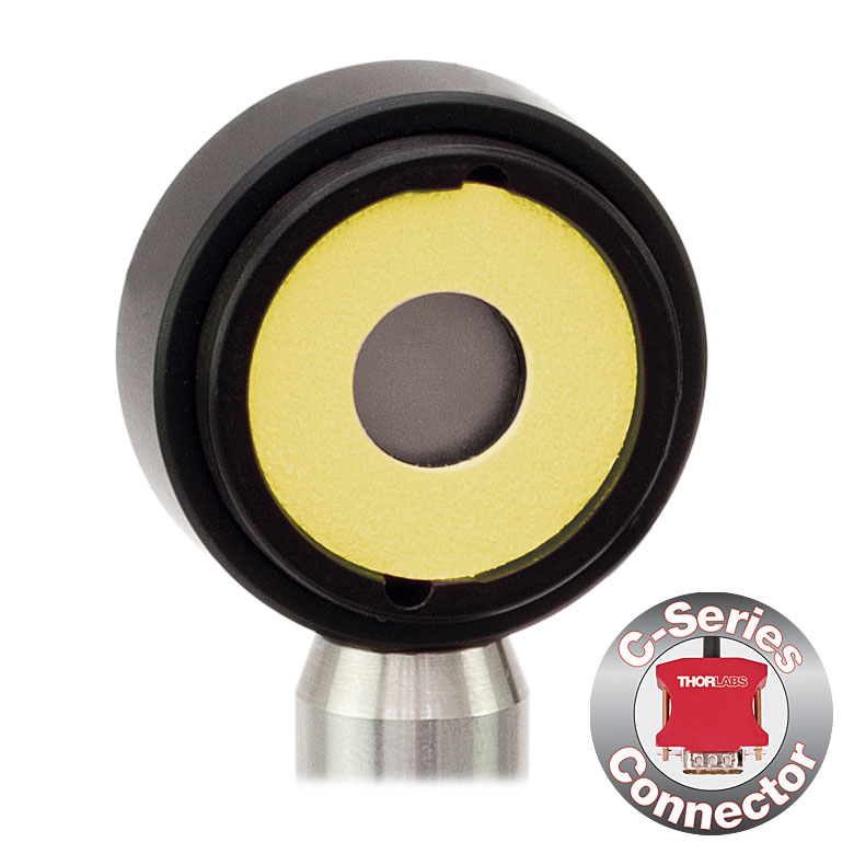
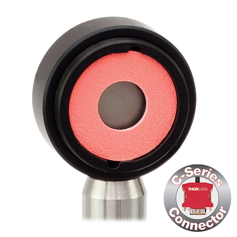

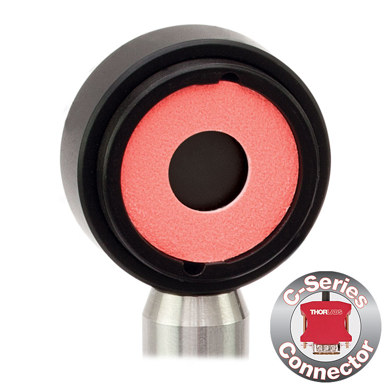


Click for Details S130C Photodiode Sensor Mounted in FiberBench System Using FBSM Mount
- For Optical Power Measurements in Confined Spaces
- Very Slim Design: 5 mm Thin on Sensor Side
- Ø9.5 mm Sensor Aperture
- Slideable ND Filter Automatically Changes Sensor Power Range
- Optional SM1A29 Adapter with VIS/IR Target and External SM1 Threading (More Details)
- Optional FBSM Mount with VIS/IR Target for FiberBench Systems (More Details)
- See the Full Web Presentation for More Information
These Slim Photodiode Power Sensors are designed to take optical source power measurements in locations where space and accessibility are at a premium. The 5 mm thin sensor end can fit between closely spaced optics, cage systems, and other arrangements where standard power meters may not fit. The NIST-Traceable, calibrated sensors also feature a large Ø9.5 mm sensor aperture and slideable neutral density filter for dual power ranges in one compact device.
A separately available SM1A29 adapter can be attached by 2 setscrews to any S130 series power sensor to mount fiber adapters, light shields, filters or any other SM1-threaded (1.035"-40) mechanics or optics. The FBSM Mount allows our S130 series power sensors to be mounted vertically into FiberBench systems for stable mounting with a minimal footprint.
Thorlabs offers a recalibration service for these photodiode power sensors, which can be ordered below (see Item # CAL-S130 for Si sensors and Item # CAL-S132 for Ge sensors).
| Item #a | S130VC | S130C | S132C | |
|---|---|---|---|---|
| Sensor Image (Click the Image to Enlarge) |
|
|
|
|
| Aperture Size | Ø9.5 mm | |||
| Wavelength Range | 200 - 1100 nm | 400 - 1100 nm | 700 - 1800 nmb | |
| Power Range (with Filter) |
500 pW - 0.5 mWc (Up to 50 mW)c |
500 pW - 5 mW (Up to 500 mW) |
5 nW - 5 mW (Up to 500 mW) |
|
| Detector Type | Si Photodiode (UV Extended) | Si Photodiode | Ge Photodiode | |
| Linearity | ±0.5% | |||
| Resolution | 100 pWd | 1 nWe | ||
| Measurement Uncertaintyf | ±3% (440 - 980 nm) ±5% (280 - 439 nm) ±7% (200 - 279 nm, 981 - 1100 nm) |
±3% (440 - 980 nm) ±5% (400 - 439 nm) ±7% (981 - 1100 nm) |
±5% | |
| Responsivityg (Click for Plot) | Raw Data |
Raw Data |
Raw Data |
|
| Coating/Diffuser | Reflective ND (OD1.5)c | Reflective ND (OD2)h | Absorptive ND (Schott NG9/KG3)b | |
| Housing Dimensions | 150 mm x 19 mm x 10 mm; 5 mm Thickness on Sensor Side | |||
| Cable Length | 1.5 m | |||
| Post Mounting | 8-32 and M4 Taps | |||
| Adapters (Not Included) | SM1A29: Add SM1 Thread and Viewing Target to Aperture Fiber Adapters Compatible with SM1A29 Adapter: S120-FC, S120-APC, S120-SMA, S120-ST, S120-LC, and S120-SC FBSM: Integrate Sensor into FiberBench Setups |
|||
| Compatible Consoles | PM400, PM100D, PM100USB, PM100A, and PM320E | |||
| Compatible Interfaces | PM101, PM101A, PM101R, PM101U, and PM100USB | |||
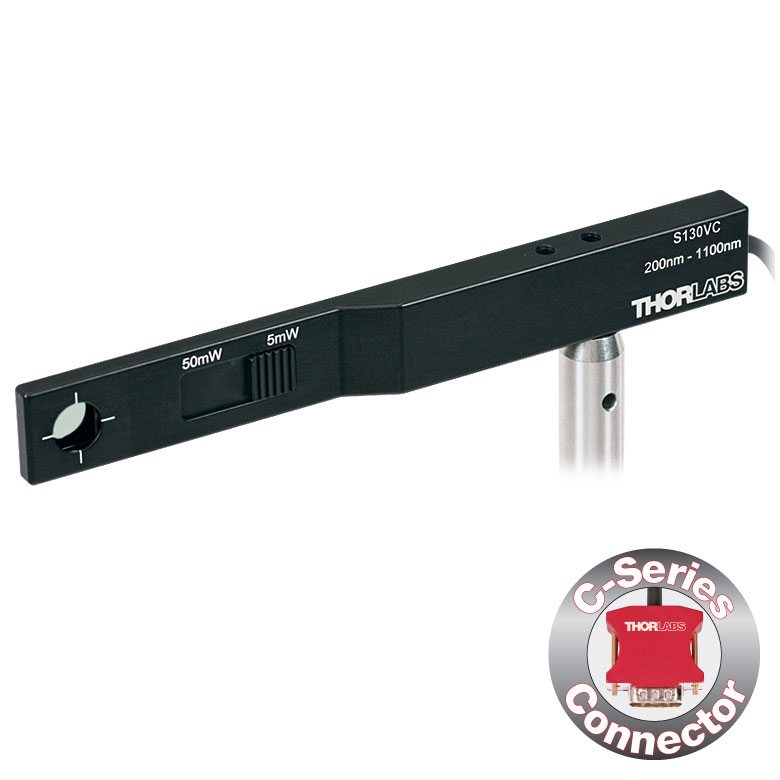
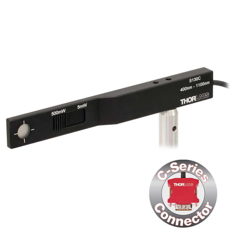
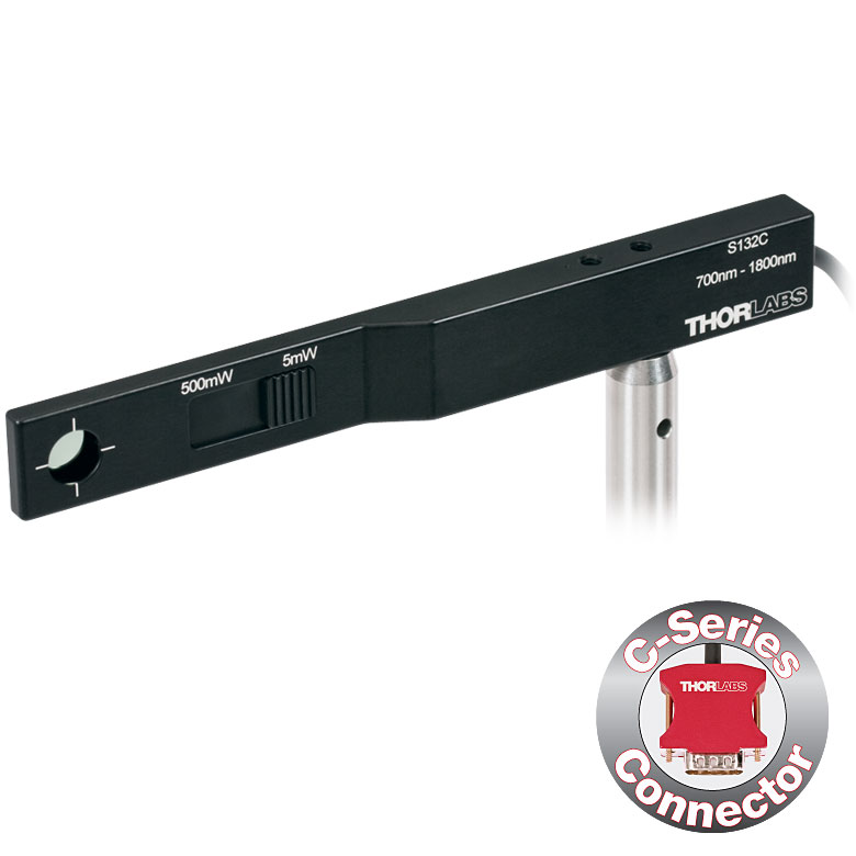
| Item #a | S170C |
|---|---|
| Sensor Image (Click Image to Enlarge) |
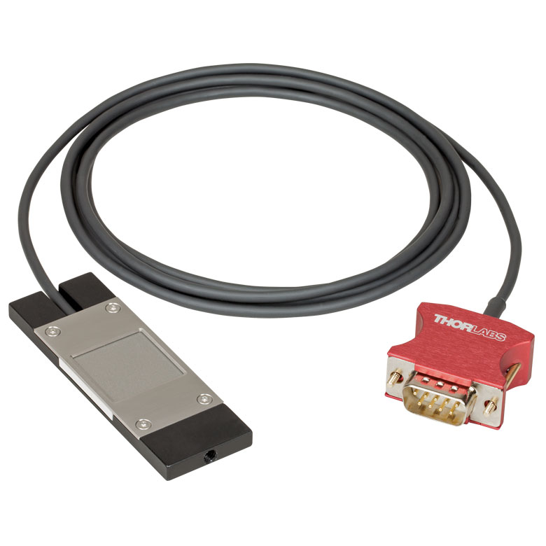 |
| Overall Dimensions | 76.0 mm x 25.2 mm x 5.0 mm (2.99" x 0.99" x 0.20") |
| Active Detector Area | 18 mm x 18 mm |
| Input Aperture | 20 mm x 20 mm |
| Wavelength Range | 350 - 1100 nm |
| Optical Power Working Range | 10 nW - 150 mW |
| Detector Type | Silicon Photodiode |
| Linearity | ±0.5% |
| Resolutionb | 1 nW |
| Calibration Uncertaintyc | ±3% (440 - 980 nm) ±5% (350 - 439 nm) ±7% (981 - 1100 nm) |
| Responsivityd (Click for Plot) | Raw Data |
| Neutral Density Filter | Reflective (OD 1.5) |
| Cable Length | 1.5 m |
| Post Mounting | Universal 8-32 / M4 Tap, Post Not Included |
| Compatible Consoles | PM400, PM100D, PM100A, and PM320E |
| Compatible Interfaces | PM101, PM101A, PM101R, PM101U, and PM100USB |
- Wavelength Range: 350 nm to 1100 nm
- Sensitive to Optical Powers from 10 nW to 150 mW
- Designed to Measure Optical Power at the Sample Plane of a Microscope
- Silicon Photodiode with Large 18 mm x 18 mm Active Area
- Sensor Housing Dimensions: 76.0 mm x 25.2 x 5.0 mm
- Index Matching Gel Utilized in Design to Prevent Internal Reflections
- Information Stored in Connector
- Sensor Data
- NIST- and PTB-Traceable Calibration Data
- Post Mountable via 8-32 (M4) Tap
The S170C Microscope Slide Power Sensor Head is a silicon photodiode sensor designed to measure the power at the sample in microscopy setups. The silicon photodiode can detect wavelengths between 350 nm and 1100 nm at optical powers between 10 nW and 150 mW. The sensor head's 76.0 mm x 25.2 mm footprint matches that of a standard microscope slide and is compatible with most standard upright and inverted microscopes.
The photodiode has an 18 mm x 18 mm active area and is contained in a sealed housing behind a neutral density (ND) filter with OD 1.5. A 20 mm x 20 mm indentation around the surface of the ND filter is sized to accept standard microscope cover slips. An immersion medium (water, glycerol, oil) may be placed in this well directly over the ND filter, or a cover slip may be inserted first to simplify clean up. The gap between the photodiode and the neutral density filter has been filled with an index matching gel in order to prevent internal reflections from causing significant measurement errors when using high NA objectives with oil or water.
The bottom of the sensor housing features a laser-engraved grid to aid in aligning and focusing the beam. In standard microscopes, this grid can be used for beam alignment before flipping the sensor head to face the objective for power measurements. In inverted microscopes, turn on the transmitted illuminator to align the grid on the detector housing with the beam, thereby centering the sensor in front of the objective. Alternatively, the diffusive surface of the ND filter can be used as a focusing plane.
Sensor specifications and the NIST- and PTB-traceable calibration data are stored in non-volatile memory in the sensor connector and can be read out by the latest generation of Thorlabs power meters. We recommend yearly recalibration to ensure accuracy and performance. Calibration may be ordered using the CAL1 recalibration service available below. Please contact technical support for more information.
Thorlabs also offers a Microscope Slide Sensor Head with a thermal sensor; for complete specifications, the full presentation can be found here.
| Item #a | S175C |
|---|---|
| Sensor Image (Click Image to Enlarge) |
 |
| Active Detector Area | 18 mm x 18 mm |
| Wavelength Range | 0.3 - 10.6 µm |
| Power Range | 100 µW - 2 W |
| Detector Type | Thermal Surface Absorber (Thermopile) |
| Linearity | ±0.5% |
| Resolutionb | 10 µW |
| Measurement Uncertaintyc | ±3% @ 1064 nm; ±5% @ 300 nm - 10.6 µm |
| Response Time | 3 s (<2 s from 0 to 90%) |
| Housing Dimensions | 76 mm x 25.2 mm x 4.8 mm (2.99" x 0.99" x 0.19") |
| Cable Length | 1.5 m |
| Housing Features | Integrated Glass Cover Engraved Laser Target on Back |
| Post Mounting | N/A |
| Cage Mounting | N/A |
| Aperture Thread | N/A |
| Compatible Consoles | PM400, PM100D, PM100A, and PM320E |
| Compatible Interfaces | PM101, PM101A, PM101R, PM101U, PM102, PM102A, PM102U, and PM100USB |

Click to Enlarge
Typical absorption curve for the S175C (glass and absorber). Note that this curve is representative, and the actual absorption across the spectrum will vary from unit to unit.

Click to Enlarge
The back of the S175C housing is engraved with the sensor specifications and a target for centering the beam on the sensor.
- Wavelength Range: 300 nm - 10.6 µm
- Sensitive to Optical Powers from 100 µW to 2 W
- Designed to Measure Optical Power in the Sample Plane of a Microscope
- Thermal Sensor with 18 mm x 18 mm Active Area
- 76.0 mm x 25.2 mm Footprint Matches Standard Microscope Slides
- Information Stored in Connector
- Sensor Data
- NIST- and PTB-Traceable Calibration Data
- See the Full Web Presentation for More Information
The S175C Microscope Slide Thermal Power Sensor Head is designed to measure the power at the sample in microscopy setups. The thermal sensor can detect wavelengths between 300 nm and 10.6 µm at optical powers between 100 µW and 2 W. The sensor head's 76.0 mm x 25.2 mm footprint matches that of a standard microscope slide and is compatible with most standard upright and inverted microscopes.
The thermal sensor has an 18 mm x 18 mm active area and is contained in a sealed housing behind a glass cover. An immersion medium (water, glycerol, oil) may be placed over the glass cover plate.
As seen in the image to the right, the bottom of the sensor housing features a laser-engraved target to aid in aligning and focusing the beam. In standard microscopes, the target can be used for beam alignment before flipping the sensor head to face the objective for power measurements. In inverted microscopes, turn on the trans-illumination lamp and align the target on the detector housing with the beam; this will center the sensor in front of the objective.
Sensor specifications and the NIST- and PTB-traceable calibration data are stored in non-volatile memory in the sensor connector and can be read out by the latest generation of Thorlabs power meters. We recommend yearly recalibration to ensure accuracy and performance. Calibration may be ordered using the CAL-S200 recalibration service available below. Please contact technical support for more information.
Thorlabs also offers a Microscope Slide Sensor Head with a photodiode sensor for low-power, high-resolution measurements; the full presentation may be found here.

Click to Enlarge
S142C and S140-BFA Bare Fiber Adapter (Sold Separately)

Click to Enlarge
S142C with the S120-FC Fiber Adapter (Included)
- For Measurements Independent of Beam Shape and Entrance Angle
- Integrating Sphere Design Acts as a Diffuser with Minimal Power Loss
- Ø5 mm, Ø7 mm, or Ø12 mm Input Aperture
- Removable S120-FC Fiber Adapter (FC/PC and FC/APC) Included
- Compatible Fiber Adapters for Terminated and Bare Fiber (See Table Below)
- See the Full Web Presentation for More Information
These Integrating Sphere Photodiode Power Sensors are the ideal choice for power measurements independent of beam uniformity, divergence angle, beam shape, or entrance angle, making them excellent for use with fiber sources and off-axis free space sources.
Our integrating spheres are designed for wavelength ranges from the visible through the NIR. Sensor heads for use between 350 and 2500 nm use a single Ø1" or Ø2" sphere made from Zenith® PTFE and feature a black housing to minimize reflected light around the entrance aperture. These sensors use either a silicon photodiode for detection in the 350 - 1100 nm range or an InGaAs photodiode for detection in the 800 - 1700 nm, 900 - 1650 nm, or 1200 - 2500 nm wavelength range.
The S180C integrating sphere for 2.9 - 5.5 µm uses two connected, gold-plated Ø20 mm spheres, with an entrance port in the first sphere and a port for the MCT (HgCdTe) detector located in the second sphere. Compared to single-sphere designs, the two-sphere configuration improves device sensitivity by minimizing the internal sphere surface area while still effectively shielding the detector from direct illumination. This design reduces the effect of input angle, divergence, and beam shape on the measurement result by effectively shielding the photodiode without the use of a baffle or other shielding mechanism.
The integrating spheres below feature large Ø5 mm, Ø7 mm, or Ø12 mm apertures, externally SM1-threaded (1.035"-40) front connections, enhanced shielding against electromagnetic interference, and an over-temperature alert sensor. Because of the large active detector areas of these sensors, the included S120-FC fiber adapter can be used with FC/PC- or FC/APC-terminated fiber. The externally SM1-threaded adapter can be removed using a size 1 screwdriver to place components closer to the window. NIST-traceable data is stored in the sensor connector.
Thorlabs offers a recalibration service for these photodiode power sensors, which can be ordered below. See Item # CAL1 for the S140C and S142C Si sensors; Item # CAL2 for the S144C, S145C, and S146C InGaAs sensors; and Item # CAL4 for the S148C InGaAs sensor or S180C MCT sensor.
| Item #a | S140C | S142C | S144C | S145C | S146C | S148C | S180C |
|---|---|---|---|---|---|---|---|
| Sensor Image (Click the Image to Enlarge) |
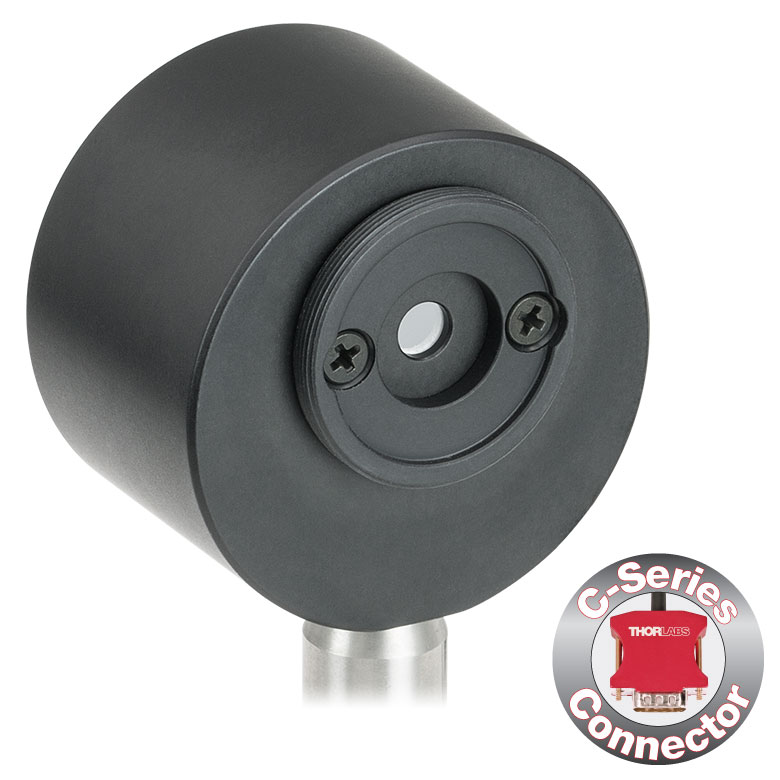 |
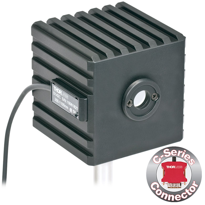 |
 |
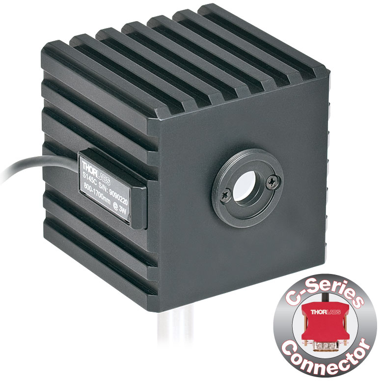 |
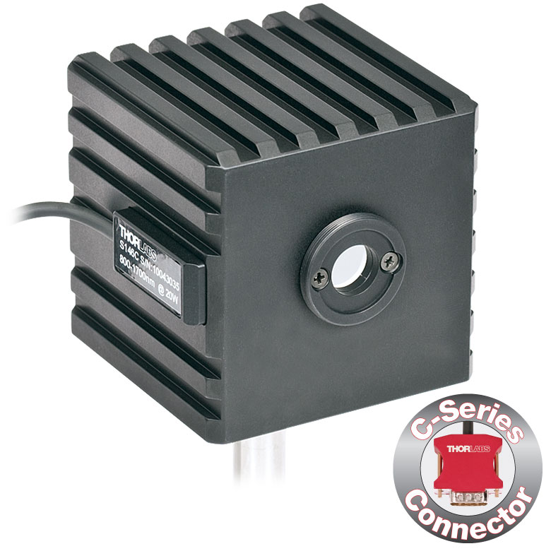 |
|
 |
| Aperture | Ø5 mm | Ø12 mm | Ø5 mm | Ø12 mm | Ø5 mm | Ø7 mm | |
| Wavelength Range | 350 - 1100 nm | 800 - 1700 nm | 900 - 1650 nm | 1200 - 2500 nm | 2.9 µm - 5.5 µm | ||
| Power Range | 1 µW - 500 mW | 1 µW - 5 W | 1 µW - 500 mW | 1 µW - 3 W | 10 µW - 20 W | 1 µW - 1 W | 1 µW - 3 W |
| Detector Type | Si Photodiode | InGaAs Photodiode | MCT (HgCdTe) Photodiode |
||||
| Linearity | ±0.5% | ||||||
| Resolutionb | 1 nW | 10 nW | 1 nW | 10 nW | |||
| Measurement Uncertaintyc |
±3% (440 - 980 nm) ±5% (350 - 439 nm) ±7% (981 - 1100 nm) |
±5% | |||||
| Responsivityd (Click for Plot) |
 Raw Data |
 Raw Data |
 Raw Data |
 Raw Data |
 Raw Data |
 Raw Data |
| Integrating Sphere Material (Size) |
Zenith® PTFE (Ø1") |
Zenith® PTFE (Ø2") |
Zenith® PTFE (Ø1") |
Zenith® PTFE (Ø2") |
Zenith® PTFE (Ø1") |
Gold Plating (Two Ø20 mm Spheres) |
|
| Head Temperature Measurement |
NTC Thermistor 4.7 kΩ | ||||||
| Housing Dimensions |
Ø45 mm x 30.5 mm | 70 mm x 74 mm x 70 mm | Ø45 mm x 30.5 mm | 70 mm x 74 mm x 70 mm | Ø45 mm x 30.5 mm | 59.0 mm x 50.0 mm x 28.5 mm |
|
| Cable Length | 1.5 m | ||||||
| Post Mounting | 8-32 and M4 Taps | ||||||
| Aperture Thread | Included Adapter with SM1 (1.035"-40) External Thread | ||||||
| Compatible Fiber Adapters |
S120-FC (Included) S120-APC, S120-SMA, S120-ST, S120-SC, S120-LC, and S140-BFA Bare Fiber Adapter (Not Included) |
||||||
| Compatible Consoles | PM400, PM100D, PM100A, and PM320E | ||||||
| Compatible Interfaces | PM101, PM101A, PM101R, PM101U, and PM100USB | ||||||

Click to Enlarge
PM100D with S150C Sensor and FC Cable
- For Fiber-Based Optical Power Measurements
- Compact Sensor Integrated into the Connector
- Integrated Design for use in the Field and Lab
- Includes PM20-FC Fiber Adapter
- S150C and S151C Sensors also Include PM20-SMA Adapters
- Compatible FC/APC, LC/PC, SC/PC, and ST Fiber Adapters Also Available (See Table Below)
- See the Full Web Presentation for More Information
The S15xC Compact Fiber Photodiode Power Sensor is designed to take power measurements from a wide variety of fiber coupled sources. The compact sensor, integrated into the power meter connector, features a unique integrated design housing the photodiode sensor, fiber coupling, and NIST-traceable data. Standard FC (and SMA - S150C and S151C) connectors are easily interchanged with a variety of standard fiber connectors.
Thorlabs offers a recalibration service for these photodiode power sensors, which can be ordered below (see Item # CAL1 for Si sensors and Item # CAL2 for InGaAs sensors).
| Item #a | S150C | S151C | S154C | S155C |
|---|---|---|---|---|
| Sensor Image (Click the Image to Enlarge) |
|
|
|
|
| Included Connectors | FCb & SMA | FCb | ||
| Wavelength Range | 350 - 1100 nm | 400 - 1100 nm | 800 - 1700 nm | |
| Power Range | 100 pW to 5 mW (-70 dBm to +7 dBm) |
1 nW to 20 mW (-60 dBm to +13 dBm) |
100 pW to 3 mW (-70 dBm to +5 dBm) |
1 nW to 20 mW (-60 dBm to +13 dBm) |
| Detector Type | Si Photodiode | InGaAs Photodiode | ||
| Linearity | ±0.5% | |||
| Resolutionc | 10 pW (-80 dBm) | 100 pW (-70 dBm) | 10 pW (-80 dBm) | 100 pW (-70 dBm) |
| Measurement Uncertaintyd | ±3% (440 - 980 nm) ±5% (350 - 439 nm) ±7% (981 - 1100 nm) |
±3% (440 - 980 nm) ±5% (400 - 439 nm) ±7% (981 - 1100 nm) |
±5% | |
| Responsivityf (Click for Details) |  Raw Data |
 Raw Data |
 Raw Data |
 Raw Data |
| Coating/Diffuser | N/A | Absorptive ND (Schott NG3) | N/A | |
| Head Temperature Measuremente | NTC Thermistor 3 kΩ | |||
| Aperture Thread | External SM05 (0.535"-40) | |||
| Fiber Adapters | Included: PM20-FC and PM20-SMA Optional: PM20-APC, PM20-LC, PM20-SC, and PM20-ST |
Included: PM20-FC Optional: PM20-APC, PM20-LC, PM20-SC, PM20-ST, and PM20-SMA |
||
| Compatible Consoles | PM400, PM100D, PM100A, and PM320E | |||
| Compatible Interfaces | PM101, PM101A, PM101R, PM101U, and PM100USB | |||

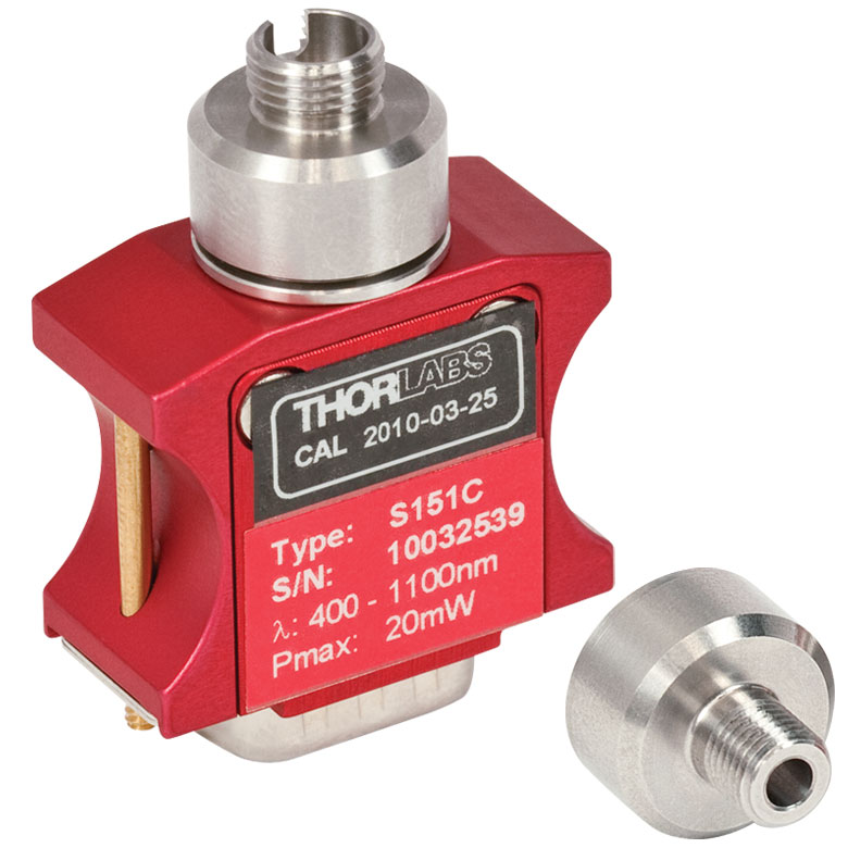
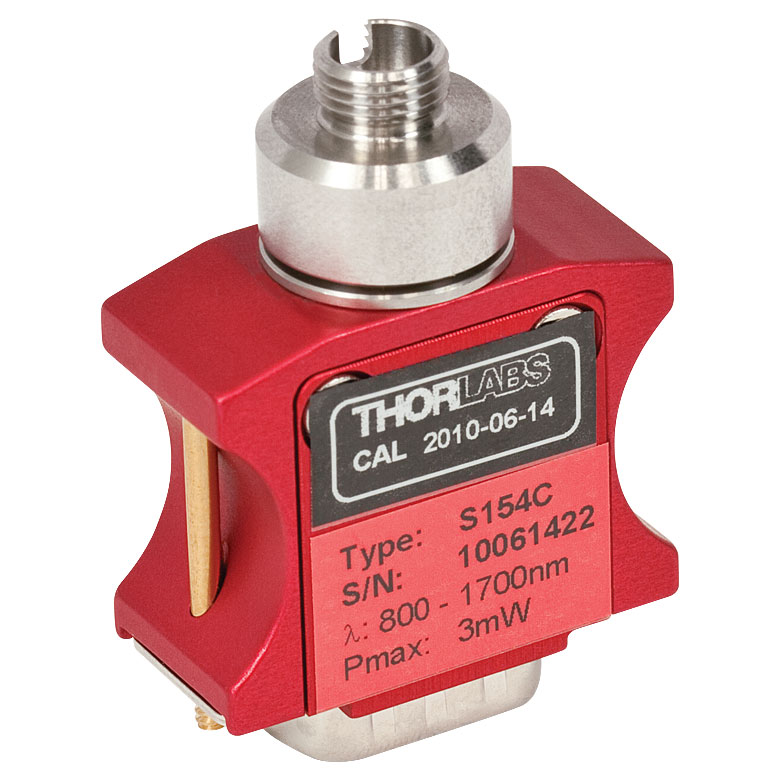

| Item #a | S401C | S405C |
|---|---|---|
| Sensor Image (Click the Image to Enlarge) |
 |
 |
| Wavelength Range | 190 nm - 20 µm | 190 nm - 20 µm |
| Optical Power Range | 10 µW - 1 W (3 Wb) | 100 µW - 5 W |
| Input Aperture Size | Ø10 mm | Ø10 mm |
| Active Detector Area |
10 mm x 10 mm | 10 mm x 10 mm |
| Max Optical Power Density | 500 W/cm² (Avg.) | 1.5 kW/cm² (Avg.) |
| Detector Type | Thermal Surface Absorber (Thermopile) with Background Compensation |
Thermal Surface Absorber (Thermopile) |
| Linearity | ±0.5% | ±0.5% |
| Resolutionc | 1 µW | 5 µW |
| Measurement Uncertaintyd | ±3% @ 1064 nm ±5% @ 190 nm - 10.6 µm |
±3% @ 1064 nm ±5% @ 250 nm - 17 µm |
| Response Timee | 1.1 s | 1.1 s |
| Cooling | Convection (Passive) | |
| Housing Dimensions (Without Adapter) |
(1.30" x 1.69" x 0.59") |
40.6 mm x 40.6 mm x 16.0 mm (1.60" x 1.60" x 0.63") |
| Temperature Sensor (In Sensor Head) |
NTC Thermistor | NTC Thermistor |
| Cable Length | 1.5 m | |
| Post Mounting | Universal 8-32 / M4 Taps (Post Not Included) |
Universal 8-32 / M4 Taps (Post Not Included) |
| 30 mm Cage Mounting | - | Two 4-40 Tapped Holes & Two Ø6 mm Through Holes |
| Aperture Threads | - | Internal SM05 |
| Accessories | Externally SM1-Threaded Adapter Light Shield with Internal SM05 Threading |
Externally SM1-Threaded Adapter |
| Compatible Consoles | PM400, PM100D, PM100A, and PM320E | |
| Compatible Interfaces | PM101, PM101A, PM101R, PM101U, PM102, PM102A, PM102U and PM100USB | |
- High Resolution of 1 μW or 5 μW
- S401C and S405C Have Thermistors Used to Monitor Temperature of Sensor Head
- S401C: Background Compensation for Low-Drift Measurements
- S405C: Accommodates Average Optical Power Densities up to 1.5 kW/cm²
- See the Full Web Presentation for More Information

Click to Enlarge
S401C Thermal Sensor with Included Light Shield
Thorlabs offers two broadband thermal power sensors designed to measure low optical power sources with high resolution. Each thermal sensor's broadband coating has a flat spectral response over a wide wavelength range, as shown in the plot below.
An aperture size of Ø10 mm allows for easy alignment and measurement of large-spot-size laser sources. For easy integration with Thorlabs' lens tube systems and SM1-threaded (1.035"-40) fiber adapters, each sensor has either external SM1 threading or includes an externally SM1-threaded adapter.
The S401C uses active thermal background compensation to provide low-drift power measurements. This is implemented through the use of two similar sensor circuits. One sensor circuit is the type all thermal power sensors share: it measures heat flow from light absorber to heat sink. The other sensor circuit monitors the ambient temperature. It is located within the housing and measures heat flow from heat sink towards the absorber. The measurements of the two sensor circuits are subtracted, which minimizes the effect of thermal drift on the laser power measurement. (For information about how the external thermal disturbances can affect thermal power sensor readings, see the Operation tab.) The broadband coating used on this thermal sensor offers high absorption at wavelengths between 0.19 and 20 µm (shown in the graph), which makes the sensor ideal for use with aligning and measuring Mid-IR Quantum Cascade Lasers (QCLs). The included, internally SM05-threaded (0.535"-40) light shield is shown in the photo to the right.
The S405C has internal SM05 (0.535"-40) threading that is directly compatible with SM05 lens tubes, and it can also connect directly to Thorlabs' 30 mm Cage Systems.
Thorlabs offers a recalibration service for these sensors, which can be ordered below (see Item # CAL-S200).

Click to Enlarge
The S405 shares the same absorption curve with the S415C, S425C, and S245C-L. (All are sold below.)
| Item #a | S415C | S425C |
|---|---|---|
| Sensor Image (Click Image to Enlarge) |
 |
 |
| Wavelength Range | 190 nm - 20 µm | 190 nm - 20 µm |
| Optical Power Range | 2 mW - 10 W (20 Wb) | 2 mW - 10 W (20 Wb) |
| Input Aperture Size | Ø15 mm | Ø25.4 mm |
| Active Detector Area |
Ø15 mm | Ø27 mm |
| Max Optical Power Density |
1.5 kW/cm² (Avg.) | 1.5 kW/cm² (Avg.) |
| Detector Type | Thermal Surface Absorber (Thermopile) | |
| Linearity | ±0.5% | ±0.5% |
| Resolutionc | 100 µW | 100 µW |
| Measurement Uncertaintyd |
±3% @ 1064 nm ±5% @ 250 nm - 17 µm |
±3% @ 1064 nm ±5% @ 250 nm - 17 µm |
| Response Timee | 0.6 s | 0.6 s |
| Cooling | Convection (Passive) | |
| Housing Dimensions (Without Adapter) |
(2.00" x 2.00" x 1.38") |
(2.00" x 2.00" x 1.38") |
| Temperature Sensor (In Sensor Head) |
NTC Thermistor | |
| Cable Length | 1.5 m | |
| Post Mounting | Universal 8-32 / M4 Taps (Post Not Included) |
Universal 8-32 / M4 Taps (Post Not Included) |
| 30 mm Cage Mounting | - | - |
| Aperture Threads | Internal SM1 | Internal SM1 |
| Removable Heatsink | Yes | Yes |
| Accessories | Externally SM1-Threaded Adapter | Externally SM1-Threaded Adapter |
| Compatible Consoles | PM400, PM100D, PM100A, and PM320E | |
| Compatible Interfaces | PM101, PM101A, PM101R, PM101U, PM102, PM102A, PM102U and PM100USB | |
- 100 µW Optical Power Resolution
- Thermistors Used to Monitor Temperature of Sensor Head
- Removable Heat Sinks Included
- See the Full Web Presentation for More Information
These thermal power sensors are designed for general broadband power measurements of low and medium power light sources. All include an externally SM1-threaded (1.035"-40) adapter, with threading concentric with the input aperture. The adapters are useful for mounting Ø1" Lens Tubes and Fiber Adapters (available below). The apertures of the S415C and S425C have internal SM1 threading.
These sensors operate with fast (<0.6 s) natural response times, and their removable heat sinks provide a high degree of flexibility to those interested in integrating them into custom setups or replacing the included heat sink with one that is water or fan cooled. If replacing the heat sink, please note that the replacement must provide heat dissipation adequate for the application.
Thorlabs offers a recalibration service for these sensors, which can be ordered below (see Item # CAL-S200).

Click to Enlarge
The absorption curves of each of the thermal power sensors designed for use with low and medium power optical sources.

Click to Enlarge
The absorption curves of each of the thermal power sensors designed for use with low and medium power optical sources.
- Thermistors Used to Monitor Temperature of Sensor Head
- S322C Has 4-40 Taps for Use with Our 30 mm Cage Systems
- S350C Has Ø40 mm Aperture Well Suited to Excimer and Other Lasers with Large Spot Sizes
- S425C-L Features Removable Heat Sink
- S322C is Fan Cooled with an Optical Power Range up to 200 W
- See the Full Web Presentation for More Information
These thermal power sensors are designed for general broadband power measurements of low and medium power light sources. With the exception of the S350C, all include an adapter with external SM1 (1.035"-40) threading concentric with the input aperture. This allows the sensors to be integrated into existing Ø1" lens tube systems in addition to being compatible with fiber adapters (available below). The aperture of the S425C-L has internal SM1 threading.
The S425C-L operates with a fast (<0.6 s) natural response time and has a removable heat sink, which provides a high degree of flexibility to those interested in integrating them into custom setups or replacing the included heat sink with one that is water or fan cooled. If replacing the heat sink, please note that the replacement must provide heat dissipation adequate for the application.
Thorlabs offers a recalibration service for these sensors, which can be ordered below (see Item # CAL-S200).
| Item #a | S350C | S425C-L | S322C |
|---|---|---|---|
| Sensor Image (Click Image to Enlarge) |
 |
 |
 |
| Wavelength Range | 190 nm- 1.1 µm, 10.6 µm | 190 nm - 20 µm | 250 nm - 11 µm |
| Optical Power Range | 10 mW - 40 W (60 Wb) | 2 mW - 50 W (75 Wb) | 100 mW - 200 W (250 Wb) |
| Input Aperture Size | Ø40 mm | Ø25.4 mm | Ø25 mm |
| Active Detector Area |
Ø40 mm | Ø27 mm | Ø25 mm |
| Max Optical Power Density | 2 kW/cm² (Avg.) | 1.5 kW/cm² (Avg.) | 4 kW/cm² (Avg., CO2) |
| Detector Type | Thermal Surface Absorber (Thermopile) | ||
| Linearity | ±1% | ±0.5% | ±1% |
| Resolutionc | 1 mW | 100 µW | 5 mW |
| Measurement Uncertaintyd | ±3% @ 351 nm ±5% @ 190 nm - 1100 nm |
±3% @ 1064 nm ±5% @ 250 nm - 17 µm |
±3% @ 1064 nm ±5% @ 266 nm - 1064 nm |
| Response Timee | 9 s (1 s from 0 to 90%) |
0.6 s | 5 s (1 s from 0 to 90%) |
| Cooling | Convection (Passive) | Forced Air with Fanf | |
| Housing Dimensions (Without Adapter, if Applicable) |
100 mm x 100 mm x 54.2 mm (3.94" x 3.94" x 2.13") |
100.0 mm x 100.0 mm x 58.0 mm (3.94" x 3.94" x 2.28") |
100 mm x 100 mm x 86.7 mm (3.94" x 3.94" x 3.41") |
| Temperature Sensor (In Sensor Head) |
NTC Thermistor | ||
| Cable Length | 1.5 m | ||
| Post Mounting | M6 Threaded Taps, Includes Ø1/2" Post, 75 mm Long |
Universal 8-32 / M4 Taps (Post Not Included) |
M6 Threaded Taps, Includes Ø1/2" Post, 75 mm Long |
| 30 mm Cage Mounting | - | - | Four 4-40 Tapped Holes |
| Aperture Threads | - | Internal SM1 | - |
| Removable Heatsink | - | Yes | - |
| Accessories | - | Externally SM1-Threaded Adapter | Externally SM1-Threaded Adapter |
| Compatible Consoles | PM400, PM100D, PM100A, and PM320E | ||
| Compatible Interfaces | PM101, PM101A, PM101R, PM101U, PM102, PM102A, PM102U and PM100USB | ||
| Item #a | S370C | S470C |
|---|---|---|
| Sensor Image (Click the Image to Enlarge) |
 |
 |
| Wavelength Range | 400 nm - 5.2 µm | 250 nm - 10.6 µm |
| Optical Power Range | 10 mW - 10 W (15 Wb) | 100 µW - 5 W (Pulsed and CW) |
| Input Aperture Size | Ø25 mm | Ø15 mm |
| Active Detector Area |
Ø25 mm | Ø16 mm |
| Max Optical Power Density | 35 W/cm² (Avg.); 100 GW/cm² (Peak) | |
| Detector Type | Thermal Volume Absorber (Thermopile) | |
| Linearity | ±1% | ±0.5% |
| Resolutionc | 250 µW | 10 µW |
| Measurement Uncertaintyd | ±3% @ 1064 nm ±5% @ 400 nm - 1064 nm |
±3% @ 1064 nm ±5% @ 250 nm - 10.6 µm |
| Response Timee | 45 s (3 s from 0 to 90%) |
6.5 s (<2 s from 0 to 90%) |
| Cooling | Convection (Passive) | |
| Housing Dimensions (Without Adapter, if Applicable) |
(2.95" x 2.95" x 2.02") |
(1.77" x 1.77" x 0.71") |
| Temperature Sensor (In Sensor Head) |
N/A | N/A |
| Cable Length | 1.5 m | |
| Post Mounting | M6 Threaded Taps, Includes Ø1/2" Post, 75 mm Long |
Universal 8-32 / M4 Tap (Post Not Included) |
| 30 mm Cage Mounting | Four 4-40 Tapped Holes | - |
| Aperture Threads | - | External SM1 |
| Accessories | - | |
| Compatible Consoles | PM400, PM100D, PM100A, and PM320E | |
| Compatible Interfaces | PM101, PM101A, PM101R, PM101U, PM102, PM102A, PM102U and PM100USB | |
- Designed for Optical Power Measurements of Nd:YAG Lasers
- Ideal for Applications with High Peak Pulse Powers
- S370C: Ø25 mm Aperture for Large-Spot-Size Beams
- S470C: High-Sensitivity for High-Peak-Power Pulses with Low Average Power
- See the Full Web Presentation for More Information
The S370C and S470C Thermal Sensors are designed to measure short and highly energetic laser pulses. All of these units are post-mountable for free-space applications and feature NIST-traceable data stored in the sensor connector.
These thermal power sensors are unique in that they have thermal volume absorbers, where our other thermal power sensors have thermal surface absorbers. The volume absorber consists of a Schott glass filter. Incident pulses are absorbed and the heat is distributed throughout the volume. In this way, pulses that would have damaged the absorption coating of a thermal surface absorber are safely measured by these thermal volume absorbers.
The S370C features a large Ø25 mm aperture ideal for large-spot-size beams, and it is compatible with average powers from 10 mW to 10 W (CW).
In comparison, the S470C is faster, as the glass absorber volume is reduced and other design parameters have been optimized for speed. This results in a different optical power range, with the ability to measure powers down to 100 µW. The Ø15 mm aperture is of the S470C is smaller, and it has a lower max average power of 5 W. Its 10 µW resolution is better than the 250 µW resolution of the S370C.
Thorlabs offers a recalibration service for these sensors, which can be ordered below (see Item # CAL-S200).

Click to Enlarge
This absorption curve is shown over a broader wavelength range than the sensors' operating ranges. See the table for the operating wavelength range of each sensor.

Click to Enlarge
ES220C Sensor Mounted in a 30 mm Cage System
- For General Purpose and High Energy Optical Pulse Measurements
- Black Broadband Coating with Flat Response Over a Wide Wavelength Range
- Ceramic Coating with High Damage Thresholds for High-Energy-Density Lasers
- Sensor Areas from Ø11 mm to Ø45 mm
- BNC Connector for Oscilloscope Use
- C-Series Connector Adapter for Use with Compatible Thorlabs Consoles and Interfaces (See Table Below)
- See the Full Web Presentation for More Information
These Pyroelectric Sensors are designed to measure pulsed coherent and incoherent sources. Pyroelectric sensors are not suited for CW measurements, as they convert energy from light pulses into voltage pulses. A black broadband or ceramic coating is used for low or high power measurements, respectively. Large sensor areas from
Ø11 mm - Ø45 mm allow easy alignment. The energy sensors features BNC connectors for use with an oscilloscope, as well as standard power meter connectors which contain NIST and PTB-traceable calibration data.
These sensors are not compatible with the PM100A Analog Power Meter Console or the PM101 Series Power Meter Interfaces.
Thorlabs offers a recalibration service for these energy sensors, which can be ordered below (see Item # CAL-S200).
| Item #a | ES111C | ES120C | ES145C | ES220C | ES245C |
|---|---|---|---|---|---|
| Sensor Image (Click the Image to Enlarge) |
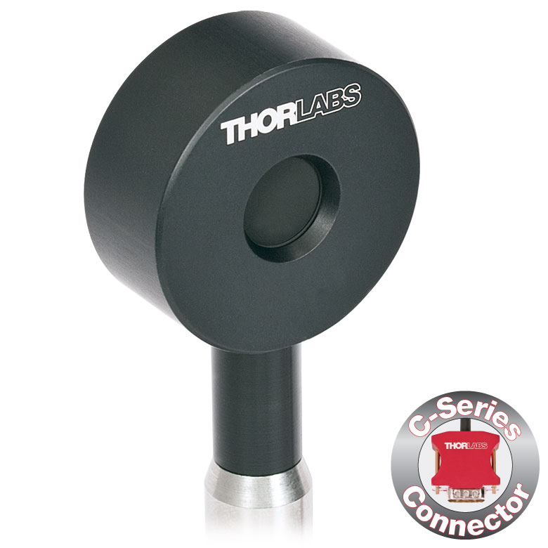 |
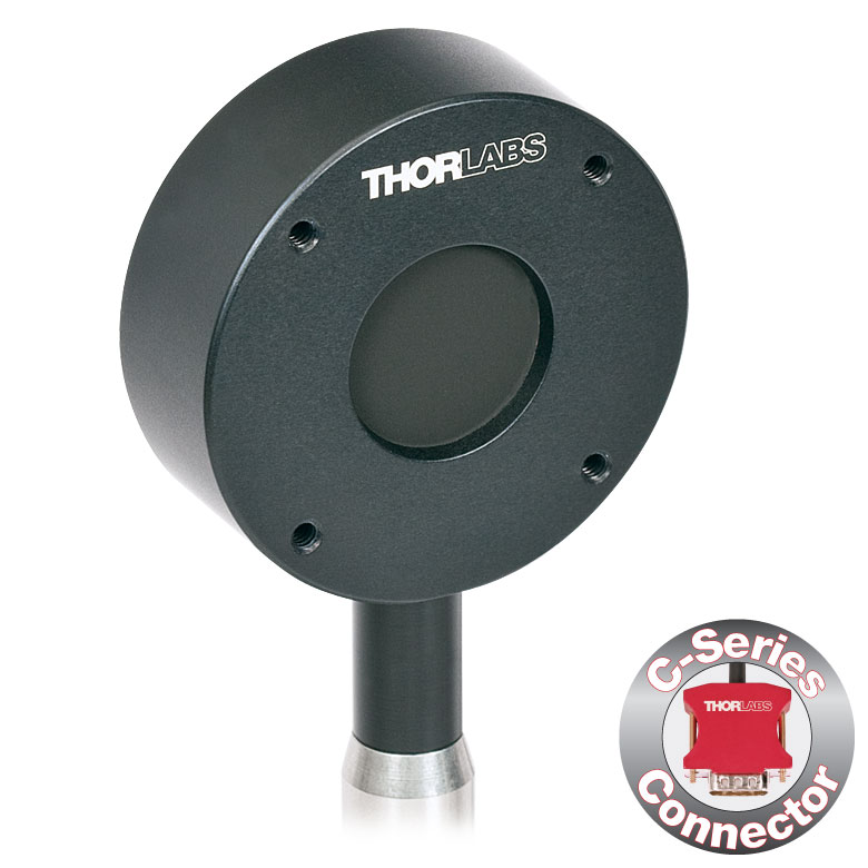 |
 |
 |
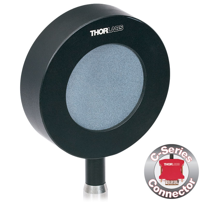 |
| Aperture Size | Ø11 mm | Ø20 mm | Ø45 mm | Ø20 mm | Ø45 mm |
| Wavelength Range | 0.185 - 25 µm | ||||
| Energy Range | 10 µJ - 150 mJ | 100 µJ - 500 mJ | 500 µJ - 2 J | 500 µJ - 3 J | 1 mJ - 15 J |
| Detector Type | Pyroelectric Energy Sensor with Black Broadband Coating | Pyroelectric Energy Sensor with Ceramic Coating | |||
| Resolution | 100 nJ | 1 µJ | 1 µJ | 25 µJ | 50 µJ |
| Linearity | ±1% | ||||
| Measurement Uncertainty | ±5% @ 0.185 - 25 µm | ||||
| Housing Dimensions | Ø36 mm x 16 mm | Ø50 mm x 18 mm | Ø75 mm x 21 mm | Ø50 mm x 18 mm | Ø75 mm x 21 mm |
| Cable Length | 1.5 m | ||||
| Post Mounting | 8-32 Mounting Thread, 8-32 and M4 Insulating Adapters Included | ||||
| Cage Mounting | N/A | Four 4-40 Taps for 30 mm Cage Systems |
N/A | Four 4-40 Taps for 30 mm Cage Systems |
N/A |
| Compatible Consoles | PM400, PM100D, and PM320E | ||||
| Compatible Interfaces | PM100USB | ||||
| Calibration Service Item # | Compatible Sensors |
|---|---|
| CAL1 | S120VC, S120C, S121C, S170C, S140C, S142C, S150C, S151C |
| CAL2 | S122C, S144C, S145C, S146C, S154C, S155C |
| CAL-S130 | S130VC, S130C |
| CAL-S132 | S132C |
| CAL4 | S148C, S180C |
Thorlabs offers calibration services for our photodiode optical power sensors and consoles. To ensure accurate measurements, we recommend recalibrating the sensors annually. Recalibration of the console is included with the recalibration of a sensor at no additional cost. If you wish to recalibrate only your power meter console, please contact Tech Support for details.
Refer to the table to the right for the appropriate calibration service Item # that corresponds to your power meter sensor. Once the appropriate Item # is selected, enter the Part # and Serial # of the sensor that requires recalibration prior to selecting Add to Cart.
| Sensor Type | Sensor Item #s |
|---|---|
| Thermal Power | S175C, S302Ca, S305Ca, S310Ca, S314Ca, S322C, S350C, S370C, S401C, S405C, S415C, S425C, S425C-L, S470C |
| Pyroelectric Energy | ES111C, ES120C, ES145C, ES220C, ES245C |
Thorlabs offers recalibration services for our thermal power and pyroelectric energy sensors. To ensure accurate measurements, we recommend recalibrating the sensors annually. Recalibration of the console is included with the recalibration of a sensor at no additional cost. If you wish to recalibrate only your power meter console, please contact Tech Support for details.
The table to the right lists the sensors for which this calibration service is available. Please enter the Part # and Serial # of the sensor that requires recalibration prior to selecting Add to Cart.