 Products Home / Electrophysiology / Rigid Stand Translation Stages / Translation Stages for Rigid Stands
Translation Stages for Rigid Stands

- Motorized Positioning of Rigid Stands
- 1" (25.4 mm) Travel in X and/or Y Axes
- Designed for Footprint of Our Rigid Stand Holders
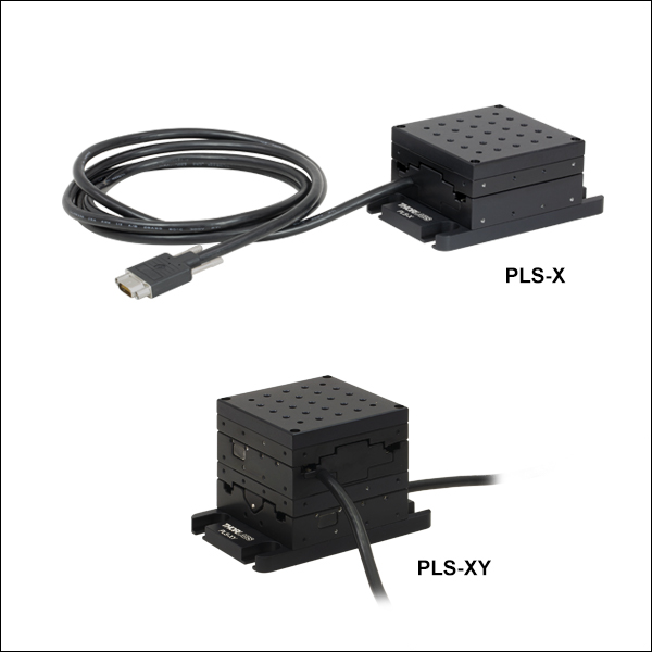
PLS-X
One-Axis Translation Stage
PLS-XY
Two-Axis Translation Stage
Rigid Stand Slide Holder on a PLS-XY Translation Stage


Please Wait
Thorlabs' 1D and 2D Stepper Motor Translation Stages are designed to be used with our line of Rigid Stands, which support slide holders, petri dishes, recording chambers, micromanipulators, and other samples that will be inserted into a Cerna® or other microscope's optical path. The stage mounts to the bottom of the rigid stand while maintaining the stand's compact footprint and can translate a load up to 42 lbs. This is ideal for space-constrained microscopy systems where a larger number of stands will need to be used. They are operated by our MCM3001 3-Axis Controller.
For our rigid stands, we also offer manual stages that provide 25 mm of translation in one or two horizontal axes. The manual stages with quick connect feature dovetails that allow users to construct their own multi-axis stage, while the self-contained manual stages offer a more compact footprint.

| Selection Guide for Rigid Stand Translation Stages | ||
|---|---|---|
 |
 |
 |
| Manual Stages with Quick Connect | Self-Contained Manual Stages | Motorized Stages |
Building a Cerna® Microscope
The Cerna microscopy platform's large working volume and system of dovetails make it straightforward to connect and position the components of the microscope. This flexibility enables simple and stable set up of a preconfigured microscope, and provides easy paths for later upgrades and modification. See below for a couple examples of the assembly of preconfigured and DIY Cerna microscopes.
Preconfigured Microscope Kit Design and Assembly
Walkthrough of Cerna® Microscope Kit 4
This Cerna microscope configuration is equipped with both epi- and trans-illumination modules. All Cerna preconfigured microscope kits enable individual components to be removed or substituted for complete customization.
The D1N and D2N circular dovetails align the sample viewing and epi-illumination apparatus along the optical path. The microscope body's 95 mm linear dovetail is used to secure the objective mounts and condenser mounts, as well as the transmitted light illumination module. The dovetail allows components to slide along the vertical rail prior to lockdown.
DIY Cerna Design and Assembly
Walkthrough of a DIY Microscope Configuration
This DIY microscope uses a CSA3000(/M) Breadboard Top, a CSA2001 Dovetail Adapter, our CSA1001 and CSA1002 Fixed Arms, and other body attachments and extensions. These components provide interfaces to our lens tube and cage construction systems, allowing the rig to incorporate two independent trans-illumination modules, a home-built epi-illumination path, and a custom sample viewing optical path.
DIY Microscope Configuration Assembly
The simplicity of Thorlabs optomechanical interfaces allows a custom DIY microscope to be quickly assembled and reconfigured for custom imaging applications.
The Cerna Mind Map is a visual tool that contains the complete selection of DIY Cerna components and several closely related accessories. Created as a supplement to our website, we have designed it to be printed on a single 11" x 17" sheet.
Click here or on the image below to download a printable PDF. The components shown on this webpage are in Step 10 of the mind map.

| Posted Comments: | |
Esmeralda Fonseca
(posted 2020-02-05 16:01:05.933) Hi!
I am interested in getting a motorized stage that allows me to position a black plastic square just in the middle of a mouse face. This black plastic square will have 4 needles coming out of it, two on the left and two on the right. One pair of needles will be more medial (to deliver water as a reward) and two needles will be more lateral to deliver air-puffs to the mouse whiskers. In order to permit the symmetrical delivery of the air puffs, we will need to adjust the position of the needles in XYZ axis (anteroposterior, lateromedial and dorsoventral). It is preferable that this is motorized and not manual. This motorized stage will be placed on a MB3030/M. Which suggestions do you have? If you have any spanish-speaker it would be helpful. Thanks a lot! YLohia
(posted 2020-03-11 05:00:48.0) Hello Esmeralda, thank you for contacting Thorlabs. A Spanish-speaking applications engineer reached out to you directly at the time of your original post. If you have further questions regarding this, please feel free to call us or reply to our direct conversation. |
Click on the different parts of the microscope to explore their functions.

Elements of a Microscope
This overview was developed to provide a general understanding of a Cerna® microscope. Click on the different portions of the microscope graphic to the right or use the links below to learn how a Cerna microscope visualizes a sample.
Terminology
Arm: Holds components in the optical path of the microscope.
Bayonet Mount: A form of mechanical attachment with tabs on the male end that fit into L-shaped slots on the female end.
Bellows: A tube with accordion-shaped rubber sides for a flexible, light-tight extension between the microscope body and the objective.
Breadboard: A flat structure with regularly spaced tapped holes for DIY construction.
Dovetail: A form of mechanical attachment for many microscopy components. A linear dovetail allows flexible positioning along one dimension before being locked down, while a circular dovetail secures the component in one position. See the Microscope Dovetails tab or here for details.
Epi-Illumination: Illumination on the same side of the sample as the viewing apparatus. Epi-fluorescence, reflected light, and confocal microscopy are some examples of imaging modalities that utilize epi-illumination.
Filter Cube: A cube that holds filters and other optical elements at the correct orientations for microscopy. For example, filter cubes are essential for fluorescence microscopy and reflected light microscopy.
Köhler Illumination: A method of illumination that utilizes various optical elements to defocus and flatten the intensity of light across the field of view in the sample plane. A condenser and light collimator are necessary for this technique.
Nosepiece: A type of arm used to hold the microscope objective in the optical path of the microscope.
Optical Path: The path light follows through the microscope.
Rail Height: The height of the support rail of the microscope body.
Throat Depth: The distance from the vertical portion of the optical path to the edge of the support rail of the microscope body. The size of the throat depth, along with the working height, determine the working space available for microscopy.
Trans-Illumination: Illumination on the opposite side of the sample as the viewing apparatus. Brightfield, differential interference contrast (DIC), Dodt gradient contrast, and darkfield microscopy are some examples of imaging modalities that utilize trans-illumination.
Working Height: The height of the support rail of the microscope body plus the height of the base. The size of the working height, along with the throat depth, determine the working space available for microscopy.
 Click to Enlarge
Cerna Microscope Body

Click to Enlarge
Body Details
Microscope Body
The microscope body provides the foundation of any Cerna microscope. The support rail utilizes 95 mm rails machined to a high angular tolerance to ensure an aligned optical path and perpendicularity with the optical table. The support rail height chosen (350 - 600 mm) determines the vertical range available for experiments and microscopy components. The 7.74" throat depth, or distance from the optical path to the support rail, provides a large working space for experiments. Components attach to the body by way of either a linear dovetail on the support rail, or a circular dovetail on the epi-illumination arm (on certain models). Please see the Microscope Dovetails tab or here for further details.
 Click to Enlarge
Illumination with a Cerna microscope can come from above (yellow) or below (orange). Illumination sources (green) attach to either.
Illumination
Using the Cerna microscope body, a sample can be illuminated in two directions: from above (epi-illumination, see yellow components to the right) or from below (trans-illumination, see orange components to the right).
Epi-illumination illuminates on the same side of the sample as the viewing apparatus; therefore, the light from the illumination source (green) and the light from the sample plane share a portion of the optical path. It is used in fluorescence, confocal, and reflected light microscopy. Epi-illumination modules, which direct and condition light along the optical path, are attached to the epi-illumination arm of the microscope body via a circular D1N dovetail (see the Microscope Dovetails tab or here for details). Multiple epi-illumination modules are available, as well as breadboard tops, which have regularly spaced tapped holes for custom designs.
Trans-illumination illuminates from the opposite side of the sample as the viewing apparatus. Example imaging modalities include brightfield, differential interference contrast (DIC), Dodt gradient contrast, oblique, and darkfield microscopy. Trans-illumination modules, which condition light (on certain models) and direct it along the optical path, are attached to the support rail of the microscope body via a linear dovetail (see Microscope Dovetails tab or here). Please note that certain imaging modalities will require additional optics to alter the properties of the beam; these optics may be easily incorporated in the optical path via lens tubes and cage systems. In addition, Thorlabs offers condensers, which reshape input collimated light to help create optimal Köhler illumination. These attach to a mounting arm, which holds the condenser at the throat depth, or the distance from the optical path to the support rail. The arm attaches to a focusing module, used for aligning the condenser with respect to the sample and trans-illumination module.
 |
 |
 |
 |
 |
 |
 |
 |
| Epi-Illumination Modules | Breadboards & Body Attachments |
Brightfield | DIC | Dodt | Condensers | Condenser Mounting | Light Sources |
 Click to Enlarge
Light from the sample plane is collected through an objective (blue) and viewed using trinocs or other optical ports (pink).
Sample Viewing/Recording
Once illuminated, examining a sample with a microscope requires both focusing on the sample plane (see blue components to the right) and visualizing the resulting image (see pink components).
A microscope objective collects and magnifies light from the sample plane for imaging. On the Cerna microscope, the objective is threaded onto a nosepiece, which holds the objective at the throat depth, or the distance from the optical path to the support rail of the microscope body. This nosepiece is secured to a motorized focusing module, used for focusing the objective as well as for moving it out of the way for sample handling. To ensure a light-tight path from the objective, the microscope body comes with a bellows (not pictured).
Various modules are available for sample viewing and data collection. Trinoculars have three points of vision to view the sample directly as well as with a camera. Double camera ports redirect or split the optical path among two viewing channels. Camera tubes increase or decrease the image magnification. For data collection, Thorlabs offers both cameras and photomultiplier tubes (PMTs), the latter being necessary to detect fluorescence signals for confocal microscopy. Breadboard tops provide functionality for custom-designed data collection setups. Modules are attached to the microscope body via a circular dovetail (see the Microscope Dovetails tab or here for details).


 Click to Enlarge
The rigid stand (purple) pictured is one of various sample mounting options available.
Sample/Experiment Mounting
Various sample and equipment mounting options are available to take advantage of the large working space of this microscope system. Large samples and ancillary equipment can be mounted via mounting platforms, which fit around the microscope body and utilize a breadboard design with regularly spaced tapped through holes. Small samples can be mounted on rigid stands (for example, see the purple component to the right), which have holders for different methods of sample preparation and data collection, such as slides, well plates, and petri dishes. For more traditional sample mounting, slides can also be mounted directly onto the microscope body via a manual XY stage. The rigid stands can translate by way of motorized stages (sold separately), while the mounting platforms contain built-in mechanics for motorized or manual translation. Rigid stands can also be mounted on top of the mounting platforms for independent and synchronized movement of multiple instruments, if you are interested in performing experiments simultaneously during microscopy.
 |
 |
 |
 |
 |
| Translating Platforms | Rigid Stands | Translation Stages for Rigid Stands | Motorized XY Stages | Manual XY Stage |
For sample viewing, Thorlabs offers trinoculars, double camera ports, and camera tubes. Light from the sample plane can be collected via cameras, photomultiplier tubes (PMTs), or custom setups using breadboard tops. Click here for additional information about viewing samples with a Cerna microscope.
| Product Families & Web Presentations | |||
 |
|
 |
 |
| Sample Viewing | Breadboards & Body Attachments |
Cameras | PMTs |
Microscope objectives are held in the optical path of the microscope via a nosepiece. Click here for additional information about viewing a sample with a Cerna microscope.
| Product Families & Web Presentations | ||||
 |
 |
 |
 |
 |
| Objectives | Objective Thread Adapters | Parfocal Length Extender | Piezo Objective Scanner | Objective Mounting |
Large and small experiment mounting options are available to take advantage of the large working space of this microscope. Click here for additional information about mounting a sample for microscopy.
| Product Families & Web Presentations | ||||
|
|
|
|
 |
| Translating Platforms | Rigid Stands | Translation Stages for Rigid Stands | Motorized XY Stages | Manual XY Stage |
Thorlabs offers various light sources for epi- and trans-illumination. Please see the full web presentation of each to determine its functionality within the Cerna microscopy platform.
| Product Families & Web Presentations | ||||
 |
 |
 |
 |
|
| Trans-Illumination Kits | Solis™ High-Power LEDs | Mounted LEDs | X-Cite® Lamps | Other Light Sources |
Epi-illumination illuminates the sample on the same side as the viewing apparatus. Example imaging modalities include fluorescence, confocal, and reflected light microscopy. Click here for additional information on epi-illumination with Cerna.
| Product Families & Web Presentations | ||
|
|
|
| Epi-Illumination | Body Attachments | Light Sources |
Trans-illumination illuminates from the opposite side of the sample as the viewing apparatus. Example imaging modalities include brightfield, differential interference contrast (DIC), Dodt gradient contrast, oblique, and darkfield microscopy. Click here for additional information on trans-illumination with Cerna.
| Product Families & Web Presentations | ||||||
|
|
|
|
 |
|
|
| Brightfield | DIC | Dodt | Condensers | Condenser Mounting | Illumination Kits | Other Light Sources |
The microscope body provides the foundation of any Cerna microscope. The 7.74" throat depth provides a large working space for experiments. Click here for additional information about the Cerna microscope body.
| Product Families & Web Presentations | |
 |
 |
| Microscope Bodies | Microscope Translator |

 Zoom
Zoom
Click to Enlarge
PLS-XY Being Used to Translate a Rigid Stand Slide Holder in a Cerna Microscope System

Click for Details
Drawing of Translation Stage
- Fine Motorized Movement for Rigid Stands
- High Load Capacities with Compact Footprint
- One or Two Axes of Travel:
- PLS-X: One-Axis Translation Stage
- PLS-XY: Two-Axis Translation Stage
These stepper motor translation stages are designed for use with our rigid stand slide holders, petri dish holders, recording chamber holders, platforms, and post holders. The PLS-X provides linear travel along one axis, while the PLS-XY provides linear travel along two axes. It is possible to combine two PLS-X stages to effectively create a PLS-XY stage, leaving open the possibility of later upgrades.
Each stage includes a 3.00" x 4.50" (76.2 mm x 114.3 mm) base plate that contains four 1/4" (M6) counterbored slots for securing the stage to the workstation. The top plate offers four M3 counterbores that are used to mate the translation stage directly to one of our rigid stands (see Installation section below), as well as twenty-one 8-32 taps at 0.50" spacings for custom mounting needs.
The PLS-X adds 1.48" (37.6 mm) of fixed height to the rigid stand, while the PLS-XY adds 2.57" (65.3 mm) of fixed height to the rigid stand. Each permanently attached motor cable is 6' (1.8 m) long.
We also offer manual translation stages that are compatible with our rigid stands by using the MPA1(/M) adapter plate.
Installation
To mount a rigid stand to the top of the translation stage, detach the base plate that came with the rigid stand from the red post holder by using a 2.5 mm balldriver to remove the four M3 cap screws. This base plate will be replaced by the motorized translation stage. Next, detach the top plate of the translation stage by using a 3/32" balldriver to remove the four 4-40 cap screws at the corners. This top plate contains four M3 counterbores that are spaced to mate with the end of the red post holder.
| Stage Specifications | |||
|---|---|---|---|
| Item # | PLS-X | PLS-XY | |
| Axes of Travel | One | Two | |
| Travel Range | 1" (25.4 mm) | ||
| Bidirectional Repeatability | 1 µm | ||
| Backlash | 1 µm | ||
| Minimum Achievable Incremental Movement | 100 nm | ||
| Minimum Repeatable Incremental Movement | 200 nm | ||
| Velocity (Max) | 7 mm/s | ||
| Acceleration (Max) | 11 mm/s2 | ||
| Load Capacity | |||
| Stage Mounted Horizontally | Recommended | ≤33.5 lbs (15.2 kg) | ≤32.4 lbs (14.7 kg) |
| Maximum | 42 lbs (19.1 kg) | 41 lbs (18.6 kg) | |
| Stage Mounted Vertically | Recommended | ≤10 lbs (4.5 kg) | ≤8.8 lbs (4.0 kg) |
| Maximum | 10 lbs (4.5 kg) | 8.8 lbs (4.0 kg) | |
| Stepper Motor Specifications | |
|---|---|
| Cable Length | 6' (1.8 m) |
| Thread Screw Pitch |
0.3 mm |
| Step Angle | 1.8° |
| Limit Switches | Hall Effect Sensors |
| Phase Current | 0.49 A |
| Phase Resistance | 5.1 Ω |
| Phase Inductance | 1.5 mH |
| Insulation Resistance | 20 MΩ |

 Zoom
Zoom| Compatible Stages | |
|---|---|
| Motorized Focusing Modules | |
| Translation Stages for Rigid Stands |
| Controller Specifications |
|---|
| Compatible Motor Specifications |
|---|
- Designed for Cerna Components with 1" Motorized Travel
- Knobs Provide Hand-Operated Control for up to Three Axes
- Each Axis can be Individually Disabled to Prevent
Unintended Movements or to Retain a Position - Adjust Translation Speed via Top-Located Knob
The MCM3001 3-Axis Controller consists of a hand-operated knob box and a separate controller, as shown in the photo to the right. Each side face of the knob box includes a rotating knob and a push-button switch that are dedicated to a single axis. The push-button switch enables and disables the axis, and is lit in green when the axis is enabled. Disabling the axis lets the user preserve a position or prevent accidental movements. A smaller knob on the top face adjusts the amount of translation per rotation of the knob (see the Controller Specifications table for details).
Since each MCM3001 controller has three channels, you only need to purchase enough channels for each of the modules you intend to drive. For example, a Cerna microscope equipped with a ZFM2020 Motorized Focusing Module (which has one axis) and a PLS-XY Translation Stage (two axes) would only require one MCM3001 controller.
The MCM3001 is compatible with motorized Cerna components that have a travel range of 1", such as our Motorized Focusing Modules and Translation Stages for Rigid Stands; see the Compatible Motor Specifications table for use with alternate motorized products. For components with a 2" travel range, such as our Translating Platforms, the MCM3002 controller should be used instead. If you would like a controller configured to drive more than one type of stage, please contact Tech Support.
SDK and LabVIEW examples are also available by contacting Tech Support.