 Products Home / Detectors / Balanced Detectors / Balanced Amplified Photodetectors with Fast Monitor Output
Balanced Amplified Photodetectors with Fast Monitor Output
- Models Available with Bandwidths up to 2.5 GHz
- Noise Cancellation by Subtraction of 2 Input Signals
- >20 dB Common Mode Rejection Ratio
- Fast Monitor Outputs
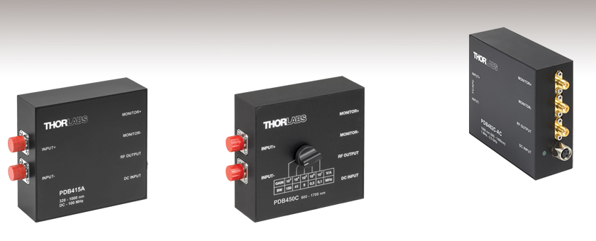
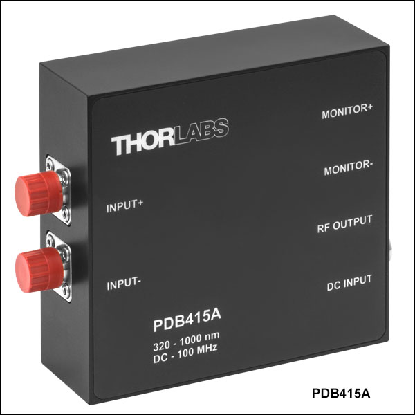
PDB415A
Fixed Gain, 100 MHz, Si
Optical Inputs Shown
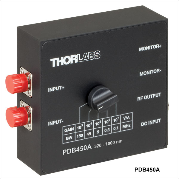
PDB450C
Switchable Gain, InGaAs
Optical Inputs Shown
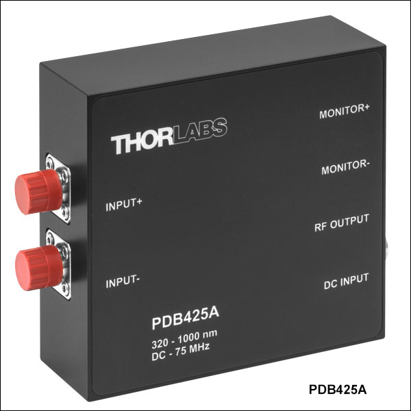
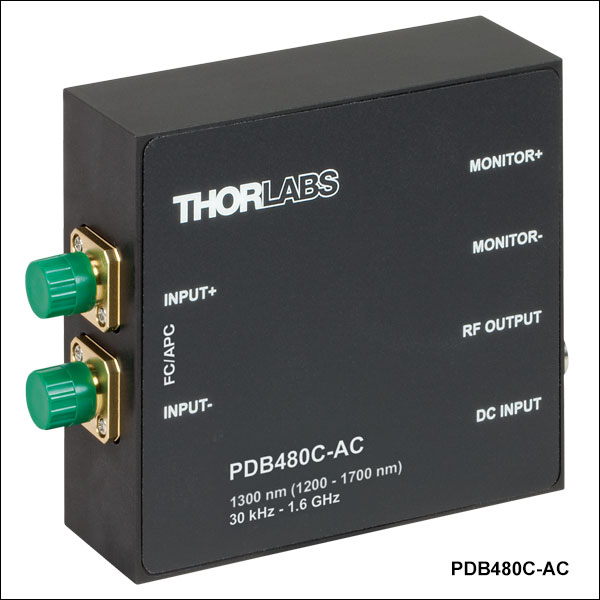
PDB482C-AC
Fixed Gain, 2.5 GHz, InGaAs, AC Coupled
Electrical Outputs Shown


Please Wait
| Balanced Detector Selection Guide |
|---|
| Balanced Detectors with Fast Monitor Output |
| Large-Area Balanced Amplified Detectors |
| Suitable for OCT |
| Compact Balanced Amplified Detectors |
| Compact 5 GHz Balanced Detectors |
| OCT Balanced Detectors with Fast Monitor Output |
| Auto-Balanced Detector with Avalanche Photodiodes |
| Polarization-Dependent Balanced Detector |
Typical Applications
- Spectroscopy
- Heterodyne Detection
- Optical Coherence Tomography OCT
- Optical Delay Measurements
- THz Detection
| Balanced Detector with Fast Monitor Output | |||
|---|---|---|---|
| Bandwidth | Available Wavelength Ranges |
Fast Monitor Output Bandwidth |
Gain |
| Switchable (DC - 0.1, 0.3, 4, 45, or 150 MHz) |
320 to 1000 nm or 800 - 1700 nm |
DC - 1 MHz | Switchable |
| DC - 15 MHz | Fixed | ||
| DC - 75 MHz | |||
| DC - 100 MHz | |||
| DC - 200 MHz | |||
| DC - 350 MHz | |||
| DC - 400 MHz | Optimized for 1060 nm (900 - 1400 nm Range) or Optimized for 1300 nm (1200 - 1700 nm Range) |
DC - 3 MHz | |
| 30 kHz - 1.0 GHz | Optimized for 1060 nm (900 - 1400 nm Range) |
||
| 30 kHz - 1.6 GHz | Optimized for 1300 nm (1200 - 1700 nm Range) |
||
| 1 MHz - 2.5 GHz | Optimized for 1060 nm (900 - 1400 nm Range) |
DC - 2.5 MHz | |
Features
- Four Wavelength Ranges Available
- 320 - 1000 nm
- 800 - 1700 nm
- 900 - 1400 nm (Optimized for 1060 nm)
- 1200 - 1700 nm (Optimized for 1300 nm)
- >20 dB Common Mode Rejection Ratio
- Fast Monitor Outputs
- Choose a Si or InGaAs Detector
- FC Fiber Inputs Available in All Versions
- Free Space Inputs Available on Some Detectors (See Below for Details)
- Switchable Power Supply Included
- Switchable Transimpedance Gain Version Available
These balanced photodetectors act as a balanced receiver by subtracting the two optical input signals from each other, resulting in the cancellation of common mode noise. This allows small changes in the signal path to be extracted from the interfering noise floor.
The detectors consist of two balanced photodiodes and an ultra-low-noise, high-speed transimpedance amplifier. The two photodiodes are matched to achieve an excellent common mode rejection ratio (CMRR), leading to better noise reduction. Please see the Operation tab for more details. All of these detectors incorporate three female SMA electrical ports for reduced noise. In addition to the RF-output from the transimpedance amplifier, the Monitor+ and Monitor- ports allow the response of each photodiode to be observed individually.
To block the CW component (the unmodulated part) of the optical input signal, an AC-coupled version of each detector is offered. Note that the PDB480C-AC, PDB481C-AC, and PDB482C-AC are only available AC coupled. This improves the ability to measure a comparably weak, frequency-modulated signal over a strong CW background signal that could saturate the amplifier. The lower cut-off frequency for the AC-coupled versions, with exception to the PDB480C-AC, PDB481C-AC, and PDB482C-AC, is guaranteed to be ≤100 Hz, but will typically be below 5 Hz.
Bandwidths of DC - 350 MHz or Lower
Detectors with bandwidths of DC - 350 MHz or lower are available with either Si or InGaAs photodiodes for the 320 - 1000 nm or 800 - 1700 nm range, respectively. The inputs on these detectors are not fiber coupled to the photodiodes and come with two removable FC input connectors, making them suitable for either free space or fiber applications. Although the PDB465 and PDB435 detectors also contain non-fiber-coupled sensors, the FC/PC adapters at the inputs cannot be removed.
Bandwidths of DC - 400 MHz or Higher
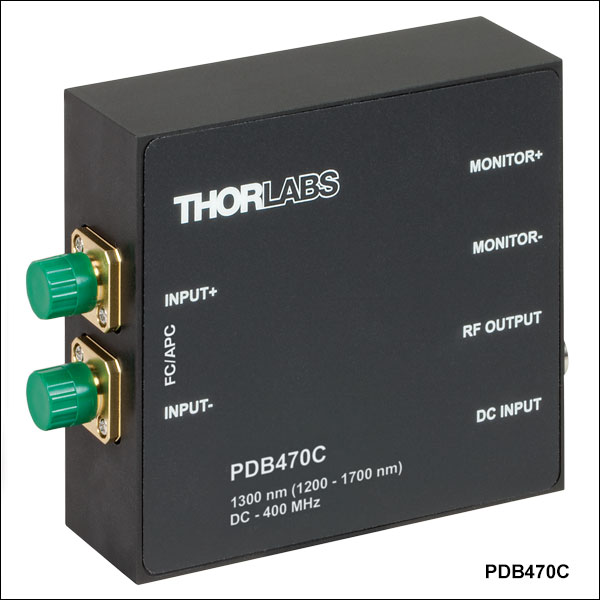
Detectors with bandwidths of DC - 400 MHz or higher feature fiber-coupled photodiodes connected to FC/APC optical inputs with exactly length-matched SMF-28e+ or HI1060 fiber to achieve excellent CMRR values across the full detector bandwidth. All of these detectors incorporate InGaAs photodiodes and are optimized for either 1060 nm (900 - 1400 nm range) or 1300 nm (1200 - 1700 nm range). The fiber-coupled design suppresses line artifacts in the OCT image, which generally occur when detector coupling optics are used.
Our highest bandwidth balanced detectors (PDB480C-AC, PDB481C-AC, and PDB482C-AC) are offered in an AC version only. They offer bandwidths up to 2.5 GHz, leading to considerable speed improvements. The ultra-low-distortion output stage supports up to a 2 Vp-p A/D card input range, which, combined with the fiber-coupled design, improves the image quality for OCT applications considerably.
Packaging/Power Supply
Housed in a shielded aluminum enclosure measuring 85 mm x 80 mm x 30 mm, these detectors are post mountable using the included adapter plate, which can be attached to the bottom or side of the housing with the included M2 screws. The unit is powered with the provided ±12 V DC power supply, for which a replacement is available below.
Thorlabs also offers Fiber-Based Interferometers, which feature an integrated balanced detector. If you are primarily interested in using our balanced detectors with OCT systems, a condensed list of detectors suitable for this application can be found here.
| Item # | PDB415A(-AC) | PDB415C(-AC) | PDB425A(-AC) | PDB425C(-AC) | PDB435A(-AC) | PDB435C(-AC) |
|---|---|---|---|---|---|---|
| Detector Type | Si/PIN | InGaAs/PIN | Si/PIN | InGaAs/PIN | Si/PIN | InGaAs/PIN |
| Wavelength Range | 320 - 1000 nm | 800 - 1700 nm | 320 - 1000 nm | 800 - 1700 nm | 320 - 1000 nm | 800 - 1700 nm |
| Max Responsivity (Typical) | 0.53 A/W | 1.0 A/W | 0.53 A/W | 1.0 A/W | 0.50 A/W | 1.0 A/W |
| Active Detector Diameter | 0.8 mm | 0.3 mm | 0.8 mm | 0.3 mm | 0.4 mm | 0.15 mm |
| Bandwidth (3 dB) | DC - 100 MHz AC Coupled (-AC Suffix): 100 Hz - 100 MHz |
DC - 75 MHz AC Coupled (-AC Suffix): 100 Hz - 75 MHz |
DC - 350 MHz AC Coupled (-AC Suffix): 100 Hz - 350 MHz |
|||
| Common Mode Rejection Ratio | >25 dB | >35 dB | >20 dB | |||
| Transimpedance Gaina | 50 x 103 V/A | 250 x 103 V/A | 10 x 103 V/A | |||
| Minimum NEPb | 12.03 pW/Hz1/2 (DC - 100 MHz) |
6.99 pW/Hz1/2 (DC - 100 MHz) |
9.5 pW/Hz1/2 (DC - 75 MHz) |
5.2 pW/Hz1/2 (DC - 75 MHz) |
32.3 pW/Hz1/2 (DC - 350 MHz) |
15.28 pW/Hz1/2 (DC - 350 MHz) |
| RF Output | ||||||
| Conversion Gain RF Outputa,c | 26.5 x 10³ V/W | 50 x 103 V/W | 133 x 103 V/W | 250 x 103 V/W | 5 x 10³ V/W | 10 x 103 V/W |
| CW Saturation Power RF Output | 135 µW @ 820 nm | 72 µW @ 1550 nm | 27 µW @ 820 nm | 15 µW @ 1550 nm | 720 µW @ 820 nm | 360 µW @ 1550 nm |
| Impedance | 50 Ω | |||||
| Max Voltage Swing | ±1.8 V for 50 Ω Load ±3.6 V for High-Impedance Load |
|||||
| DC Offset | < ±3 mV | |||||
| RF-Output Coupling | DC or AC | |||||
| Monitor Outputs | ||||||
| Conversion Gain Monitor Outputs | 10 V/mW @ 820 nm | 10 V/mW @ 1550 nm | 10 V/mW @ 820 nm | 10 V/mW @ 1550 nm | 10 V/mW @ 820 nm | 10 V/mW @ 1550 nm |
| Impedance | 220 Ω | |||||
| Max Voltage Swing | 1.55 V for 50 Ω Load 10 V for High-Impedance Load |
|||||
| Bandwidth | DC to 1 MHz | |||||
| Voltage Noise | <180 µVRMS | |||||
| DC Offset | < ±2 mV | |||||
| General | ||||||
| Fiber Optical Inputsd | FC/PC or FC/APC (Removable) |
FC/PC or FC/APC (Not Removable) |
||||
| Photodiode Damage Threshold | 20 mW | |||||
| Electrical Outputs | SMA (Qty. 3) | |||||
| Dimensions | 85 mm x 80 mm x 30 mm (3.35" x 3.15" x 1.18") | |||||
| Weight | 0.35 kg (without Power Supply) | |||||
| Operating Temperature Rangee | 0 to 40 °C |
|||||
| Storage Temperature Range | -40 to 70 °C | |||||
| Included Power Supplyf | ±12 V @ 250 mA (100/120/230 VAC, 50 - 60 Hz, Switchable) |
|||||
| Item # | PDB440A(-AC) | PDB440C(-AC) | PDB450A(-AC) | PDB450C(-AC) | PDB465A(-AC) | PDB465C(-AC) |
|---|---|---|---|---|---|---|
| Detector Type | Si/PIN | InGaAs/PIN | Si/PIN | InGaAs/PIN | Si/PIN | InGaAs/PIN |
| Wavelength Range | 320 - 1000 nm | 800 - 1700 nm | 320 - 1000 nm | 800 - 1700 nm | 320 - 1000 nm | 800 - 1700 nm |
| Max Responsivity (Typical) | 0.53 A/W | 1.0 A/W | 0.53 A/W | 1.0 A/W | 0.50 A/W | 1.0 A/W |
| Active Detector Diameter | 0.8 mm | 0.3 mm | 0.8 mm | 0.3 mm | 0.8 mm | 0.15 mm |
| Bandwidth (3 dB) | DC - 15 MHz AC Coupled (-AC Suffix): 100 Hz - 15 MHz |
DC - 150, 45, 4, 0.3, 0.1 MHz AC Coupled (-AC Suffix): 100 Hz - 150, 45, 4, 0.3, 0.1 MHz |
DC - 200 MHz AC Coupled (-AC Suffix): 100 Hz - 200 MHz |
|||
| Common Mode Rejection Ratio | >35 dB | >25 dB | >25 dB | |||
| Transimpedance Gaina | 51 x 103 V/A | 103, 104, 105, 106, 107 V/A | 30 x 103 V/A | |||
| Minimum NEPb | 6.9 pW/Hz1/2 (DC - 15 MHz) |
3.9 pW/Hz1/2 (DC - 15 MHz) |
DC - 0.1 MHz: 1.4 pW/Hz1/2 DC - 0.3 MHz: 1.1 pW/Hz1/2 DC - 4.0 MHz: 3.3 pW/Hz1/2 DC - 45 MHz: 28.9 pW/Hz1/2 DC - 150 MHz: 123 pW/Hz1/2 |
DC - 0.1 MHz: 0.7 pW/Hz1/2 DC - 0.3 MHz: 0.5 pW/Hz1/2 DC - 4.0 MHz: 1.55 pW/Hz1/2 DC - 45 MHz: 14.9 pW/Hz1/2 DC - 150 MHz: 68.6 pW/Hz1/2 |
22.86 pW/Hz1/2 (DC - 200 MHz) |
8.52 pW/Hz1/2 (DC - 200 MHz) |
| RF Output | ||||||
| Conversion Gain RF Outputa,c | 27 x 103 V/W | 51 x 103 V/W | 0.53 x 10³ V/W, 0.53 x 10⁴ V/W, 0.53 x 10⁵ V/W, 0.53 x 10⁶ V/W, 0.53 x 10⁷ V/W |
103 V/W, 104 V/W, 105 V/W, 106 V/W, 107 V/W |
16 x 103 V/W | 30 x 103 V/W |
| CW Saturation Power RF Output | 130 µW @ 820 nm | 70 µW @ 1550 nm | 9 mW @ 820 nm | 4.5 mW @ 1550 nm | 225 µW @ 820 nm | 120 µW @ 1550 nm |
| Impedance | 50 Ω | |||||
| Max Voltage Swing | ±1.8 for 50 Ω Load ±3.6 V for High-Impedance Load |
±4.6 V (103 to 106 Gain)a ±10 V (107 Gain)a |
±1.8 for 50 Ω Load ±3.6 V for High-Impedance Load |
|||
| DC Offset | < ±3 mV | < ±15 mV | < ±3 mV | |||
| RF-Output Coupling | DC or AC | |||||
| Monitor Outputs | ||||||
| Conversion Gain Monitor Outputs | 10 V/mW @ 820 nm | 10 V/mW @ 1550 nm | 10 V/mW @ 820 nm | 10 V/mW @ 1550 nm | 10 V/mW @ 820 nm | 10 V/mW @ 1550 nm |
| Impedance | 220 Ω | |||||
| Max Voltage Swing | 1.55 V for 50 Ω Load 10 V for High-Impedance Load |
|||||
| Bandwidth | DC to 1 MHz | |||||
| Voltage Noise | <180 µVRMS | |||||
| DC Offset | < ±2 mV | |||||
| General | ||||||
| Fiber Optical Inputsd | FC/PC or FC/APC (Removable) |
FC/PC or FC/APC (Not Removable) |
||||
| Photodiode Damage Threshold | 20 mW | |||||
| Electrical Outputs | SMA (Qty. 3) | |||||
| Dimensions | 85 mm x 80 mm x 30 mm (3.35" x 3.15" x 1.18") | |||||
| Weight | 0.35 kg (without Power Supply) | |||||
| Operating Temperature Rangee | 0 to 40 °C |
|||||
| Storage Temperature Range | -40 to 70 °C | |||||
| Included Power Supplyf | ±12 V @ 250 mA (100/120/230 VAC, 50 - 60 Hz, Switchable) |
|||||
| Item # | PDB470C(-AC)a | PDB471C(-AC)a | PDB480C-ACa | PDB481C-ACa | PDB482C-ACa |
|---|---|---|---|---|---|
| Detector | |||||
| Detector Type | InGaAs/PIN | ||||
| Optical Inputs | FC/APC | ||||
| Internal Coupling Fiber | SMF-28e+ | HI1060 | SMF-28e+ | HI1060 | |
| Coupling Loss | <0.5 dB (<0.3 dB Typ.) | <1.0 dB (<0.4 dB Typ.) | <0.5 dB (<0.3 dB Typ.) | <1.0 dB (<0.4 dB Typ.) | |
| Operating Wavelength | Optimized for 1300 nm (1200 - 1700 nm Range) |
Optimized for 1060 nm (900 - 1400 nm Range) |
Optimized for 1300 nm (1200 - 1700 nm Range) |
Optimized for 1060 nm (900 - 1400 nm Range) |
|
| Responsivity (Typical) | 0.85 A/W @ 1300 nm | 0.72 A/W @ 1060 nm | 0.85 A/W @ 1300 nm | 0.72 A/W @ 1060 nm | |
| Active Detector Diameter | 0.075 mm | 0.080 mm | 0.075 mm | 0.080 mm | |
| Optical Back Reflection | <-40 dB | ||||
| Photodiode Damage Threshold | 10 mW | 5 mW | 10 mW | 5 mW | |
| RF OUTPUT | |||||
| RF OUTPUT Bandwidth (3 dB) | DC - 400 MHz AC Coupled (-AC Suffix): 100 Hz - 400 MHz |
30 kHz - 1.6 GHz | 30 kHz - 1.0 GHz | 1 MHz - 2.5 GHz | |
| Common Mode Rejection Ratio | >25 dB (Typ. >30 dB) | >20 dB (Typ. >25 dB) | |||
| RF OUTPUT Transimpedance Gain | 10 x 103 V/Ab | 16 x 103 V/Ac | 28 x 103 V/Ac | ||
| RF OUTPUT Conversion Gain | 9 x 10³ V/W @ 1300 nmb | 7.2 x 10³ V/W @ 1060 nmb | 14.4 x 10³ V/W @ 1300 nmc | 11.5 x 10³ V/W @ 1060 nmc | 20 x 103 V/W @ 1060 nmc |
| RF OUTPUT Power at 1 dB Compressionc | - | +16.5 dBm Min +18 dBm Typ. |
|||
| RF OUTPUT CW Saturation Power | 420 µW @ 1300 nm | 530 µW @ 1060 nm | See Note Below | ||
| RF OUTPUT Coupling | DC or AC | AC Coupling Only | |||
| RF OUTPUT Impedance | 50 Ω | ||||
| Max Voltage Swing | ±1.9 V for 50 Ω Load ±3.8 V for High-Impedance Load |
See Note Below | |||
| Minimum NEPd | 8 pW/Hz1/2 (DC to 100 MHz) |
9.3 pW/Hz1/2 (30 kHz to 100 MHz) |
9.0 pW/Hz1/2 (30 kHz to 100 MHz) |
12.0 pW/Hz1/2 (1 MHz to 100 MHz) |
|
| Overall Output Voltage Noise | <2.0 mVRMS | <9 mVRMS | <6.5 mVRMS | <12 mVRMS | |
| MONITOR Outputs | |||||
| MONITOR Output Impedance | 200 Ω | ||||
| MONITOR Output Bandwidth (3 dB) | DC - 3 MHz | DC - 2.5 MHz | |||
| MONITOR Output Conversion Gain, High Z Loadb |
9 V/mW @ 1300 nm | 7.2 V/mW @ 1060 nm | 9 V/mW @ 1300 nm | 7.2 V/mW @ 1060 nm | |
| MONITOR Output Voltage Swing, High Z Load | 10 V Max | ||||
| Overall Output Voltage Noise | <0.65 mVRMS | ||||
| DC Offset | < ±2 mV | ||||
| General | |||||
| Electrical Outputs | SMA | ||||
| Included DC Power Supplye | ±12 V @ 250 mA (100/120/230 VAC, 50 - 60 Hz, Switchable) |
||||
| Operating Temperature Rangef | 0 °C to 40 °C | ||||
| Storage Temperature Range | -40 °C to 70 °C | ||||
| Dimensions (W x H x D) | 85 mm x 80 mm x 30 mm (3.35" x 3.15" x 1.18") | ||||
| Weight | 0.35 kg | ||||
Note:
For the PDB480C-AC, PDB481C-AC, and PDB482C-AC detectors the RF output signal must not exceed the RF Output Power at 1 dB Compression, which is the point at which the amplified signal at 1 GHz is compressed by 1 dB. Above this value, the amplified signal will become non-linear and begin to saturate. The RF output voltage at this saturation point can be calculated using the following formula:
![]()
where R is the load impedance (50 Ω), P0 is defined as 1 mW, and L(dBm) is the power level in dBm. Using the specified RF Output Power at 1 dB Compression of 16.5 dBm, this yields the following "maximum" output voltage:

Operation of Balanced Detectors with Bandwidths up to 400 MHz
Thorlabs' Balanced Amplified Photodetectors consist of two well-matched photodiodes and an ultra-low noise, high-speed transimpedance amplifier (TIA) that generates an output voltage (RF OUTPUT) proportional to the difference between the photocurrents in the two photodiodes (i.e., the two optical input signals). Additionally, the unit has two fast monitor outputs (MONITOR+ and MONITOR-) to observe the optical input power levels on each photodiode separately. These outputs are low frequency outputs and cannot be used to measure an RF modulation on the signal. The block diagram applies to our balanced detectors with bandwidths up to 400 MHz.

Operation of the PDB480C-AC, PDB481C-AC, and PDB482C-AC Balanced Detectors
The PDB48xC-AC Balanced Amplified Photodetectors use the same basic operating principles as described above and have the following additional features. The TIA's ultra-low distortion output stage supports up to a 2 Vp-p A/D card input range. The two fast monitor outputs can be used to measure not only the individual optical input power levels, but also low frequency modulated signals up to 3 MHz (Item #s PDB480C-AC and PDB481C-AC) or 2.5 MHz (Item # PDB482C-AC). To enable the much higher frequency of these detectors, the photodiodes are connected to the inputs with length-matched fibers, only AC-coupled versions are offered, and capacitors are added to the circuit (as shown below).

Pin Diagrams for Balanced Amplified Photodetectors
Monitor +/-
SMA Female

Maximum Voltage is +10 V for Hi-Z & +1.5 V into 50 Ω loads.
RF Output
SMA Female
For the PDB415, PDB425, PDB440, and PDB465 photodetectors, the maximum RF OUTPUT voltage is ±3.6 V for Hi-Z & ±1.8 V into 50 Ω loads.
The RF OUTPUT CW saturation power is 420 µW @ 1300 nm and 530 µW at 1060 nm for the PDB470C and PDB471C, respectively.
For the PDB48xC-AC photodetectors, the RF OUTPUT Power at 1 dB compression into 50 Ω loads is +16.5 dBm (Min), +18 dBm (Typical)
PDB Male (Power Cables)

PDB Female (Photodetector)

| Posted Comments: | |
Seth Erickson
(posted 2020-10-26 14:52:00.707) On the PDB415A, the two photodiodes are mounted 20 mm apart. While this is fine for fiber coupled operation, it creates a problem for free space coupling. Since we use 1 inch optics with 1/2" posts & post holders, it is actually impossible to get proper lens alignment, since having the center of the lenses 20 mm apart results in overlapping lenses. Since this is a common lab setup, it seems silly that the photodiodes are 20 mm apart instead of 30-35 mm, which would provide 5-10 mm separation between lenses, allowing room for pedestal mounting. Might be a silly nitpick, but thought you might appreciate the feedback. Cheers MKiess
(posted 2020-10-27 10:26:35.0) Dear Seth, Thank you very much for this feedback. This is not a silly nitpick. Such feedback helps us to constantly improve our products. Even though the PDB415A is mainly designed for fiber applications, it is also suitable for free space applications due to the possible removal of the FC adapter. Therefore, it is correct that the distance is not ideal for a free space application with the standard sizes, 1/2" or 1" optics. Thank you very much for this information. For applications with larger optics the detector you can find under the following link would be more suitable:
https://www.thorlabs.de/newgrouppage9.cfm?objectgroup_id=1299&pn=PDB210A Qiangzhou Rong
(posted 2020-06-17 09:13:10.84) Dear Mr/Mrs/Miss,
I am postdoc at Duke University. We bought a PDB425C-AC detector recently. The noise from the RF port is larger than 100 mV without any light input. It is too large to be used in experiment. Is it correct or something rong in operation make it so large? Could you give me some comments as soon as possible? Urgently waiting for kind help! Thank you very much!
Best regards,
Qiangzhou Rong MKiess
(posted 2020-06-19 07:31:15.0) This is a response from Michael at Thorlabs. Thank you for the inquiry.A noise of more than 100mV is too high for this detector, if used properly. I have contacted you directly to discuss your application and find a solution together with you. wu nigel
(posted 2020-02-05 17:39:41.227) please tell me Balanced detector life MKiess
(posted 2020-02-06 06:18:35.0) This is a response from Micael at Thorlabs. Thank you for the inquiry. I have contacted you directly to discuss the influences on the lifetime of the detector in relation to your application. Kristof Reynkens
(posted 2019-06-27 05:02:47.707) I wondered if the PDB450A(-AC) can be cooled and how the NEP would change vs temperature. dpossin
(posted 2019-06-28 09:57:23.0) Hello Kristof,
Thank you for your Feedback. In general the NEP will decrease when you lower the temperature. The NEP with respect to wavelength can be calculated the following way: NEP(lambda)=(R_max/R(lambda))x NEP_min.
There R_max is the maximum responsivity, R(lambda) is the responsivity with respect to the wavelenght and NEP_min is the NEP value which is specified on the homepage.
The detector can be cooled but you will need to build up the cooling circuit yourself.
I will reach out directly to you to support you with temperature related data on the photodiode itself. Jonathan Doorn
(posted 2019-04-01 18:34:40.513) I am running some noise experiments with this device, the PDB450A, and I would like to know more about the noise characteristics of this device. What opamps does this device use? swick
(posted 2019-04-05 03:46:29.0) This is a response from Sebastian at Thorlabs. Thank you for the inquiry. In the manual we show graphs with typical spectral noise for PDB450A at each gain setting. I contacted you directly to provide further assistance. zenin
(posted 2019-02-20 10:03:49.533) Hi,
Currently I am using PDB450C and PDB450A-AC. I found that AC-coupled detection is better for my setup, so I am wondering, is it possible to upgrade my PDB450C to AC-coupled version? If yes, what is time scale and price?
Additionally, I would like to give you two proposals for making it better:
1) It would be nice to have a single device with on-off switch for AC-coupling. Then people like me would not make trials & errors on which one to buy.
2) The holder for post-mounting (with 4 holes to attach to detector) is rather disappointing. It seems to be made of plastic, and one cannot screw it tight. You see, I am using both VIS and NIR detectors for free-space beams, and I wanted to attach each BD to magnetic mount in order to have fast switch, when I change the source. The light is focused by two parabolic mirrors, and there are two precision translation 3D stages, so I wanted to not buy and build separate sets of those for each BD. But mounting of BD to magnetic mount was a nightmare: 4 holes in BD are not standart-size (I would prefer separation of 2.5 cm or separation like for the cage system). I hope that in future you will make this mount better and compatible with standart Thorlabs dimensions.
Best,
Vladimir nreusch
(posted 2019-02-27 01:55:14.0) This is a response from Nicola at Thorlabs. Thank you for your good suggestions! We will take them into account in the future. We can also offer to upgrade the PDB to the -AC version. I will contact you directly with further information. Carsten.Kuehn
(posted 2018-01-08 18:36:56.437) In your Datasheet the PDB415C is speced for tempertures upto 40degC.
What will happen when the amplifier is used at higer temperatures?
Is there a high temperature version of this amplifier, which is able to operate at 75degC ambient.
Thanks in advance! swick
(posted 2018-01-12 03:21:02.0) This is a response from Sebastian at Thorlabs. Thank you for the inquiry. All specified parameters for PDB415C can not be guaranteed when used outside of operating temperature range. At 75°C the detector should still work but performance will be worse. We do not offer high-temperature versions for this detector. gregory.gaeumann
(posted 2017-06-23 09:50:38.3) What's the rise time of the balanced output signal of PDB450A(-AC)? wskopalik
(posted 2017-06-23 10:17:58.0) This is a response from Wolfgang at Thorlabs. Thank you very much for your inquiry.
The rise time of the balanced output signal can be calculated from the signal bandwidth using this formula: Rise time = 0.35 / Bandwidth.
The bandwidth of the PDB450A / PDB450A-AC is in the range of 0.1 - 150 MHz depending on the gain setting. This corresponds to rise times of 3.5 µs at 0.1 MHz and 2.3 ns at 150 MHz.
I will contact you directly to provide further assistance. john_noriega
(posted 2016-11-22 15:12:31.733) Can you please clarify the spec "CW Saturation Power RF-Output" Is that the optical power that will saturate the RF output, or is that the optical power that saturates the photodiode, thus limiting the RF output? Or am I missing some other interpretation? swick
(posted 2016-11-23 04:56:10.0) This is a response from Sebastian at Thorlabs. Thank you very much for the inquiry.
The parameter "CW Saturation Power RF-Output" is referred the power difference between the optical inputs. This value must not be exceeded to prevent saturation of the balanced amplifier, which would cause nonlinear behavior.
Saturation of the Monitor outputs will occur at optical input power levels greater than 1 mW.
You can find this explanation in the manual at Chapter 3. mahldyla
(posted 2015-02-27 11:42:57.35) To whom it may concern: Could you explain how the plots of "spectral noise" and "frequency response" are measured for each of the balanced detectors? The reason that I ask is that, with balanced inputs, the output should be shot noise, which is white. I would expect both plots to be identical then, if I am not misunderstanding anything. Also, is there a way to flatten the frequency response of the detector? tschalk
(posted 2015-03-03 10:15:39.0) This is a response from Thomas at Thorlabs. Thank you very much for your inquiry. Please note that the measurement of "spectral noise" and "frequency response" is explained in the manual of the PDBs: http://www.thorlabs.de/thorcat/21600/PDB450C-AC-Manual.pdf. You can find the information you are looking for at section 3.6 CMRR and Frequency Response and at section 5 Appendix Typical noise spectra. Unfortunately, it is not possible to flatten the frequency response. I will contact you directly with more detailed information. kiwa
(posted 2015-01-08 04:02:02.833) What is the rise and fall time of the PDB410A?
I want to use it together with Maitai Ti:sapphire oscilator at 42 MHz together with boxcar which will sellect one pulse at 1kHz rate for THz detection via balanced detection.
I'm wondering if 100 MHz diodes are fast enough, or shall I go for 350 MHz?
It is a free space optics setup so it's better if photodiodes have large area. shallwig
(posted 2015-01-09 03:40:54.0) This is a response from Stefan at Thorlabs. Thank you very much for your inquiry. You can calculate the rise time of the PDB410A by using the specified 3dB bandwidth and the following formula: f(3dB)=0.35/rise time. This gives you a rise time of 3.5ns. This limitation comes from the built in amplifier. I will contact you directly to discuss your application in detail and to check which PDB meets your requirements best. bpursley
(posted 2014-12-29 12:40:43.14) To whom it may concern:
Do you have a model (or could suggest one) for the frequency response of the various gain settings on the PDB450A? In particular, the 10^3 and 10^4 gain settings? Thanks in advance! shallwig
(posted 2015-01-07 04:59:03.0) This is a response from Stefan at Thorlabs. Thank you very much for your inquiry. We specify the frequency response for various gain settings in the spec sheet of the PDB450A as follows:
RF OUTPUT Bandwidth (-3 dB): DC - 150 / 45 / 4 / 0.3 / 0.1 MHz
RF OUTPUT Transimpedance Gain: 10^3 / 10^4 / 10^5 / 10^6 / 10^7 V/A
So for 10^3 and 10^4 gain settings the 3dB bandwidth is specified with DC-150MHz and DC-45MHz . In the manual http://www.thorlabs.com/thorcat/21600/PDB450A-Manual.pdf on page 31 you can also find a curve showing the frequency versus amplitude for the different gain settings.
I will contact you directly to discuss your application in detail and to check if you need further information. bdada
(posted 2011-12-29 11:27:00.0) Response from Buki at Thorlabs:
To keep everything free-space, I would recommend post mounting two mirrors to an optical table. To minimize space requirements, one of the mirrors can be D shaped. We have sent you a schematic describing the set up.
Unfortunately there is not an easy way to mount a lens directly to the balanced detector box.
Please contact TechSupport@thorlabs.com if you have any questions. boris.povazay
(posted 2011-12-27 16:24:59.0) Dear Thorlabs team!
You mention that free-space coupling onto the detectors is possible with by dismounting the FC-connectors. However - it is unclear how to couple into that 0.8-0.3mm wide detectors. Especially since they are so close together it is extremely challenging to hit them with a focussed beam. Do you have any suggestions up your sleeve on how to mount pair of lenses with x-y-z positioning capability to the detector box (rather than independently in front of the device)?
Many thanks and best regards,
Boris jvigroux
(posted 2011-12-05 09:53:00.0) A response from Julien at Thorlabs: the distance between the photodiode chip and the ferrule of the fiber is between 600µm and 1.1mm. This range is the sum of the mechanical tolerances given by the photodiode manufacturer and ours. user
(posted 2011-11-30 15:31:01.0) A response from Tyler at Thorlabs to Sergey: The diameter of the photodiodes is 0.8 mm. We are looking into the distance between the fiber tip and the photodiode. We will contact you with this information and help you determine an appropriate fiber. Sergey.L.Vinogradov
(posted 2011-11-29 01:14:37.0) Dear support staff,
I try to use PDB450A in Dynamic Light Scattering Spectroscopy at 633 nm with various MM fiber core diameter ranging from 50 to 400 um. Regretfully, I did not find any information on alignment of FC receptacle to photodiode except some general remark:
"In general, multi-mode fiber at the input can be used, but in this case the light beam
spot diameter exceeds detector’s active area, which results in a reduced output
signal as well."
Nevertheless, I assume that some large core fiber with low NA could be coupled to photodiode aperture without losses.
Please, let me see some mechanical drawing related to that, at least clarifying the distance between receptacle and photodiode. I would also appreciate your advises on appropriate combination of NA and core diameter providing lossless coupling.
Thanks in advance,
Sergey Vinogradov jvigroux
(posted 2011-06-06 08:17:00.0) A response from Julien at Thorlabs: Dear Claudius, the bandwidth of the monitor outputs is unfortunately limited by the amplifier that is used for those. An upgrade up to 100MHz or higher is of course technically possible but would imply a large amount of modification and would probably driver the price up substantially. Should you be interested anyways, please contact our technical support at techsupport@thorlabs.com weimann
(posted 2011-06-03 06:59:44.0) Dear Sir or Madam,
Is there the possibility to get a balanced detector with an even faster monitor output?
For a current research project a balanced detector with the possbibility to read out a ~100 MHz (or faster) signal from the single PDs would be really helpful.
Yours sincerely,
Claudius Weimann. |

 Zoom
Zoom| Specificationsa | ||||
|---|---|---|---|---|
| Item # | PDB450A(-AC) | PDB450C(-AC) | ||
| Detector Type | Si/PIN | InGaAs/PIN | ||
| Wavelength Range | 320 - 1000 nm | 800 - 1700 nm | ||
| Max Responsivity (Typical) | 0.53 A/W | 1.0 A/W | ||
| Active Detector Diameter | 0.8 mm | 0.3 mm | ||
| Bandwidth (3 dB) | DC - 150, 45, 4, 0.3, 0.1 MHz AC Coupled (-AC Suffix): 100 Hz - 150, 45, 4, 0.3, 0.1 MHz |
|||
| Common Mode Rejection Ratio | >25 dB | |||
| Transimpedance Gainb | 103, 104, 105, 106, 107 V/A | |||
| Optical Inputs | FC/PC or FC/APC Compatible (Removable Adapter) | |||
| Monitor Output Bandwidth | DC - 1 MHz | |||


 Zoom
Zoom| Specificationsa | ||||
|---|---|---|---|---|
| Item # | PDB440A(-AC) | PDB440C(-AC) | ||
| Detector Type | Si/PIN | InGaAs/PIN | ||
| Wavelength Range | 320 - 1000 nm | 800 - 1700 nm | ||
| Max Responsivity (Typical) | 0.53 A/W | 1.0 A/W | ||
| Active Detector Diameter | 0.8 mm | 0.3 mm | ||
| Bandwidth (3 dB) | DC - 15 MHz AC Coupled (-AC Suffix): 100 Hz - 15 MHz |
|||
| Common Mode Rejection Ratio | >35 dB | |||
| Transimpedance Gainb | 51 x 103 V/A | |||
| Optical Inputs | FC/PC or FC/APC Compatible (Removable Adapter) | |||
| Monitor Output Bandwidth | DC - 1 MHz | |||


 Zoom
Zoom| Specificationsa | ||
|---|---|---|
| Item # | PDB425A(-AC) | PDB425C(-AC) |
| Detector Type | Si/PIN | InGaAs/PIN |
| Wavelength Range | 320 - 1000 nm | 800 - 1700 nm |
| Max Responsivity (Typical) | 0.53 A/W | 1.0 A/W |
| Active Detector Diameter | 0.8 mm | 0.3 mm |
| Bandwidth (3 dB) | DC - 75 MHz AC Coupled (-AC Suffix): 100 Hz - 75 MHz |
|
| Common Mode Rejection Ratio | >35 dB | |
| Transimpedance Gainb | 250 x 103 V/A | |
| Optical Inputs | FC/PC or FC/APC Compatible (Removable Adapter) | |
| Monitor Output Bandwidth | DC - 1 MHz | |


 Zoom
Zoom| Specificationsa | ||
|---|---|---|
| Item # | PDB415A(-AC) | PDB415C(-AC) |
| Detector Type | Si/PIN | InGaAs/PIN |
| Wavelength Range | 320 - 1000 nm | 800 - 1700 nm |
| Max Responsivity (Typical) | 0.53 A/W | 1.0 A/W |
| Active Detector Diameter | 0.8 mm | 0.3 mm |
| Bandwidth (3 dB) | DC - 100 MHz AC Coupled (-AC Suffix): 100 Hz - 100 MHz |
|
| Common Mode Rejection Ratio | >25 dB | |
| Transimpedance Gainb | 50 x 103 V/A | |
| Optical Inputs | FC/PC or FC/APC Compatible (Removable Adapter) | |
| Monitor Output Bandwidth | DC - 1 MHz | |


 Zoom
Zoom| Specificationsa | ||
|---|---|---|
| Item # | PDB465A(-AC) | PDB465C(-AC) |
| Detector Type | Si/PIN | InGaAs/PIN |
| Wavelength Range | 320 - 1000 nm | 800 - 1700 nm |
| Max Responsivity (Typ.) | 0.50 A/W | 1.0 A/W |
| Active Detector Diameter | 0.8 mm | 0.15 mm |
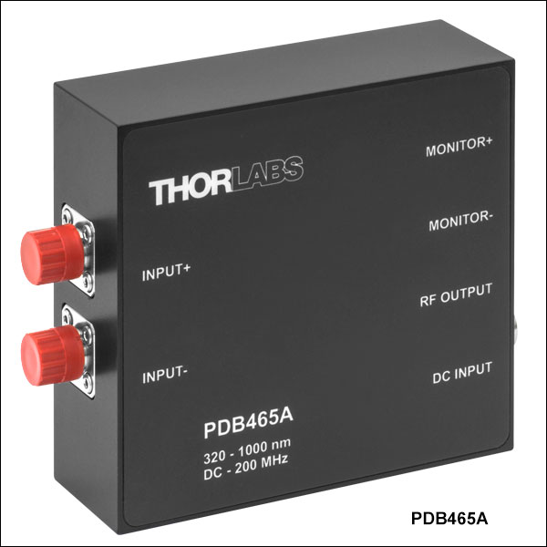
| Bandwidth (3 dB) | DC - 200 MHz AC Coupled (-AC Suffix): 100 Hz - 200 MHz |
|
| Common Mode Rejection Ratio |
>25 dB | |
| Transimpedance Gainb | 30 x 103 V/A | |
| Optical Inputs | FC/PC or FC/APC Compatible (Removable Adapter) |
FC/PC or FC/APC Compatible (Adapter is not Removable) |
| Monitor Output Bandwidth | DC - 1 MHz | |


 Zoom
Zoom| Specificationsa | ||
|---|---|---|
| Item # | PDB435A(-AC) | PDB435C(-AC) |
| Detector Type | Si/PIN | InGaAs/PIN |
| Wavelength Range | 320 - 1000 nm | 800 - 1700 nm |
| Max Responsivity (Typ.) | 0.50 A/W | 1.0 A/W |
| Active Detector Diameter | 0.4 mm | 0.15 mm |
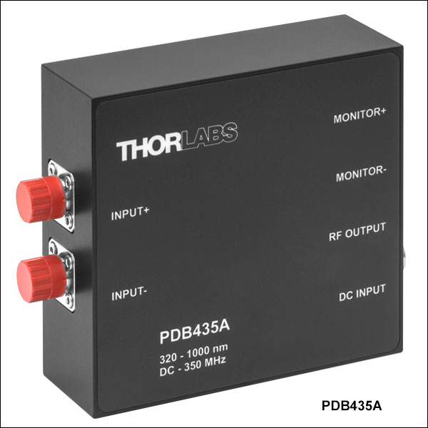
| Bandwidth (3 dB) | DC - 350 MHz AC Coupled (-AC Suffix): 100 Hz - 350 MHz |
|
| Common Mode Rejection Ratio |
>20 dB | |
| Transimpedance Gainb | 10 x 103 V/A | |
| Optical Inputs | FC/PC or FC/APC Compatible (Removable Adapter) |
FC/PC or FC/APC Compatible (Adapter is not Removable) |
| Monitor Output Bandwidth | DC - 1 MHz | |


 Zoom
Zoom| Specificationsa | ||
|---|---|---|
| Item # | PDB471C(-AC) | PDB470C(-AC) |
| Operating Wavelength | Optimized for 1060 nm (900 - 1400 nm Range) |
Optimized for 1300 nm (1200 - 1700 nm Range) |
| Detector Type | InGaAs/PIN | |
| Internal Coupling Fiber | HI1060 | SMF-28e+ |
| Responsivity (Typical) | 0.72 A/W @ 1060 nm | 0.85 A/W @ 1300 nm |
| Active Detector Diameter | 0.080 mm | 0.075 mm |
| Bandwidth (3 dB) | DC - 400 MHz AC Coupled (-AC Suffix): 100 Hz - 400 MHz |
|
| Common Mode Rejection Ratio | >25 dB (Typ. >30 dB) |
|
| Transimpedance Gainb | 10 x 103 V/A | |
| Optical Inputs | FC/APC | |
| Monitor Output Bandwidth | DC - 3 MHz | |

Click to Enlarge
The two vertical lines mark 1060 nm (red) and 1300 nm (blue). The shaded regions indicate the specified wavelength range for each detector.

 Zoom
Zoom| Specificationsa | ||
|---|---|---|
| Item # | PDB481C-AC | PDB480C-AC |
| Operating Wavelength | Optimized for 1060 nm (900 - 1400 nm Range) |
Optimized for 1300 nm (1200 - 1700 nm Range) |
| Detector Type | InGaAs/PIN | |
| Internal Coupling Fiber | HI1060 | SMF-28e+ |
| Responsivity (Typical) | 0.72 A/W @ 1060 nm | 0.85 A/W @ 1300 nm |
| Active Detector Diameter | 0.080 mm | 0.075 mm |
| Bandwidth (3 dB) | 30 kHz - 1.0 GHz | 30 kHz - 1.6 GHz |
| Common Mode Rejection Ratio |
>25 dB (Typ. >30 dB) |
|
| Transimpedance Gainb | 16 x 103 V/A | |
| Optical Inputs | FC/APC | |
| Monitor Output Bandwidth | DC - 3 MHz | |

Click to Enlarge
The two vertical lines mark 1060 nm (red) and 1300 nm (blue). The shaded regions indicate the operating wavelength range for each detector.

 Zoom
Zoom| Specificationsa | |
|---|---|
| Item # | PDB482C-AC |
| Operating Wavelength | Optimized for 1060 nm (900 - 1400 nm Range) |
| Detector Type | InGaAs/PIN |
| Internal Coupling Fiber | HI1060 |
| Responsivity (Typical) | 0.72 A/W @ 1060 nm |
| Active Detector Diameter | 0.080 mm |
| Bandwidth (3 dB) | 1 MHz - 2.5 GHz |
| Common Mode Rejection Ratio | >20 dB (>25 dB Typ.) |
| Transimpedance Gainb | 28 x 103 V/A |
| Optical Inputs | FC/APC |
| Monitor Output Bandwidth | DC - 2.5 MHz |

Click to Enlarge
The vertical line marks the detector's optimized wavelength (1060 nm) while the shaded region indicates the operating wavelength range.

 Zoom
Zoom
- Replacement Power Supply for the Balanced Amplified Photodetectors Sold Above
- ±12 VDC Power Output
- Current Limit Enabling Short Circuit and Overload Protection
- On/Off Switch with LED Indicator
- Switchable AC Input Voltage (100, 120, or 230 VAC)
- 2 m (6.6 ft) Cable with LUMBERG RSMV3 Male Connector
- UL and CE Compliant
The LDS12B ±12 VDC Regulated Linear Power Supply is intended as a replacement for the supply included with our PDB line of balanced photodetectors sold on this page. The cord has three pins: one for ground, one for +12 V, and one for -12 V (see diagram above). This power supply ships with a location-specific power cord. This power supply can also be used with the PDA series of amplified photodetectors, PMM series of photomultiplier modules, APD series of avalanche photodetectors, and the FSAC autocorrelator for femtosecond lasers.