Compact 5 GHz Balanced Detectors

- Differential Photodiode Pair with DC-Coupled Output
- Low-Artifact Performance in a Compact Package
- Available with HI1060 or SMF-28 Ultra Input Fibers
- Volume Pricing Available for OEMs
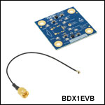
BDX1EVB
Evaluation Board for BDX1 Series Detectors
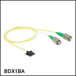
BDX1BA
Compact Balanced Detector with SMF-28 Fiber Leads (Patent Pending)
Zoomed-In View of a BDX1BA Detector
2.00"
(50.8 mm)
2.00"
(50.8 mm)

Please Wait
| Balanced Detector Selection Guide |
|---|
| Balanced Detectors with Fast Monitor Output |
| Large-Area Balanced Amplified Detectors |
| Suitable for OCT |
| Compact Balanced Amplified Detectors |
| Compact 5 GHz Balanced Detectors |
| OCT Balanced Detectors with Fast Monitor Output |
| Auto-Balanced Detector with Avalanche Photodiodes |
| Polarization-Dependent Balanced Detector |
Applications
- OEM Balanced Detection
- OCT Systems
- LIDAR Systems
- Optical Frequency Domain Reflectometry
- Compact Detection Systems

Janis Valdmanis, Ph.D. Optics
Ultrafast Optoelectronics
General Manager
We Design, Develop, and Manufacture
Equipment up to 70 GHz
Questions?
Demo Unit Requests?
Product Suggestions?
Custom or OEM Applications?
Features
- Balanced, 5 GHz, Differential Photodetector
- Wavelength Range: 950 nm to 1650 nm (Photodiode Material)
- BDX1CA: HI1060 Fiber, 980 - 1650 nm
- BDX1CA: SMF-28 Ultra Fiber, 1260 - 1625 nm
- Designed for Low-Artifact Applications
- Impulse Response: 70 ps (FWHM)
- Compact Package: 10.0 mm x 12.0 mm x 3.3 mm
- Surface Mount Component (Solders Directly to PCB)
- FC/APC-Terminated Versions Available from Stock; Contact
Tech Support for FC/PC or Bare Fiber Versions
The BDX1 series of high-speed, compact, fiber optic balanced detectors (patent pending) are designed for demanding OEM applications that require low-artifact performance. The surface mount package contains fiber and photodiode arrays configured on a common substrate for excellent response matching and precise timing for differential signal detection. This design achieves a high common mode rejection ratio (CMRR) and minimizes optical artifacts, which is especially important for highly sensitive techniques such as OCT and LIDAR.
The optoelectrical configuration of these detectors is simple and compact in order to support high volume applications where space and cost are a primary concern. Additionally, the compact mounting geometry allows for easy integration with conventional circuit boards and enables high-speed connection to subsequent amplifiers or other components. These BDX1 series detectors do not have built-in amplifiers.
The optical output from a pair of fibers is directed to two matched photodiodes in an array that are biased with positive (+5 V) and negative (-5 V) voltages and wired as a differential pair with a single, common output. This internal optical geometry is designed to eliminate unwanted reflections from traveling either forward or backward along the intended optical path. As a result, optical artifacts (spurious signals) in the detected and reflected signals are very low.
These compact balanced detectors provide a frequency response bandwidth of DC to 5 GHz and are available with two single mode input fiber options. The BDX1CA detector has HI1060 fiber leads with Ø900 µm loose-buffer jackets for applications in the 980 - 1650 nm wavelength range, while the BDX1BA detector has SMF-28 Ultra fiber leads with Ø900 µm loose-buffer jackets for single mode applications in the 1260 - 1625 nm wavelength range. The two fibers in each model are matched in length to 1 mm and are available from stock with narrow key FC/APC connectors. Units with FC/PC connectors or no connector are also available on request by contacting Tech Support.
We also offer the BDX1EVB Evaluation Board for testing the BDX1 series balanced detectors in a lab environment with common cable connections. This board features a pre-defined footprint for soldering a BDX1 series detector in place, and has specified points for connecting power and current monitor leads. Included with each BDX1EVB evaluation board is a micro-coaxial cable that transmits the high-speed output signal through an SMA connector.

Click to Enlarge
External Pin Connections for BDX1 Series Detectors.

Click to Enlarge
Internal Electrical Configuration for BDX1 Series Detectors.
Operation of BDX1 Series Balanced Detectors
Thorlabs' BDX1 Series Balanced Detectors provide differential detection of complementary signals. Each device consists of a fiber array that directs the two optical input signals to an array of well-matched photodiodes (see diagram to the near right). The output is the difference of the two input signals, which results in greatly reduced common mode noise.
The diagram to the far right indicates the external pin connections for each half-via contact of a BDX1 Series Balanced Detector. Soldering of the half-vias must be done cleanly and quickly. To avoid damaging the internal opto-electronic components, do not exceed 5 seconds of soldering time at 250 °C for each contact. When mounting to the BDX1EVB Evaluation Board or other PCB, ensure that all seven half-via contacts near the output are soldered and at least one of the ground contacts in each of the rear corners are soldered for a total of 9 contact points. All soldering must be done by hand; a reflow oven will damage the device. Please refer to the BDX1EVB Evaluation Board spec sheet for complete mounting instructions.
The components inside this module are ESD sensitive. Take all appropriate precautions to discharge personnel and equipment before making any electrical connections to the unit. This also applies to coaxial cables that easily accumulate capacitive change.

Click to Enlarge
The dimensions in this bottom view of the BDX1BA Balanced Detector are representative of all BDX1 Series Detectors.

Click to Enlarge
The dimensions in this top view of the BDX1BA Balanced Detector are representative of all BDX1 Series Detectors.
| Posted Comments: | |
| No Comments Posted |


Click to Enlarge
BDX1BA Balanced Detector Soldered to a BDX1EVB Evaluation Board with Connections for Output and Power
- Printed Circuit Board (PCB) for Mounting BDX1 Series Detectors
- Test Points for Monitoring Photodiode Current
- Includes a UMCC-to-SMA Coaxial Output Cable
The BDX1EVB Evaluation Board allows the user to solder a BDX1 series detector in place so that power and output connections can be made with common cables and connectors. The half-via contacts around the perimeter of the BDX1 detector can be soldered to the pre-defined contact points on the evaluation board. Included with each BDX1EVB Evaluation Board is a micro-coaxial cable that transmits the high-speed output signal through an SMA connector.
Our BDX1EVB Evaluation board features labeled connection points for making ground and power connections. Four additional test points can be used to monitor the photocurrent for each photodiode. To monitor the positive input photodiode (PD+), a high impedance voltmeter can be connected across the current sensing resistor R2 using test points TP1 and TP2. Similarly for the negative input photodiode (PD-), a high impedance voltmeter can be connected across the current sensing resistor R3 using test points TP3 and TP4. The voltmeter will read 10 mV for every 1 mA of photocurrent. Standard test leads with spring hooks (not included) should be used to make power, ground, and test point connections. Please refer to the BDX1EVB spec sheet for complete instructions on connecting and operating a BDX1EVB Evaluation Board.
The components inside this module are ESD sensitive. Take all appropriate precautions to discharge personnel and equipment before making any electrical connections to the unit. This also applies to coaxial cables that easily accumulate capacitive change. All soldering must be done by hand; a reflow oven will damage the device. Please refer to the BDX1EVB Evaluation Board spec sheet for complete mounting instructions.
 Products Home


 Zoom
Zoom
 Compact Balanced Detectors,5 GHz, OEM Package