 Products Home
Extinction Ratio Meter
- For Fast Alignment of Polarization-Maintaining Fibers
- Wavelength Range: 800 - 1700 nm
- Accuracy: 0.5 dB (ER) & 0.5° (Angle)
ERM100


Please Wait
ERM100 Applications
- Extinction Ratio (ER) Measurements of Polarization Maintaining (PM) Fibers
- Alignment of PM Fiber to Connector Key
- Alignment of PM Fiber to Laser Source
The ERM100 is an extinction ratio meter based on the rotating polarizer technique. This benchtop device offers a fast and simple way to measure the ER of Polarization Maintaining (PM) fibers. It is an easy-to-use device that may be utilized in many applications where the alignment of PM fibers is required.
How It Works
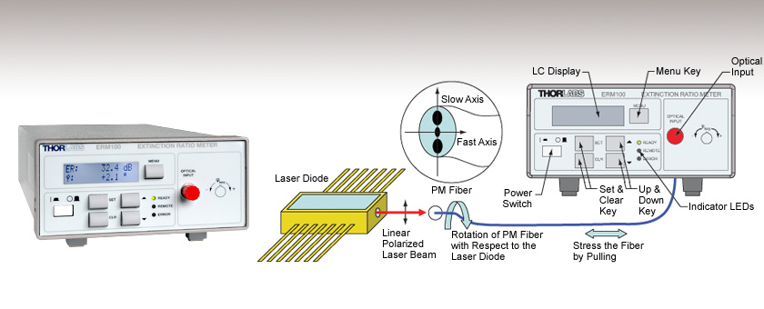
The ERM100 Extinction Ratio Meter contains a rotating polarizer followed by a detector, which generates a photocurrent. In general, this photocurrent will be a sinusoidal function in time with a DC offset. By simultaneously analyzing the DC offset and the depth of modulation, the meter is able to determine the degree to which the light field is linearly polarized, thereby yielding the extinction ratio.
Benefits
This benchtop instrument is an easy to use measurement device for any kind of PM fiber alignment application. A set of buttons and the LCD on the front panel allow quick adjustments and measurement procedure. Any PM alignment task can be performed efficiently.
The ERM100 is factory calibrated and can measure the ER, the misalignment angle, and the power. It can also be computer controlled via a USB connection. Drivers for LabVIEW™, LabWindows™/CVI™, MSVC, and Borland C are included.
The ERM100 is equipped with a FC/PC connector. For other connector types please contact our TechSupport.
Shipping Info
Each unit comes with the meter, a USB cable, software CD with LabVIEW™ and LabWINDOWS™CVI Driver Set, and a manual.
Application: PM Alignment
The ERM100 Extinction Ratio Meter can be used to align the axis of a PM fibers. The incident light of a PM fiber has to be linear polarized and must be coupled parallel to one of the main axes of the fiber to maintain the linear polarization. The ERM100 provides a convenient way to achieve this. There are two different common setups for such fiber alignments depending on the light source.
Broadband Sources (SLED)
Due to the wavelength dependent birefringence of these sources, only the coupling angle has to be changed until the optimal angle with the maximum ER value is found.
Narrow Band Sources (Laser Diodes)
There is neglectible wavelength depending birefringence for narrow band sources. To get a reliable value for the ER of the PM fiber all phaseshifts between fast and slow axes of the polarization states must be analysed. This can be achieved by stressing the fiber (stress induced birefringence) during the measurement while adjusting the coupling angle. For the optimal angle the maximum ER value should be stable and not depend on the stress on the fiber.
Typical Applications
- Optimized Coupling of Linear Polarized Light into PM Fibers
- Optimized Alignment to Connector Key
- Pigtailing (Alignment of Laser Diodes to PM Fibers)
ER Measurement on Narrow Band Sources

| ERM100 Specificationsa | |
|---|---|
| Wavelength Range | 800 - 1700 nm |
| Max. ERb | >40 dB |
| ER Accuracyb | 0.5 dB |
| ER Resolution | 0.1 dB |
| Angle Accuracyb | 0.5° |
| Angle Resolution | 0.1° |
| Dynamic Rangec | -40 to 10 dBm |
| Operating Temperature | 5 to 40 °C |
| Line Voltage | 100 V, 115 V, 230 V +15%/-10% |
Software for the ERM100 Series Extinction Ratio Meters:
The available software is organized into the following categories:
- Applications: Standard application-software packages and graphical user interfaces .
- Drivers: Instrument drivers for the National Instruments™, LabWindows™/CVI and LabVIEW™ development environments.
- Firmware: Low level software for the internal operation of the device.
- Utilities: Software tools for general use.
| Posted Comments: | |
Andrew Robertson
(posted 2020-07-08 10:34:51.043) I've got an ERM100 with an FC/PC connector, if I connect with a patch cord with FC/APC - will the measurement PER reading make any sense or is it completely unusable? Will it effect the angle measurement? dpossin
(posted 2020-07-08 11:13:45.0) Dear Andrew, Thank you for your feedback. Basically the ERM100 is just a rotating polarizer and a photodiode behind. Because the efficiency of the polarizer is angle dependent, the PER will be slightly under or overestimated by using an FC/APC connector together with ERM100 with FC/PC connection. Robbie Murray
(posted 2020-07-01 10:40:41.2) Hi. The ERM100 is a great product, and now an invaluable tool in our lab. I have a couple of questions though: 1) Is it OK to use FC/APC connectors, even though we have the FC/PC option?
2) I have been trying to measure the PER of the output of a fibre amplifier (keeping the power below 10 dB at all times). Above a certain input power level (approx -6 dBm), the PER monitor stops providing a PER reading and gives the input power to low. However, there is definitely enough power entering the PER meter. What state of input polarisation (i.e. unpolarized, certain level of DOP etc) would give this input error, even though there is power entering the device. I suspect that the increasing power from the fibre amplifier is causing depolarization of the signal, how would this affect the PER meter. Many thanks dpossin
(posted 2020-07-06 04:22:28.0) Dear Robert,
Thank you for your feedback and for sharing your positive impressions about the ERM100. We really appreciate that. Basically the ERM100 is just a rotating polarizer and a photodiode behind. Because the efficiency of the polarizer is angle dependent, the PER will be slightly under or overestimated by using an FC/APC connector together with ERM100 with FC/PC connection. I am reaching out to you in order to discuss your second question. Marcus Duelk
(posted 2020-02-13 14:04:49.237) Hello,
We have been using several of the ERM100 units over the past years. They have been working great for us. But, we would like to have something similar also for the visible range, like 400-800nm. Could you offer a variant of the ERM100 that is tailored to the visible range ? I am sure it will be mainly a matter of using a different polarization filter and a different photodetector inside, the architecture itself and the firmware could probably remain the same ...
Thanking in advance.
Best regards,
Marcus Duelk MKiess
(posted 2020-03-05 06:14:40.0) This is a response from Michael at Thorlabs. Thank you for the inquiry. We have the possibility to build some special designs here. However, due to the required optics it could become more difficult to cover the complete desired wavelength range without restrictions.
Depending on your application, our PAX1000VIS Polarimeter, would also be a good alternative.
I have contacted you directly to discuss the details with you. srikanth
(posted 2017-10-22 23:37:58.18) May I know dynamic range of ERM-100 in the wavelength range of 1000-1100nm?
Will ERM-100 works with line supply in India (~230V, 50Hz).
-srikanth swick
(posted 2017-11-06 03:32:56.0) This is a response from Sebastian at Thorlabs. Thank you for the inquiry.
The dynamic range at 1000-1100nm will be slightly shifted but still at approx. -40 dBm to 10 dBm. The ERM100 will work with line voltage 230V (50Hz). We have contacted you directly for further assistance. pskochinski
(posted 2017-09-11 09:11:11.84) What is the minimum input optical power required to achieve a PER measurement of 30dB or 40dB? swick
(posted 2017-09-14 04:41:24.0) This is a response from Sebastian at Thorlabs. Thank you for the inquiry.
For measuring PER of 40dB the optical input power should be > -30dBm. For PER of 30dB the power should be approx. > -33dBm to -35dBm
The exact power level limitation is dependent on noise and wavelength. I will contact you directly to provide further assistance. user
(posted 2016-01-14 17:29:28.627) How do you change the time stamp on ERM-100 software app to match with the time on the connected PC? Thank you. shallwig
(posted 2016-01-15 10:52:15.0) This is a response from Stefan at Thorlabs. Thank you very much for your inquiry. In the software GUI of the ERM100 it is not possible to modify the time stamp. The software package also contains drivers for programming in Labview. Here it should be possible to implement the time from the connected PC into your measurement. As you left no contact data please contact me at euorpe@thorlabs.com for further question. ddewitte
(posted 2014-09-19 11:41:18.887) What fiber connectors are available for this unit? Also would it be possible to make the connectors swappable? Do you have an ER meter for visible wavelengths (400 - 800nm)?
Thank you,
~Daniel DeWitte shallwig
(posted 2014-09-22 04:09:47.0) This is a response from Stefan at Thorlabs. Thank you very much for your inquiry. We can offer this extinction ratio meter with FC/PC and FC/APC connectors, the connectors are not swappable. At the moment we have the ERM100 with a specified wavelength range from 800 -1700nm and we can offer a special version for the wavelengths range 600-1000nm. We are still working on an ER meter for the visible range. I will contact you directly to discuss your application in detail. tcohen
(posted 2012-02-21 11:24:00.0) Response from Tim at Thorlabs: Thank you for your feedback. We are able to offer a custom ERM100 with higher attenuation in the collimator such that you can use it at +20dBm. We have contacted you directly with more information. stephen_yeh
(posted 2012-02-20 10:16:28.0) Hello,
ERM100's spec says max. power range is +10dBm. Can it make +20dBm at 1550nm? or have to use attenuator together?
thanks apalmentieri
(posted 2010-01-21 08:44:59.0) A response from Adam at Thorlabs to Aditya: The warranty on the ERM100 is 2 years. aditya.suresh
(posted 2010-01-20 20:30:59.0) Can you please let me know if there is a manufaturers warranty etc for this product? Laurie
(posted 2009-02-24 08:24:17.0) Response from Laurie at Thorlabs to anton: Thank you for your interest in our products and your feedback. Currently, Thorlabs does not offer any splicing equipment. However, if desired, our ERM100 can be used to monitor the polarization after splicing is completed. Many third party splicers have built-in monitoring systems that keep track of the light intensity profiles of the light from each fiber splice. Someone from our technical support staff will be contacting you directly to provide a bit more information on these third-party splicers. anton
(posted 2009-02-10 09:03:32.0) I need to splice two PM fibers with polarization extinction ratio above 37 dB. Can I use this device for this purpose? If yes, could you please advise the scheme because I did not find that in the user manual. |