 Products Home
APT NanoTrak® Auto-Alignment Module

- Advanced Closed-Loop First Light Detection
- IR (InGaAs) Detector and PIN Current Inputs Supplied
- Visible (Si) Detector Also Available
- 2 High Voltage Piezo Actuator Output Channels
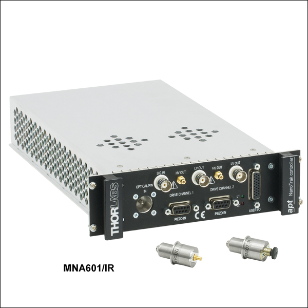
MNA601/IR
MMR601
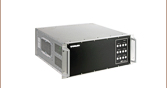
Rack with Modules
Full Suite of Software
Support Tools Included


Please Wait
| APT™ Rack System Modules |
|---|
| 2-Channel Piezo Control Module |
| 2-Channel Stepper Motor Control Module |
| 2-Channel NanoTrak® Auto-Alignment Module |
| USB Motion Control 19" Rack Chassis |
| All Thorlabs' Rack System Modules require the use of the APT™ MMR601 Rack System Enclosure. Independent operation of the modules outside the enclosure is not possible. |
Features
- Tracking Feature Maintains Optimum Throughput Indefinitely
- Advanced Dark Search Algorithms for First Light Detection with Motorized Fiber Launch
- Active Fiber Alignment for maintaining alignment during processes and experimentation
- IR (InGaAs) & PIN Current Inputs Supplied
- Visible (Si) Detectors Available Separately
- Mainframe Access Mix and Match up to 6 Modules, Stepper, Piezo, and NanoTrak® Each with Two Channels
- USB Plug and Play Connectivity
- Full Software GUI Control Suite
- ActiveX® Graphical Panel Controls & Programming Interfaces
- Seamless Software Integration with Entire APT Family of Products (Electronics and Mechanics)
The modular NanoTrak Auto-Alignment Controller combines an intelligent, active-feedback, alignment control system and a two-channel, piezoelectric controller into a single plug-in unit. As part of the APT™ series, this autoalignment system represents the latest developments in automated optical alignment technologies. This system is a basic building block from which advanced alignment systems can be quickly configured. It can be fully integrated into a rack system that is comprised of a selection of our plug-ins: piezoelectric controllers, stepper motor controllers, and this NanoTrak autoalignment module. The Controller is available with InGaAs (900 - 1700 nm) or Si (320 - 1000 nm) detectors.
The initial coupling of light from one device (e.g. fiber) to another involves searching a multidimensional space until a signal is detected. The NanoTrak support software offers a series of motor search algorithms for this first light detection. Although used primarily for aligning optical fibers and integrated optical devices, the NanoTrak is ideal for automating just about any labor intensive alignment tasks such as waveguide characterization, fiber pigtailing of active and passive devices, as well as a multitude of other R&D applications.
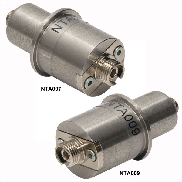
The NanoTrak is supplied with an Infrared wavelength (InGaAs) detector (NTA007) and a PIN diode SMB input for use with external detector heads. A visible wavelength (Si) detector (NTA009) is available separately as detailed below.
| NanoTrak® Automated Fiber Alignment Controllers | ||
|---|---|---|
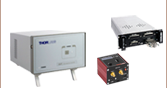
| K-Cube™ 2-Channel Controllers | Benchtop 2-Channel Controller | Modular 2-Channel Rack System Module |
Module Specifications
| Signal Measurement | |
|---|---|
| PIN Photodiode | |
| Mechanical Connector | SMB Male |
| Photocurrent Range | 1 nA to 10 mA |
| Optical Connector | FC/PC |
| NanoTraking | |
| Circle Scanning Frequency | 1 to 300 Hz |
| Circle Position Range | <1% to >99% MPE |
| Circle Diameter Adj. Modes | Automatic and Manual |
| Signal Phase Compensation | ±180° |
| Piezoelectric Input/Output | |
| Number of Piezo Channels | 2 |
| HV Output Connectors | |
| Connector Type | SMC Male |
| Voltage Output | 0 to 75 VDC/Channel |
| Voltage Stability | 100 ppm over 24 Hours |
| Noise | <3 mV (RMS) |
| Output Current | 500 mA/Channel |
| Analog Output Monitors | |
| Connector Type | BNC |
| Voltage Range | 0 to 10 VDC |
| Strain Gauge Position Feedback | |
| Connector Type | 9-Pin D-Type Female |
| Feedback Type | AC |
| Other Input/Output | |
| Optical Power Monitor | |
| Connector Type | BNC |
| Voltage Range | 0 to 10 VDC |
| Ext Signal In Input | |
| Connector Type | BNC |
| Voltage Range | 0 to 10 VDC |
| User Control | |
| Connector Type | 26-Pin HD D-Type Female |
| Isolated Digital Inputs | 4 off TTL |
| Isolated Digital Outputs | 4 off TTL |
| Trigger Input | 1 off TTL |
| Trigger Output | 1 off TTL |
| Potentiometer Channel Ctrl Input | 1-10 k (Each Channel) |
| Analog Channel Output Monitors | 0 to 10 VDC (Each Channel) |
| General | |
| Dimensions (W x D x H) | 190 mm x 270 mm x 50 mm |
| Weight | 1.5 kg (3.3 lbs) |
Optical Detector Specfications
| Item # | NTA007 | NTA009 |
|---|---|---|
| Detector Type | InGaAs | Si |
| Operating Wavelength | 900 - 1700 nm | 320 - 1000 nm |
| Active Area | Fiber Input | Fiber Input |
| Rise Time | 100 ps @ 12 V | 100 ps @ 12 V |
| NEP | 4.5 x 10⁻¹⁵ W/√Hz | 1.5 x 10⁻¹⁵ W/√Hz |
| Dark Current | 0.05 nA @ 5 V | 0.01 nA @ 10 V |
NanoTrak® Controller
D-type Female

| Pin | Description | Return | Pin | Description | Return | Pin | Description | Return |
|---|---|---|---|---|---|---|---|---|
| 1 | DIG I/P 1a | 19 | 10 | DIG O/P 1a | 19 | 19 | Isolated Groundb | - |
| 2 | DIG I/P 2a | 19 | 11 | DIG O/P 2a | 19 | 20 | Ext Trigger I/P | 22 |
| 3 | DIG I/P 3a | 19 | 12 | DIG O/P 3a | 19 | 21 | Ext Trigger O/P | 22 |
| 4 | DIG I/P 4a | 19 | 13 | DIG O/P 4a | 19 | 22 | Ground | - |
| 5 | Channel 1 RS485 (+) | - | 14 | Channel 2 RS485 (+) | - | 23 | 5 V User O/P (Isolated) | - |
| 6 | Channel 1 RS485 (-) | - | 15 | Channel 2 RS485 (+) | - | 24 | Not Used | - |
| 7 | Not Used | - | 16 | Not Used | - | 25 | Analog Ground | - |
| 8 | Channel 2 10 V O/Pc | 25 | 17 | External Analog I/P CH2 0 - 10 V | 25 | 26 | Signal Power Outd | 25 |
| 9 | Channel 1 10 V O/Pc | 25 | 18 | External Analog I/P CH1 0 - 10 V | 25 |
Piezo Controller
D-type Female

| Pin | Description | Return | Pin | Description | Return | Pin | Description | Return |
|---|---|---|---|---|---|---|---|---|
| 1 | Wheatstone Bridge Excitation | 4 or 6 | 4 | D.C.(+) or Equipment Grounda | - | 7 | D.C.(-) or Actuator ID Signala,b | 4 or 6 |
| 2 | +15Vc | 4 or 6 | 5 | Feedback Signal In | 4 or 6 | 8 | RS485 (-) | 9 |
| 3 | -15Vc | 4 or 6 | 6 | Equiptment Ground | - | 9 | RS485 (+) | 8 |
LV Out
BNC Female

0 to +10V. This output is mirrors HV OUT, 10V being equivalent to 75V on the HV outputs, and can be connected to an oscilloscope to enable the drive signal of the piezo actuator to be monitored.
HV Out
SMC

0 to 75V, 0 to 500mA. Provides the drive signal to the piezo actuator.
Signal In
BNC Female
0 to 10V, 100kΩ load. Used to receive a signal of optical power from an external power meter.
Principle of Operation
During the auto-alignment process, the NanoTrak® uses gradient search algorithms to locate the direction of a peak signal. This operation is similar to that of a compass finding the north pole. The sensitivity of the search is such that even far away from the peak signal, where there are small power gradients, the NanoTrak can decide in which direction the peak signal is located. This information is then used to make positional corrections via the attached high speed piezo actuators without having to map or search a large area.
In the proximity of a peak signal, the signal gradient seen is much smaller, indicating that smaller positional correction is required. When peak signal is reached the gradient seen changes to zero, indicating that no positional correction is needed.
The dynamic behavior of the NanoTrak allows it to continue the alignment process indefinitely. Should the alignment change, the gradient search will detect the change and make a corrective move.
Typical Application Example (Optical Device Alignment)
Optical power transmission through any system under alignment can be described as a Gaussian coupling. Coupled power lowers as a function of distance relative to the aligned position (dependent upon device). Discrete power level alignments can be thought of as positions about the ideal coupling position, where the distances from the aligned position are equal. These discrete power alignment positions form concentric circles. These concentric circles represent the power contours and can be thought of as the gradient contours of a hill on a topographic map.
By detecting the gradient of the power at any given position, the NanoTrak can adjust the position until the power is maximized and the gradient becomes zero. This is achieved by scanning over the contours in a circular path to establish the direction of the signal maximum on the circular trajectory. The origin of the scan circle is then moved in the direction of the signal maximum.
Continuous active alignment can be used to maintain alignment, or the search algorithms can be halted for next step assembly or R&D operations.
Thorlabs offers two platforms to drive our wide range of motion controllers: our Kinesis® software package or the legacy APT™ (Advanced Positioning Technology) software package. Either package can be used to control devices in the Kinesis family, which covers a wide range of motion controllers ranging from small, low-powered, single-channel drivers (such as the K-Cubes™ and T-Cubes™) to high-power, multi-channel, modular 19" rack nanopositioning systems (the APT Rack System).
The Kinesis Software features .NET controls which can be used by 3rd party developers working in the latest C#, Visual Basic, LabVIEW™, or any .NET compatible languages to create custom applications. Low-level DLL libraries are included for applications not expected to use the .NET framework. A Central Sequence Manager supports integration and synchronization of all Thorlabs motion control hardware.

Kinesis GUI Screen

APT GUI Screen
Our legacy APT System Software platform offers ActiveX-based controls which can be used by 3rd party developers working on C#, Visual Basic, LabVIEW™, or any Active-X compatible languages to create custom applications and includes a simulator mode to assist in developing custom applications without requiring hardware.
By providing these common software platforms, Thorlabs has ensured that users can easily mix and match any of the Kinesis and APT controllers in a single application, while only having to learn a single set of software tools. In this way, it is perfectly feasible to combine any of the controllers from single-axis to multi-axis systems and control all from a single, PC-based unified software interface.
The software packages allow two methods of usage: graphical user interface (GUI) utilities for direct interaction with and control of the controllers 'out of the box', and a set of programming interfaces that allow custom-integrated positioning and alignment solutions to be easily programmed in the development language of choice.
A range of video tutorials is available to help explain our APT system software. These tutorials provide an overview of the software and the APT Config utility. Additionally, a tutorial video is available to explain how to select simulator mode within the software, which allows the user to experiment with the software without a controller connected. Please select the APT Tutorials tab above to view these videos.
Software
Kinesis Version 1.14.25
The Kinesis Software Package, which includes a GUI for control of Thorlabs' Kinesis and APT™ system controllers.
Also Available:
- Communications Protocol
Software
APT Version 3.21.4
The APT Software Package, which includes a GUI for control of Thorlabs' APT™ and Kinesis system controllers.
Also Available:
- Communications Protocol
These videos illustrate some of the basics of using the APT System Software from both a non-programming and a programming point of view. There are videos that illustrate usage of the supplied APT utilities that allow immediate control of the APT controllers out of the box. There are also a number of videos that explain the basics of programming custom software applications using Visual Basic, LabView and Visual C++. Watch the videos now to see what we mean.
 |
Click here to view the video tutorial | |
To further assist programmers, a guide to programming the APT software in LabView is also available.
 |
Click here to view the LabView guide | |
| Posted Comments: | |
Rich Rademacher
(posted 2019-10-09 11:46:45.533) Hello,
I am working on a nanopositioning project using the MMR601 product. This project requires custom automation and so we cannot use the APT or Kinesis GUI. I do see you have the APT protocol documented and I think we can use this. However, USB is a problem for us.
I see the MMR601 has an external RS485 port on the D-sub user connector. Does this port use the same APT protocol, but obviously without the FTDI chip USB wrapper?
Thanks,
Rich cwright
(posted 2019-10-11 06:19:55.0) Hello Rich,
thank you for contacting us. Yes, the serial commands described in the communication protocol can be used to communicate with the controller over the RS484 pins. The communications protocol is identical regardless of the interface used - USB or RS485. TechnicalMarketing
(posted 2007-10-19 14:58:03.0) Thank you for taking the time to point out the typo in our price box. We appreatiate your contribution to our effort of improving the accuracy and content of Thorlabs website. cjohns
(posted 2007-10-19 14:20:35.0) MNA601/IR - Should be "InGaAs" detector? |

 Zoom
ZoomWhen used with the MMR601 or MMR602 rack systems, the NanoTrak® controller optimizes the coupling power when aligning optical devices. The output piezo drive signal is used to position the input and output devices for optimum throughput. It is shipped with an IR range (InGaAs) detector and a PIN current adapter. A visible range (Si) detector (NTA009) is available separately (see below).

 Zoom
ZoomThese infrared (NTA007) and visible (NTA009) wavelength detector heads are compatible with the benchtop (BNT001/IR), previous-generation T-Cube™ (TNA001/IR), and rack-mounted (MNA601/IR) NanoTrak® controllers.
| Item # | Wavelength Range | Active Area | Fiber Input | Dark Current | Junction Capacitance |
|---|---|---|---|---|---|
| NTA009 | 320 - 1000 nm | Ø 0.8 mm | FC/PC | 0.01 nA (Typ.) @ 10 V | 3.00 pF(Typ.) @ 10 V |
| NTA007 | 900 - 1700 nm | Ø 0.12 mm | FC/PC | 0.05 nA (Typ.) @ 5 V | 2.0 pF (Typ.) @ 5 V |
