 Products Home
USB Motion Control 19" Rack Chassis
- Up to 12 Drive Channels in a Single Chassis
- Motor, Piezo, and Auto-Alignment Driver Modules
- Ideal for Creating Multi-Axis Intergrated Positioning Systems
MMR601
Full Suite of Software Support Tools Included


Please Wait
| Rack System Motion Control Modules |
|---|
| 2-Channel Piezo Control Module |
| 2-Channel Stepper Motor Control Module |
| 2-Channel NanoTrak® Auto-Alignment Module |
| USB Motion Control 19" Rack Chassis |
Features
- Three Plug-in Modules
- Dual-Channel Piezoelectric Controller
- Dual-Channel Stepper Motor Controller
- NanoTrak® Auto-Alignment Controller
- Room for 6 Modules per 4U Chassis
- USB Plug-and-Play
- Multiple Racks Controlled by a Single Host PC
- Full Kinesis® Software Control Suite Included
- Intuitive Software Graphical Control Panels
- Extensive ActiveX® Programming Interfaces
- Fully Software Integrated with Other APT™ Family Controllers
(Integrated Systems Development)
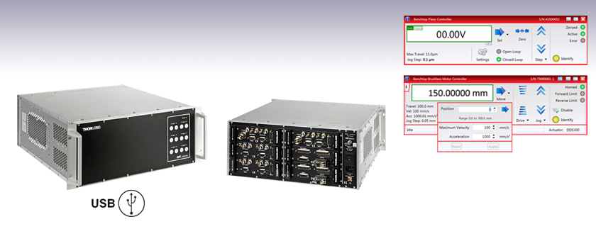
The MMR601(602) 19" Rack System is a multi-channel multi function modular architecture designed specifically for high axis count motion control applications. This new system is a sophisticated, self-contained, extendable-architecture, precision motion control platform. As a modular system it is possible to load it with the exact number and mix of required control modules covering motor drives (MST), piezo drives (MPZ) and the powerful Thorlabs NanoTrak® autoalignment technology (MNA). It deploys the same advanced high speed digital signal processing (DSP) technology and low noise analog circuitry pioneered in the equivalent APT™ benchtop controllers.
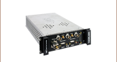
The modular rack is available with a cover (MMR602) for benchtop use, or without a cover (MMR601) for mounting in a standard 19" cabinet, and provides a highly functional 12 channel platform within the footprint of a 4U, 19" rack enclosure.
USB connectivity provides easy 'Plug-and-Play' PC-controlled operation with two available software platforms: our new Kinesis software or our legacy APT (Advanced Positioning Technology) software. The Kinesis Software features new .NET controls, which can be used by third-party developers working in the latest C, C#, Visual Basic, LabVIEW™, or any .NET-compatible languages to create custom applications. Our legacy APT software allows the user to quickly set up complex move sequences with advanced controls made possible via the ActiveX® programming environment. For example, all relevant operating parameters are set automatically by the software for Thorlabs' stage and actuator products. For more details on both software packages, please see the Motion Control Software, Kinesis Tutorials, and APT Tutorials tabs.
It is perfectly feasible to combine operation of this rack system with any of the benchtop controllers and control everything from the same unified Kinesis or APT software interface, allowing a common learning curve for both benchtop and rack based solutions.
| Specification | Value |
|---|---|
| Enclosure | Standard 19" Rack, 4U High |
| Module Bays | 6 Modular Slots, Back Panel Access |
| Communications | USB 1.1 Interface |
| Power Input | |
| Voltage | 85-264 VAC |
| Frequency | 47-63 Hz |
| Power | 800 W |
| Fuse | 15 A |
| Dimensions (W x D x H): | 480 x 448 x 183 mm (19.0" X 17.6" X 7.0") |
| Weight | 16 kg (35.2 lbs) |
Piezo Driver Bandwidth Tutorial
Knowing the rate at which a piezo is capable of changing lengths is essential in many high-speed applications. The bandwidth of a piezo controller and stack can be estimated if the following is known:
- The maximum amount of current the controllers can produce. This is 0.5 A for our BPC Series Piezo Controllers, which is the driver used in the examples below.
- The load capacitance of the piezo. The higher the capacitance, the slower the system.
- The desired signal amplitude (V), which determines the length that the piezo extends.
- The absolute maximum bandwidth of the driver, which is independent of the load being driven.
To drive the output capacitor, current is needed to charge it and to discharge it. The change in charge, dV/dt, is called the slew rate. The larger the capacitance, the more current needed:

For example, if a 100 µm stack with a capacitance of 20 µF is being driven by a BPC Series piezo controller with a maximum current of 0.5 A, the slew rate is given by

Hence, for an instantaneous voltage change from 0 V to 75 V, it would take 3 ms for the output voltage to reach 75 V.
Note: For these calculations, it is assumed that the absolute maximum bandwidth of the driver is much higher than the bandwidths calculated, and thus, driver bandwidth is not a limiting factor. Also please note that these calculations only apply for open-loop systems. In closed-loop mode, the slow response of the feedback loop puts another limit on the bandwidth.
Sinusoidal Signal

The bandwidth of the system usually refers to the system's response to a sinusoidal signal of a given amplitude. For a piezo element driven by a sinusoidal signal of peak amplitude A, peak-to-peak voltage Vpp, and frequency f, we have:

A diagram of voltage as a function of time is shown to the right. The maximum slew rate, or voltage change, is reached at t = 2nπ, (n=0, 1, 2,...) at point a in the diagram to the right:

From the first equation, above:

Thus,
For the example above, the maximum full-range (75 V) bandwidth would be
 .
.
For a smaller piezo stack with 10 times lower capacitance, the results would be 10 times better, or about 1060 Hz. Or, if the peak-to-peak signal is reduced to 7.5 V (10% max amplitude) with the 100 µm stack, again, the result would be 10 times better at about 1060 Hz.

Triangle Wave Signal
For a piezo actuator driven by a triangle wave of max voltage Vpeak and minimum voltage of 0, the slew rate is equal to the slope:
![]() .
.
Or, since f = 1/T:


Square Wave Signal
For a piezo actuator driven by a square wave of maximum voltage Vpeak and minimum voltage 0, the slew rate limits the minimum rise and fall times. In this case, the slew rate is equal to the slope while the signal is rising or falling. If tr is the minimum rise time, then

or
 .
.
For additional information about piezo theory and operation, see the Piezoelectric Tutorials page.
Thorlabs offers two platforms to drive our wide range of motion controllers: our Kinesis® software package or the legacy APT™ (Advanced Positioning Technology) software package. Either package can be used to control devices in the Kinesis family, which covers a wide range of motion controllers ranging from small, low-powered, single-channel drivers (such as the K-Cubes™ and T-Cubes™) to high-power, multi-channel, modular 19" rack nanopositioning systems (the APT Rack System).
The Kinesis Software features .NET controls which can be used by 3rd party developers working in the latest C#, Visual Basic, LabVIEW™, or any .NET compatible languages to create custom applications. Low-level DLL libraries are included for applications not expected to use the .NET framework. A Central Sequence Manager supports integration and synchronization of all Thorlabs motion control hardware.

Kinesis GUI Screen

APT GUI Screen
Our legacy APT System Software platform offers ActiveX-based controls which can be used by 3rd party developers working on C#, Visual Basic, LabVIEW™, or any Active-X compatible languages to create custom applications and includes a simulator mode to assist in developing custom applications without requiring hardware.
By providing these common software platforms, Thorlabs has ensured that users can easily mix and match any of the Kinesis and APT controllers in a single application, while only having to learn a single set of software tools. In this way, it is perfectly feasible to combine any of the controllers from single-axis to multi-axis systems and control all from a single, PC-based unified software interface.
The software packages allow two methods of usage: graphical user interface (GUI) utilities for direct interaction with and control of the controllers 'out of the box', and a set of programming interfaces that allow custom-integrated positioning and alignment solutions to be easily programmed in the development language of choice.
A range of video tutorials is available to help explain our APT system software. These tutorials provide an overview of the software and the APT Config utility. Additionally, a tutorial video is available to explain how to select simulator mode within the software, which allows the user to experiment with the software without a controller connected. Please select the APT Tutorials tab above to view these videos.
Software
Kinesis Version 1.14.25
The Kinesis Software Package, which includes a GUI for control of Thorlabs' Kinesis and APT™ system controllers.
Also Available:
- Communications Protocol
Software
APT Version 3.21.4
The APT Software Package, which includes a GUI for control of Thorlabs' APT™ and Kinesis system controllers.
Also Available:
- Communications Protocol
Thorlabs' Kinesis® software features new .NET controls which can be used by third-party developers working in the latest C#, Visual Basic, LabVIEW™, or any .NET compatible languages to create custom applications.
C#
This programming language is designed to allow multiple programming paradigms, or languages, to be used, thus allowing for complex problems to be solved in an easy or efficient manner. It encompasses typing, imperative, declarative, functional, generic, object-oriented, and component-oriented programming. By providing functionality with this common software platform, Thorlabs has ensured that users can easily mix and match any of the Kinesis controllers in a single application, while only having to learn a single set of software tools. In this way, it is perfectly feasible to combine any of the controllers from the low-powered, single-axis to the high-powered, multi-axis systems and control all from a single, PC-based unified software interface.
The Kinesis System Software allows two methods of usage: graphical user interface (GUI) utilities for direct interaction and control of the controllers 'out of the box', and a set of programming interfaces that allow custom-integrated positioning and alignment solutions to be easily programmed in the development language of choice.
For a collection of example projects that can be compiled and run to demonstrate the different ways in which developers can build on the Kinesis motion control libraries, click on the links below. Please note that a separate integrated development environment (IDE) (e.g., Microsoft Visual Studio) will be required to execute the Quick Start examples. The C# example projects can be executed using the included .NET controls in the Kinesis software package (see the Kinesis Software tab for details).
 |
Click Here for the Kinesis with C# Quick Start Guide Click Here for C# Example Projects Click Here for Quick Start Device Control Examples |
|
LabVIEW
LabVIEW can be used to communicate with any Kinesis- or APT-based controller via .NET controls. In LabVIEW, you build a user interface, known as a front panel, with a set of tools and objects and then add code using graphical representations of functions to control the front panel objects. The LabVIEW tutorial, provided below, provides some information on using the .NET controls to create control GUIs for Kinesis- and APT-driven devices within LabVIEW. It includes an overview with basic information about using controllers in LabVIEW and explains the setup procedure that needs to be completed before using a LabVIEW GUI to operate a device.
 |
Click Here to View the LabVIEW Guide Click Here to View the Kinesis with LabVIEW Overview Page |
|
These videos illustrate some of the basics of using the APT System Software from both a non-programming and a programming point of view. There are videos that illustrate usage of the supplied APT utilities that allow immediate control of the APT controllers out of the box. There are also a number of videos that explain the basics of programming custom software applications using Visual Basic, LabView and Visual C++. Watch the videos now to see what we mean.
 |
Click here to view the video tutorial | |
To further assist programmers, a guide to programming the APT software in LabView is also available.
|
Click here to view the LabView guide | |
| Posted Comments: | |
| No Comments Posted |