Fiber Optic Cannulae with Diffuser Tip, Ø200 µm Core

- Diffuser Tip Scatters Output Light Over Wide Angle
- 2, 5, 10, or 20 mm Fiber Length
- Ø1.25 mm Ceramic Ferrule
- Custom Versions Available
CFDSB02
2 mm Cannula Fiber with Diffuser Tip
CFDSB05
5 mm Cannula Fiber with Diffuser Tip
CFDSB10
10 mm Cannula Fiber with Diffuser Tip
CFDSB20
20 mm Cannula Fiber with Diffuser Tip
Cannula Without Diffuser Tip
Cannula With Diffuser Tip
Application Idea

Please Wait
| Fiber Optic Cannulae Selection Guide |
|---|
| Ø105 µm Core, 0.22 NA Fiber |
| Ø200 µm Core, 0.22 NA Fiber |
| Ø200 µm Core, 0.39 NA Fiber |
| Ø200 µm Core, 0.50 NA Fiber |
| Ø300 µm Core, 0.39 NA Fiber |
| Ø400 µm Core, 0.39 NA Fiber |
| Ø400 µm Core, 0.50 NA Fiber |
| Dual-Core Cannulae |
| Cannulae with Diffuser Tip |
| Cannula Fiber Specifications | |
|---|---|
| Fiber Type | FT200EMT |
| Wavelength Range (Click for Plot) |
400 - 2200 nm |
| Fiber Core Diameter | 200 ± 5 µm |
| Fiber Outer Diameter | 225 ± 5 μm |
| Numerical Aperture | 0.39 (Without Diffuser Tip) |
| Transmission (Typical)a | 95% @ 470 nm |
| Min/Max Output Powerb | ≥50% Over 220° Range @ 470 nm |

Click to Enlarge
Comparison of CFMLC12L10 Standard Cannula with CFDSB10 Cannula with Diffuser Tip; the output powers are not normalized relative to each other. For normal cannula, the profile is wavelength independent; however, with the diffuser tip, there is increased scattering for shorter wavelengths.

Click to Enlarge
The diffuser tip scatters the ouput light.
Features
- Cannulae with Diffuser Tip that Scatters Output Light (>220° Angle)
- Easier Excitation of Cells and Less Dependence on Fiber Orientation
- Ø200 µm Core, 0.39 NA Fiber Secured in Ø1.25 mm (LC) Ceramic Ferrule
- Custom Cannulae Available (Contact Tech Support with Inquiries)
Thorlabs' Diffusing Cannulae feature a tip made from a highly diffusing material that scatters the output light over a wide angle. The diffuser material provides a high scattering cross section over the entire operating wavelength range. This allows for simpler optical excitation of all cells near the implanted cannula and less dependence on the fiber orientation. Diffused cannulae can also be used in imaging applications.
These cannulae use a Ø200 µm, 0.39 NA fiber (Item # FT200EMT) secured within a Ø1.25 mm (LC) ceramic ferrule. The fiber ends are flat cleaved to a pre-determined length (2, 5, 10, or 20 mm). An implant guide for the cannulae sold on this page is also available below in packs of one or five; the 2 mm cannula cannot be used with an implant guide.
Ceramic LC ferrules are minimally invasive and lightweight, making them ideal for smaller specimens or placing multiple cannulae in close proximity. After implantation using stereotaxic guidance, the ferrule remains exposed; this provides an interface with our line of Optogenetics Equipment (see below for a diagram of a typical setup).
Each cannula includes a protective cap that shields the ferrule end from dust and other hazards. Additional CAPL Fiber Caps are also sold separately. If the ferrule end becomes dirty from use, we offer a selection of inspection tools, as well as fiber optic cleaning products.
Cleaning and Handling
The cannula fiber can be gently wiped with a Kimwipe®† or CTA10 Cotton-Tipped Applicator and 70% ethanol or isopropyl alcohol. The cannula can also be cleaned using an ultrasonic cleaner while ensuring that the tip does not come into contact with any solid surface.
†Kimwipes® is a registered trademark of the Kimberly-Clark Corporation.
Mating Sleeve and Patch Cable Compatibility
The ferrule diameter of a patch cable and cannula is the key factor for physical compatibility with an interconnect or mating sleeve. Mixing stainless steel and ceramic ferrules should not introduce significant additional signal losses. Cannulae and patch cables using Ø1.25 mm (LC) ferrules can be connected using the ADAL1 mating sleeve or ADAL3 interconnect.
Custom Cannulae and High-Volume Orders
Thorlabs also manufactures custom fiber optic cannulae. We can provide different scattering profiles, fiber and/or ferrule types, as well as different fiber lengths; please contact Tech Support for details. High-volume orders are also possible; please contact OEM Sales for more information.
Optogenetics Product Family for In Vivo Applications
Thorlabs offers a wide variety of products designed to support in vivo optogenetics applications. Please visit the OG Selection Guide tab above to see a full listing of available products for different applications.

| Related Optogenetics Products | ||||
|---|---|---|---|---|
| Light Sources | Patch Cables (Ø200 µm Core, 0.39 NA) | Mating | Cannulae (Ø200 µm Core, 0.39 NA) | Accessories |
| Fiber-Coupled LEDs MM Laser, 473 nm |
Standard Rotary Joint Dual Core Bifurcated Y-Cables |
Interconnects Mating Sleeves |
Standard Dual Core Diffuser Tip |
Implant Guides Cannula Holders |
| Quick Links | |||
|---|---|---|---|
| Single-Site Stimulation | |||
| One Light Source to One Cannula Implant | |||
| Bilateral Stimulation | |||
| One Light Source to Two Cannula Implants Using Rotary Joint Splitter | |||
| One or Two Light Sources to Two Cannula Implants | |||
| Two Light Sources into One Dual-Core Cannula Implant | |||
| Illumination | |||
| Fiber-Coupled LEDs and Drivers | |||
Optogenetics Selection Guide
Thorlabs offers a wide range of optogenetics components; the compatibility of these products in select standard configurations is discussed in detail here. Please contact Technical Support for assistance with items outside the scope of this guide, including custom fiber components for optogenetics.
Single-Site Stimulation
One Light Source to One Cannula Implant
The most straightforward method for in vivo light stimulation of a specimen is to use a single fiber optic with a single LED light source. The single wavelength LED is powered by an LED driver, and then the illumination output is fiber-coupled into a patch cable, which connects to the implanted cannula. See the graphics and expandable compatibility tables below for the necessary patch cables and cannulae to create this setup. To choose the appropriate LED and driver, see below or the full web presentation.
Click on Each Component for More Information

Click to See Ø1.25 mm (LC) Ferrule Compatible Patch Cables, Cannulae, and Interconnects
Click to See Ø2.5 mm (FC) Ferrule Compatible Patch Cables, Cannulae, and Interconnects
Bilateral Stimulation
The ability to accurately and simultaneously direct light to multiple locations within a specimen is desired for many types of optogenetics experiments. For example, bilateral stimulation techniques typically target neurons in two spatially separated regions in order to induce a desired behavior. In more complex experiments involving the simultaneous inhibition and stimulation of neurons, delivering light of two different monochromatic wavelengths within close proximity enables the user to perform these experiments without implanting multiple cannulae, which can increase stress on the specimen.
Bilateral stimulation can be achieved with several different configurations depending on the application requirements. The sections below illustrate examples of different configurations using Thorlabs' optogenetics products.
Option 1: One Light Source to Two Cannula Implants Using Rotary Joint Splitter
Thorlabs' RJ2 1x2 Rotary Joint Splitter is designed for optogenetics applications and is used to split light from a single input evenly between two outputs. The rotary joint interface allows connected patch cables to freely rotate, reducing the risk of fiber damage caused by a moving specimen. See the graphic and compatibility table below for the necessary cables and cannulae to create this setup. For LEDs and drivers, see below or the full web presentation.

Click to See Ø1.25 mm (LC) Ferrule Components Recommended for Use with RJ2 Rotary Joint Splitter
Click to See Ø2.5 mm (FC) Ferrule Components Recommended for Use with RJ2 Rotary Joint Splitter
Option 2: One or Two Light Sources to Two Cannula Implants
If the intent is for one LED source to connect to two cannulae for simultaneous light modulation, then a bifurcated fiber bundle can be used to split the light from the LED into each respective cannula. For dual wavelength stimulation (mixing two wavelengths in a single cannula) or a more controlled split ratio between cannula, one can use a multimode coupler to connect one or two LEDs to the cannulae. If one cable end is left unused, the spare coupler cable end may be terminated by a light trap. See the graphic and compatibility table below for the necessary cables and cannulae to create this setup. For LEDs and drivers, see below or the full web presentation.
Click on Each Component Below for More Information


Two Light Sources into One Dual-Core Cannula Implant
For bilateral stimulation applications where the two cannulas need to be placed in close proximity (within ~1 mm), Thorlabs offers dual-core patch cables and cannulae that are designed for this specific application. Each core is driven by a separate light source, enabling users to stimulate and/or supress nerve cells in the same region of the specimen. See the graphic and compatibility table below for the necessary cables and cannulae to create this setup. For LEDs and drivers, see below or the full web presentation.

Click on Each Component for More Information
| Part Selection Table (Click Links for Item Description Popup) | |||||||||
|---|---|---|---|---|---|---|---|---|---|
| Common Fiber Properties | |||||||||
| Core Diameter | 200 µm | ||||||||
| Wavelength Range | 400 - 2200 nm | ||||||||
| NA | 0.39 | ||||||||
| Fiber Type | FT200EMT | ||||||||
| Ferrule Stylea | FC (Ø2.5 mm) | ||||||||
| Dual-Core Patch Cable | FC/PC Input | BFY32FL1 | |||||||
| SMA905 Input | BFY32SL1 | ||||||||
| Compatible Mating Sleeve/Interconnect | ADAF1 ADAF2 ADAF4-5 |
||||||||
| Dual-Core Fiber Optic Cannulaec | Stainless Steel | CFM32L10 CFM32L20 |
|||||||
| Popular Fiber-Coupled LEDs for Optogenetics | ||
|---|---|---|
| Item # | M470F3 | M590F3 |
| Center Wavelength | 470 nm | 590 nm |
| Bandwidth (FWHM) | 20 nm | 16 nm |
| Typical Output Spectrum (Click to Enlarge) |
||
| Ø200 µm Core Fiber Output (Typ.)a |
7.0 mW | 1.5 mW |
| Ø400 µm Core Fiber Output (Typ.)b |
21.8 mW | 4.6 mW |
| CW Drive Current (Max) | 1.0 A | 1.0 A |
| LED Forward Voltage | 3.1 V | 2.6 V |
| Typical Lifetime | >50,000 Hours | >10,000 Hours |
Illumination
Click to Enlarge
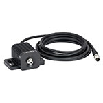
M470F3
Fiber-Coupled LEDs and Drivers
Our fiber-coupled LEDs are ideal light sources for optogenetics applications. They feature a variety of wavelength choices and a convenient interconnection to optogenetics patch cables. Thorlabs offers fiber-coupled LEDs with nominal wavelengths ranging from 280 nm to 1050 nm. See the table to the right for the LEDs with the most popular wavelengths for optogenetics. A table of compatible LED drivers can be viewed by clicking below.
| Posted Comments: | |
jcogger
(posted 2018-02-22 20:54:56.907) I am interested in buying the diffuser tips as shown on the CFDSB02. Can you explain how the diffuser works?
Thanks llamb
(posted 2018-03-08 02:44:02.0) Hello, thank you for contacting Thorlabs. The diffuser tip is integrated into the end of the fiber so that when the output light enters the high scattering cross-section, a wider output angle is achieved compared to the standard fiber material. I will reach out to you directly as well. |


Click for Details
Cross Section Drawing of OGL with CFML22L05 Cannula (Not Included)

Click for Details
Implant Guide Assembly
- Improves Adhesion and Stability During Implantation
- Compatible with Ø1.25 mm Fiber Optic Cannulae with ≥5 mm Length
- Ø3.8 mm Mounting Surface with Grooved Ring for Dental Cement
- Lightweight Surgical Titanium Construction (0.09 g)
- Weep Holes for Glue and Epoxy to Secure a Cannula
- Compatible with Stereotaxic Cannula Holders
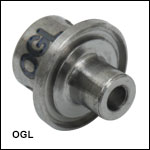
This Cannula Implant Guide is designed to provide guidance and stability for a fiber optic cannula during an implantation procedure. The bottom surface of each implant guide features a roughened surface and circular groove that increases the surface area available to dental cement and improves adhesion to the specimen. A 1.6 mm long protrusion on the implant guide helps stabilize the guide when implanted. The implant is constructed using lightweight surgical titanium (0.09 g) which can be sterilized prior to use. The OGL implant guide is compatible with our standard Ø1.25 mm cannulae (ceramic and stainless steel). When assembled, the length of the protruding fiber is reduced by 1 mm; therefore, the implant guide cannot be used with our 2 mm long cannulae. For convenience, the guide is offered in packs of one or five.
For best results when implanting a cannula, the OGL should be used with a cannula holder and stereotaxic guidance equipment. To affix the cannula within the implant guide, first insert the cannula into the receptacle of the implant guide (see drawing to the right). Then, add a small amount of cement or epoxy to the cannula via the two Ø0.8 mm weep holes. Finally, attach the cannula ferrule to an XCL cannula holder.
 Products Home


 Zoom
Zoom Fiber Optic Cannulae with Diffuser Tip