 Products Home
Fiber-Coupled LEDs for Optogenetics

- Nominal Wavelengths from 455 nm to 625 nm for Opsin Excitation
- Compatible with Optogenetics Patch Cables and Cannulae
- External Modulation Using Thorlabs' LED Drivers
M530F2
530 nm LED
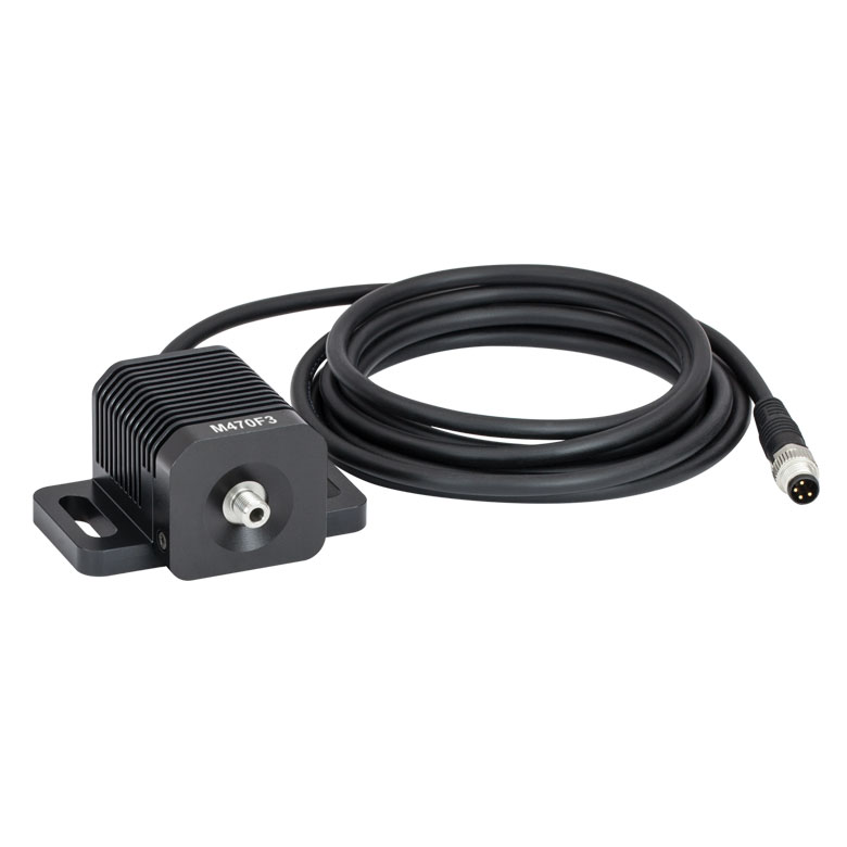
M470F3
470 nm LED
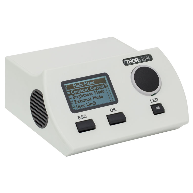
LEDD1B
Compact LED Driver
LEDs Can Deliver High-Power Light to Specimens for Exciting Neurons Using Implantable Cannulae


Please Wait
| LED Item # | Wavelengtha | Typical Opsin | Output Powerb | Color |
|---|---|---|---|---|
| M470F3 | 470 nm | ChR2, ChR2-SFO | 21.8 mW | Blue |
| M490F3 | 490 nm | Rh-CT, ChR2 (E123A) | 3.1 mW | Blue |
| M505F1 | 505 nm | ChRGR, Opto-α1AR, Opto-β2AR | 8.0 mW | Cyan |
| M530F2 | 530 nm | C1V1, VChR1 | 9.6 mW | Green |
| M565F3 | 565 nm | Arch, VChR1-SFO | 13.5 mW | Lime |
| M595F2 | 595 nm | ChR2-SFO, eNpHR3.0 | 11.5 mW | Amber |
| M625F2 | 625 nm | ReChR | 17.5 mW | Red |

Click to Enlarge
DC4100 Driver, four fiber-coupled LEDs, optogenetics patch cables, and fiber optic cannulae.
Features
- High-Power LEDs with Fiber-Coupled Outputs for Optogenetics Applications
- Wavelengths from 470 nm to 625 nm Target Common Opsins (See Table to the Right for Options)
- Compatible with Fiber Optic Cannulae and Optogenetics Patch Cables via SMA Interface
- External or Internal Modulation Using Thorlabs' LED Drivers
- Versions with FC/PC Bulkheads Available Upon Request; Contact Tech Support for Details
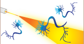
This page offers a selection of Thorlabs' fiber-coupled LEDs and drivers that are well suited for integration into optogenetics experimental setups (see photo to the right). During in vivo procedures, light from one or two LED sources are coupled into a fiber optic cannula, which is implanted in a specimen, where it is used to excite opsin proteins sensitive to the emitted light. LEDs are commonly used for these stimulation experiments as they provide high-power output over a broad range of wavelengths and exhibit superior illumination homogeneity than lasers.
The LEDs sold here feature nominal wavelengths ranging from 470 nm to 625 nm that correspond to opsins commonly used for neuron stimulation or silencing (see the Specs tab or table to the right for more information). Each fiber-coupled LED consists of a single LED that is coupled to the inserted optical fiber via butt coupling. The coupling efficiency is primarily dependent on the core diameter and the numerical aperture (NA) of the connected fiber. Larger core diameters and higher NA values give rise to reduced losses and increased output power at the end of the fiber. The spectrum of each LED and associated data file can be viewed by clicking on the links in the table to the right or in the Specs tab. Multiple windows can be opened simultaneously in order to compare LEDs.
We also offer fiber-coupled LEDs with other nominal wavelengths in addition to LEDs with a broadband white light spectrum.
Output Modulation
Neuron stimulation requires precise temporal control of the output light, typically on the order of millisecond pulses. For in vivo applications, electronic modulation of a fiber-coupled LED may be preferred over using a mechanical shutter or other modulation technique. Our fiber-coupled LEDs can be modulated in several ways when used with our LED drivers. Externally-controlled methods such as TTL use an external voltage signal to turn a light source on and off at fast switching rates (up to MHz). The DC4100 and DC4104 drivers can modulate the LED at a rate up to 100 kHz while the DC2200 can provide external modulation at up to 250 kHz. Additionally, the DC2200 driver also supports internal modulation at frequencies up to 100 kHz.The LEDD1B is capable of providing LED modulation frequencies up to 5 kHz.
Driver Options
Each LED is equipped with an integrated EEPROM (read-only memory) chip storing information about the LED (e.g., current limit, wavelength, and forward voltage) that can be read by Thorlabs' DC2200, DC4100, and DC4104 Drivers (the latter two require the DC4100-HUB). These drivers can automatically adjust the maximum current setting based on the information stored in the EEPROM chip to protect the connected LED. When using the LEDD1B T-Cube™ Driver, the current limit is set manually via an adjuster on the front of the driver.
Optogenetics Product Family for In Vivo Applications
Thorlabs offers a wide variety of products designed to support in vivo optogenetics applications. Please visit the OG Selection Guide tab above to see a full listing of available products for different applications.

| Item # | Color (Click for Spectrum and Data)a |
Nominal Wavelengtha,b |
Typical Ø200 µm Core Fiber Output Powerc |
Minimum Ø400 µm Core Fiber Output Powerd |
Typical Ø400 µm Core Fiber Output Powerd |
Maximum Current (CW) |
Forward Voltage |
Bandwidth (FWHM) |
Typical Lifetime |
|---|---|---|---|---|---|---|---|---|---|
| M470F3 | Blue | 470 nm | 7 mW | 17.2 mW | 21.8 mW | 1000 mA | 3.1 V | 20 nm | >50 000 h |
| M490F3 | Blue | 490 nm | 0.97 mW | 2.3 mW | 3.1 mW | 350 mA | 3.8 V | 26 nm | >10 000 h |
| M505F1 | Cyan | 505 nm | 2.0 mW | 7.0 mW | 8.0 mW | 1000 mA | 3.3 V | 30 nm | >50 000 h |
| M530F2 | Green | 530 nm | 3.2 mW | 6.8 mW | 9.6 mW | 1000 mA | 3.1 V | 30 nm | >50 000 h |
| M565F3e | Lime | 565 nm | 4.4 mW | 9.9 mW | 13.5 mW | 700 mA | 2.85 V | 105 nm | >10 000 h |
| M595F2e | Amber | 595 nm | 4.0 mW | 8.7 mW | 11.5 mW | 1000 mA | 3.1 V | 80 nm | >50 000 h |
| M625F2 | Red | 625 nm | 5.7 mW | 13.2 mW | 17.5 mW | 1000 mA | 2.2 V | 15 nm | >50 000 h |
| Posted Comments: | |
| No Comments Posted |
| Quick Links | |||
|---|---|---|---|
| Single-Site Stimulation | |||
| One Light Source to One Cannula Implant | |||
| Bilateral Stimulation | |||
| One Light Source to Two Cannula Implants Using Rotary Joint Splitter | |||
| One or Two Light Sources to Two Cannula Implants | |||
| Two Light Sources into One Dual-Core Cannula Implant | |||
| Illumination | |||
| Fiber-Coupled LEDs and Drivers | |||
Optogenetics Selection Guide
Thorlabs offers a wide range of optogenetics components; the compatibility of these products in select standard configurations is discussed in detail here. Please contact Technical Support for assistance with items outside the scope of this guide, including custom fiber components for optogenetics.
Single-Site Stimulation
One Light Source to One Cannula Implant
The most straightforward method for in vivo light stimulation of a specimen is to use a single fiber optic with a single LED light source. The single wavelength LED is powered by an LED driver, and then the illumination output is fiber-coupled into a patch cable, which connects to the implanted cannula. See the graphics and expandable compatibility tables below for the necessary patch cables and cannulae to create this setup. To choose the appropriate LED and driver, see below or the full web presentation.
Click on Each Component for More Information


Click to See Ø1.25 mm (LC) Ferrule Compatible Patch Cables, Cannulae, and Interconnects

Click to See Ø2.5 mm (FC) Ferrule Compatible Patch Cables, Cannulae, and Interconnects
Bilateral Stimulation
The ability to accurately and simultaneously direct light to multiple locations within a specimen is desired for many types of optogenetics experiments. For example, bilateral stimulation techniques typically target neurons in two spatially separated regions in order to induce a desired behavior. In more complex experiments involving the simultaneous inhibition and stimulation of neurons, delivering light of two different monochromatic wavelengths within close proximity enables the user to perform these experiments without implanting multiple cannulae, which can increase stress on the specimen.
Bilateral stimulation can be achieved with several different configurations depending on the application requirements. The sections below illustrate examples of different configurations using Thorlabs' optogenetics products.
Option 1: One Light Source to Two Cannula Implants Using Rotary Joint Splitter
Thorlabs' RJ2 1x2 Rotary Joint Splitter is designed for optogenetics applications and is used to split light from a single input evenly between two outputs. The rotary joint interface allows connected patch cables to freely rotate, reducing the risk of fiber damage caused by a moving specimen. See the graphic and compatibility table below for the necessary cables and cannulae to create this setup. For LEDs and drivers, see below or the full web presentation.

Click to See Ø1.25 mm (LC) Ferrule Components Recommended for Use with RJ2 Rotary Joint Splitter
Click to See Ø2.5 mm (FC) Ferrule Components Recommended for Use with RJ2 Rotary Joint Splitter
Option 2: One or Two Light Sources to Two Cannula Implants
If the intent is for one LED source to connect to two cannulae for simultaneous light modulation, then a bifurcated fiber bundle can be used to split the light from the LED into each respective cannula. For dual wavelength stimulation (mixing two wavelengths in a single cannula) or a more controlled split ratio between cannula, one can use a multimode coupler to connect one or two LEDs to the cannulae. If one cable end is left unused, the spare coupler cable end may be terminated by a light trap. See the graphic and compatibility table below for the necessary cables and cannulae to create this setup. For LEDs and drivers, see below or the full web presentation.
Click on Each Component Below for More Information


Two Light Sources into One Dual-Core Cannula Implant
For bilateral stimulation applications where the two cannulas need to be placed in close proximity (within ~1 mm), Thorlabs offers dual-core patch cables and cannulae that are designed for this specific application. Each core is driven by a separate light source, enabling users to stimulate and/or supress nerve cells in the same region of the specimen. See the graphic and compatibility table below for the necessary cables and cannulae to create this setup. For LEDs and drivers, see below or the full web presentation.

Click on Each Component for More Information
| Part Selection Table (Click Links for Item Description Popup) | |||||||||
|---|---|---|---|---|---|---|---|---|---|
| Common Fiber Properties | |||||||||
| Core Diameter | 200 µm | ||||||||
| Wavelength Range | 400 - 2200 nm | ||||||||
| NA | 0.39 | ||||||||
| Fiber Type | FT200EMT | ||||||||
| Ferrule Stylea | FC (Ø2.5 mm) | ||||||||
| Dual-Core Patch Cable | FC/PC Input | BFY32FL1 | |||||||
| SMA905 Input | BFY32SL1 | ||||||||
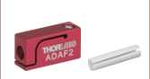
| Compatible Mating Sleeve/Interconnect | ADAF1 ADAF2 ADAF4-5 |
||||||||
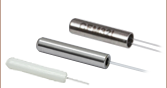
| Dual-Core Fiber Optic Cannulaec | Stainless Steel | CFM32L10 CFM32L20 |
|||||||
| Popular Fiber-Coupled LEDs for Optogenetics | ||
|---|---|---|
| Item # | M470F3 | M590F3 |
| Center Wavelength | 470 nm | 590 nm |
| Bandwidth (FWHM) | 20 nm | 16 nm |
| Typical Output Spectrum (Click to Enlarge) |
||
| Ø200 µm Core Fiber Output (Typ.)a |
7.0 mW | 1.5 mW |
| Ø400 µm Core Fiber Output (Typ.)b |
21.8 mW | 4.6 mW |
| CW Drive Current (Max) | 1.0 A | 1.0 A |
| LED Forward Voltage | 3.1 V | 2.6 V |
| Typical Lifetime | >50,000 Hours | >10,000 Hours |
Illumination
Click to Enlarge
M470F3
Fiber-Coupled LEDs and Drivers
Our fiber-coupled LEDs are ideal light sources for optogenetics applications. They feature a variety of wavelength choices and a convenient interconnection to optogenetics patch cables. Thorlabs offers fiber-coupled LEDs with nominal wavelengths ranging from 280 nm to 1050 nm. See the table to the right for the LEDs with the most popular wavelengths for optogenetics. A table of compatible LED drivers can be viewed by clicking below.
All of the drivers sold here can be used to drive the fiber-coupled LEDs sold above. The LEDD1B and DC2200 can drive up to one LED at a time, whereas the DC4100 and DC4104 can control up to four LEDs simultaneously by using the DC4100-HUB.
Each controller is capable of modulating the driven LED using an external trigger. For the DC4100 controller, all LEDs are controlled by the same modulation signal but can be individually deactivated. For the DC4104 controller, each LED is controlled by a separate modulation signal, all of which are provided through a single, included cable. The DC2200 also provides internal modulation for frequencies up to 100 kHz.
Click on the item number link below to view the complete presentation for each controller.
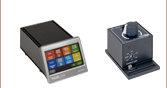
| Compatible Driversa | LEDD1Bb | DC2200c | DC4100c,d,e | DC4104c,d,e |
|---|---|---|---|---|
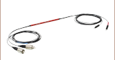
| Click Photos to Enlarge |  |
 |
 |
 |
| Main Driver Features | Very Compact Footprint 60 mm x 73 mm x 104 mm (W x H x D) |
Touchscreen Interface with Internal and External Options for Pulsed and Modulated LED Operation | 4 Channelsd | 4 Channelsd |
| LED Driver Current Output (Max) | 1.2 A | LED1 Terminal: 10.0 A LED2 Terminal: 2.0 Af |
1.0 A per Channel | 1.0 A per Channel |
| LED Driver Forward Voltage (Max) | 12 V | 50 V | 5 V | 5 V |
| Modulation Frequency (Max) | 5 kHz (External) | 20 to 100 kHz (Internal)h DC to 250 kHz (External)g,h |
100 kHz (External)h Simultaneous Across all Channels |
100 kHz (External)h Independently Controlled Channels |
| External Control Interface(s) | Analog (BNC) | USB 2.0 and Analog (BNC) | USB 2.0 and Analog (BNC) | USB 2.0 and Analog (8-Pin) |
| EEPROM Compatible: Reads Out LED Data for LED Settings | - | |||
| LCD Display | - |