Transmission and Reflection of Light Through a Wire Grid Polarizing Beamsplitter Cube
(Not to Scale)

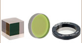
Click for DetailsEach mounted wire grid beamsplitter cube is engraved with a ray diagram for one of the two preferred entrance faces.
Features
- Transmits P-Polarized Light and Reflects S-Polarized Light
- Antireflective (AR) Coating for 400 - 700 nm (Ravg < 0.5% @ 0° AOI)
- 20.0 mm (0.79") Cube in 16 mm Cage System Compatible Mounts
- Four SM05-Threaded (0.535"-40) Ports
- High Extinction Ratio
- TP:TS > 1 000:1 (AOI: 0° - 5°)
- TP:TS > 100:1 (AOI: 0° - 25°)
Thorlabs offers a wire grid polarizing beamsplitter cube mounted in a 16 mm cage system compatible housing with SM05-threaded ports. The mounted cube consists of an array of parallel metallic wires between two N-BK7 prisms joined with optical cement. Wire grid polarizers transmit radiation with an electric field vector perpendicular to the wire and reflect radiation with the electric field vector parallel to the wire. This cube separates the s- and p-polarized components by reflecting the s-polarized component at the wire grid, while allowing the p-polarized component to pass. Due to surface reflections, the reflected beam contains both polarizations.
This beamsplitter cube has a larger Angle of Incidence (AOI) than traditional broadband polarizing beamsplitter cubes. For the highest polarization extinction ratio, use the transmitted beam, which offers an extinction ratio of TP:TS > 1 000:1 for an AOI from 0° to 5°. For higher AOI (5° to 25°), this cube can maintain an extinction ratio of TP:TS > 100:1. These beamsplitter cubes are coated with an AR thin film designed for 400 - 700 nm (Ravg < 0.5% @ 0° AOI).
The wire grid is sandwiched between the hypotenuses of the two prisms that make up the cube. Then, optical cement is used to bind the two prism halves together (refer to the diagram above). Light can be input into any of the polished faces to separate the s- and p-polarizations. One possible orientation is engraved on the top of the cage cube.
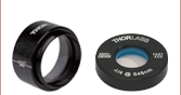
A bottom-located 8-32 or M4 tap is included on each housing for post mounting. The housing features four SM05-threaded entrance and exit ports for compatibility with our SM05 (0.535"-40) lens tubes. Four 4-40 tapped holes surrounding each port provide compatibility with our 16 mm cage systems. These mounted beamsplitters can be connected to other cage cubes through the use of our cage rods and SRSCA adapters.
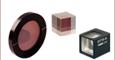
We also offer unmounted versions of our wire grid beamsplitters in various sizes. Custom beamsplitter cubes can be ordered by contacting Tech Support. For high-power applications, we also offer high-power polarizing beamsplitting cubes that have damage thresholds greater than 10 J/cm2. We also offer polarizing beamsplitter cubes at laser line wavelengths, which have a high extinction ratio of >3 000:1 (TP:TS).
| Item # |
CCM5-WPBS20 |
| Design Wavelength |
400 - 700 nm |
| AR Coating |
Ravg < 0.5% @ 0° AOI for 400 - 700 nm |
| Material |
N-BK7 |
| Extinction Ratioa |
Tp:Ts > 1 000:1 @ 0° - 5° AOI
Tp:Ts > 100:1 @ 0° - 25° AOI |
| Transmission |
Tp > 75% (Avg.) @ 0° AOI for 400 - 700 nm |
| Reflectance |
Rs > 70% @ 0° - 25° AOI for 400 - 700 nm |
| Transmitted Beam Deviation |
<20 arcmin |
| Reflected Beam Deviation |
90° ± 20 arcmin |
| Clear Aperture |
Ø12.5 mm |
| Transmitted Wavefront Error |
<λ/4 @ 633 nm |
| Surface Quality |
40-20 Scratch-Dig |
| Dimensions (L × W × H) |
1.18" x 1.18" x 1.18" (30.0 mm x 30.0 mm x 30.0 mm) |
| Post Mount |
8-32 |

Click to Enlarge
Click for Raw Data
The graph above shows the measured extinction ratio (ER) for transmitted light for light incident upon one of the entrance faces. The extinction ratio (also known as contrast) is the ratio of the maximum transmission of a sufficiently linearly polarized signal when the polarizer’s axis is aligned with the signal to the minimum transmission when the polarizer is rotated by 90°. The plotted data is given for AOIs of 0° and ±25°.

Click to Enlarge
Click for Raw Data
The graph above shows the measured transmission through the wire grid polarizing cube for p-polarized light for light incident upon one of the entrance faces. The plotted data is given for AOIs of 0° and ±25°.

Click to Enlarge
Click for Raw Data
The graph above shows the measured transmission through the wire grid polarizing cube for s-polarized light for light incident upon one of the entrance faces. The plotted data is given for AOIs of 0° and ±25°.

Click to Enlarge
Click for Raw Data
The graph above shows the measured reflectance from the wire grid polarizing cube for p-polarized light for light incident upon one of the entrance faces. The plotted data is given for AOIs of 0° and ±25°.

Click to Enlarge
Click for Raw Data
The graph above shows the measured reflectance from the wire grid polarizing cube for s-polarized light for light incident upon one of the entrance faces. The plotted data is given for AOIs of 0° and ±25°.
Polarizer Selection Guide
Thorlabs offers a diverse range of polarizers, including wire grid, film, calcite, alpha-BBO, rutile, and beamsplitting polarizers. Collectively, our line of wire grid polarizers offers coverage from the visible range to the beginning of the Far-IR range. Our nanoparticle linear film polarizers provide extinction ratios as high as 100 000:1. Alternatively, our other film polarizers offer an affordable solution for polarizing light from the visible to the Near-IR. Next, our beamsplitting polarizers allow for use of the reflected beam, as well as the more completely polarized transmitted beam. Finally, our alpha-BBO (UV), calcite (visible to Near-IR), rutile (Near-IR to Mid-IR), and yttrium orthovanadate (YVO4) (Near-IR to Mid-IR) polarizers each offer an exceptional extinction ratio of 100 000:1 within their respective wavelength ranges.
To explore the available types, wavelength ranges, extinction ratios, transmission, and available sizes for each polarizer category, click More [+] in the appropriate row below.
| Polarizer Type |
Wavelength Range |
Extinction Ratio |
Transmissiona |
Available Sizes |
| Wire Grid Polarizers on Glass Substrates |
420 nm - 700 nm |
>800:1
(Avg. Over Wavelength Range) |
 |
12.5 mm x 12.5 mm, Ø25.0 mmb,
25.0 mm x 25.0 mm,
and 50.0 mm x 50.0 mm |
| 250 nm - 4 µm |
>10:1 from 250 nm - 4 µm
>100:1 from 300 nm - 4 µm
>1000:1 from 600 nm - 4 µm
>10 000:1 from 2.25 µm - 4 µm |
|
12.5 mm x 12.5 mm, Ø25.0 mmb,
25.0 mm x 25.0 mm,
and 50.0 mm x 50.0 mm |
Wire Grid Polarizing Beamsplitter Cubes
(Unmounted, 16 mm Cage Cube, or 30 mm Cage Cube) |
400 nm - 700 nm |
>1 000:1 (AOI: 0° - 5°)
>100:1 (AOI: 0° - 25°) |
P-Pol.
S-Pol. |
20 mm and 1"e |
| Holographic Wire Grid Polarizers |
2 µm - 12 µm |
150:1 at 3 µm
300:1 at 10 µm |
|
Ø25.0 mmb and Ø50.0 mmb |
| 2 µm - 9 µm |
150:1 at 3 µm
300:1 at 8 µm |
| 2 µm - 30 µm |
150:1 at 3 µm
300:1 at 15 µm |
| 2 µm - 18 µm |
150:1 at 3 µm
300:1 at 10 µm |
| MIR Wire Grid Polarizers on Silicon Substrates |
3 µm - 5 µm |
>1000:1 |
|
12.5 mm x 12.5 mmb, Ø25.0 mmb,
25.0 mm x 25.0 mmb,
and 50.0 mm x 50.0 mmb |
| 7 µm - 15 µm |
>10,000:1 |
|
12.5 mm x 12.5 mmb, Ø25.0 mmb,
25.0 mm x 25.0 mmb,
and 50.0 mm x 50.0 mmb |
| Polarizer Type |
Wavelength Range |
Extinction Ratio |
Transmissiona |
Available Sizes |
| Nanoparticle Linear Film Polarizers |
365 nm - 395 nm |
>1000:1 from 365 nm - 395 nm
>10 000:1 from 369 nm - 390 nm
>100 000:1 from 372 nm - 388 nm |
|
Ø12.5 mmc and Ø25.0 mmd |
| 480 nm - 550 nm |
>10 000:1 from 480 nm - 550 nm |
|
Ø12.5 mmc and Ø25.0 mmd |
| 510 nm - 800 nm |
>1000:1 from 510 nm - 800 nm
>10 000:1 from 520 - 740 nm
>100 000:1 from 530 - 640 nm |
|
Ø12.5 mmc and Ø25.0 mmd |
| 550 nm - 1500 nm |
>10 000:1 from 550 nm - 1500 nm
>100 000:1 from 600 nm - 1200 nm |
|
Ø12.5 mmc and Ø25.0 mmd |
| 650 nm - 1100 nm |
>200:1 from 650 nm - 695 nm
>1000:1 from 695 nm - 1100 nm |
|
Ø1/2"c and Ø1"d |
| 650 nm - 2000 nm |
>1000:1 from 650 nm - 2000 nm
>10 000:1 from 750 nm - 1800 nm
>100 000:1 from 850 nm - 1600 nm |
|
Ø12.5 mmc and Ø25.0 mmd |
| 1 µm - 3 µm |
>1000:1 from 1 µm - 3 µm
>10,000:1 from 1.2 µm - 3 µm |
|
Ø12.5 mmc and Ø25.0 mmd |
| 1.1 µm - 1.8 µm |
>1000:1 from 1.1 µm - 1.8 µm |
|
Ø1/2"c and Ø1"d |
| 1.5 µm - 5 µm |
>1000:1 from 1.5 µm - 5 µm
>10 000:1 from 2 µm - 4.5 µm |
|
Ø12.5 mmc and Ø25.0 mmd |
| Economy Film Polarizers |
400 nm - 700 nm |
>100:1 from 400 nm - 500 nm
>1000:1 from 500 nm - 700 nm
>5000:1 from 530 nm - 690 nm |
|
2" x 2" |
| 600 nm - 1100 nm |
>400:1 from 600 nm - 1100 nm
>1000:1 from 600 nm - 940 nm |
|
2" x 2" |
| Economy Laminated Film Polarizers |
400 nm - 700 nm |
>100:1 from 400 nm - 500 nm
>1000:1 from 500 nm - 700 nm
>5000:1 from 530 nm - 690 nm |
|
Ø1/2", Ø1", and Ø2" |
| 600 nm - 1100 nm |
>1000:1 from 600 nm - 950 nm
>400:1 from 600 nm - 1100 nm |
|
Ø1/2", Ø1", and Ø2" |
| 1050 nm - 1700 nm |
>1000:1 from 1050 - 1400 nm
>2000:1 from 1400 - 1700 nm |
|
Ø1/2", Ø1", and Ø2" |
| Polarizer Type |
Wavelength Range |
Extinction Ratio |
Transmissiona |
Available Sizes |
| Polarizing Plate Beamsplitters |
405 nm |
>10 000:1 |
|
Ø1" and 25 mm x 36 mm |
| 532 nm |
|
| 633 nm |
|
| 780 nm |
|
| 808 nm |
|
| 1030 nm |
|
| 1064 nm |
|
| 1310 nm |
|
| 1550 nm |
|
| Polarizing Bandpass Filters |
355 nm +6 nm / -9 nm |
1 000 000:1 |
|
25.2 mm x 35.6 mm |
Broadband Polarizing Beamsplitter Cubes
(Unmounted, 16 mm Cage Cube, or 30 mm Cage Cube) |
420 nm - 680 nm |
1000:1 |
|
5 mm, 10 mm, 1/2", 20 mme, 1"e, and 2" |
| 620 nm - 1000 nm |
|
| 900 nm - 1300 nm |
|
| 1200 nm - 1600 nm |
|
Wire Grid Polarizing Beamsplitter Cubes
(Unmounted, 16 mm Cage Cube, or 30 mm Cage Cube) |
400 nm - 700 nm |
>1 000:1 (AOI: 0° - 5°)
>100:1 (AOI: 0° - 25°) |
P-Pol.
S-Pol. |
10 mm, 20 mme, and 1"e |
Laser-Line Polarizing Beamsplitter Cubes
(Unmounted or 30 mm Cage Cube) |
532 nm |
3000:1 |
|
10 mm, 1/2", 1"e |
| 633 nm |
|
| 780 nm |
|
| 980 nm |
|
1"e |
| 1064 nm |
|
10 mm, 1/2", 1"e |
| 1550 nm |
|
| High-Power Laser-Line Polarizing Beamsplitter Cubes (Unmounted or 30 mm Cage Cube) |
355 nm |
2000:1 |
|
1/2" and 1"e |
| 405 nm |
|
| 532 nm |
|
| 633 nm |
|
| 780 - 808 nm |
|
| 1064 nm |
|
| Calcite Beam Displacers |
350 nmf - 2.3 µm (Uncoated) |
- |
|
10 mmb
(Clear Aperture, Square) |
| Yttrium Orthovanadate (YVO4) Beam Displacers |
488 nm - 3.4 µm (Uncoated) |
- |
|
>3 mm x 5 mm Ellipseg
(Clear Aperture) |
| 2000 nm (V Coated) |
| Polarizer Type |
Wavelength Range |
Extinction Ratio |
Transmissiona,h |
Available Sizes |
| Glan-Laser Calcite Polarizers |
350 nmf - 2.3 µm (Uncoated) |
100 000:1 |
|
5 mmb, 10 mmj, and 15 mmb
(Clear Aperture, Square) |
| 350 nmf - 700 nm (A Coated) |
| 650 nm - 1050 nm (B Coated) |
| 1050 nm - 1700 nm (C Coated) |
| 1064 nm (V Coated)i |
| Glan-Taylor Calcite Polarizers |
350 nmf - 2.3 µm (Uncoated) |
5 mmb, 10 mmb, and 15 mmb
(Clear Aperture, Square) |
| 350 nmf - 700 nm (A Coated) |
| 650 nm - 1050 nm (B Coated) |
| 1050 nm - 1700 nm (C Coated) |
Glan-Thompson Calcite Polarizers
(Unmounted or Mounted) |
350 nmf - 2.3 µm (Uncoated) |
5 mmj and 10 mmj
(Clear Aperture, Square) |
| 350 nmf - 700 nm (A Coated) |
| 650 nm - 1050 nm (B Coated) |
| Double Glan-Taylor Calcite Polarizers |
350 nmf - 2.3 µm (Uncoated) |
9 mmb
(Clear Aperture, Square) |
| Beam Displacers |
350 nmf - 2.3 µm (Uncoated) |
10 mmb
(Clear Aperture, Square) |
| Wollaston Prism Polarizers |
350 nmf - 2.3 µm (Uncoated) |
Ø10 mmj
(Clear Aperture) |
| 350 nmf - 700 nm (A Coated) |
| 650 nm - 1050 nm (B Coated) |
| Polarizer Type |
Wavelength Range |
Extinction Ratio |
Transmissiona |
Available Sizes |
| Wollaston Prism Polarizers |
400 nm - 2000 nm |
10 000:1 |
|
Ø10 mmb
(Clear Aperture) |
| Polarizer Type |
Wavelength Range |
Extinction Ratio |
Transmissiona |
Available Sizes |
| Beam Displacers |
488 nm - 3.4 µm (Uncoated)
2000 nm (V Coated) |
100 000:1 |
|
>3 mm x 5 mm
(Clear Aperture, Ellipse) |
| Wollaston Prism Polarizers |
900 nm - 3.24 µm |
|
Ø10 mmb
(Clear Aperture) |
| Rochon Prism Polarizers |
488 nm - 3.4 µm |
10 mm x 10 mmb
(Clear Aperture) |
| Polarizer Type |
Wavelength Range |
Extinction Ratio |
Transmissiona |
Available Sizes |
| Rutile TiO2 Polarizers |
2.2 µm - 4 µm |
100 000:1 |
|
9.1 mm x 9.5 mm x 9.5 mmb and
10.7 mm x 15.9 mm x 15.9 mmb |
Thorlabs' portfolio contains many different kinds of beamsplitters, which can split beams by intensity or by polarization. We offer plate and cube beamsplitters, though other form factors exist, including pellicle and birefringent crystal. Many of our beamsplitters come in premounted or unmounted variants. Below is a complete listing of our beamsplitter offerings. To explore the available types, wavelength ranges, splitting/extinction ratios, transmission, and available sizes for each beamsplitter category, click More [+] in the appropriate row below.
Non-Polarizing Beamsplitters
| Type |
Wavelength Range |
Splitting Ratio
(R:T) |
Typical Reflectancea
(Click for Plot) |
Typical Transmissiona
(Click for Plot) |
Available Sizes
(Unmounted) |
| Economy |
450 - 650 nm |
30:70 |

|
Ø1" and Ø2" |
| 50:50 |
|
UV Fused Silica
for UV |
250 - 450 nm |
50:50 |
|
|
Ø1/2", Ø1",
25 x 36 mm, and Ø2" |
UV Fused Silica
for UV to NIR |
350 - 1100 nm |
50:50 |
|
|
Ø1/2", Ø1",
25 x 36 mm, and Ø2" |
| UV Fused Silica for Visible |
400 - 700 nm |
10:90 |
|
|
Ø1/2", Ø1",
25 x 36 mm, and Ø2" |
| 30:70 |
|
|
| 50:50 |
|
|
| 70:30 |
|
|
| 90:10 |
|
|
UV Fused Silica
for Visibile to IR |
600 - 1700 nm |
50:50 |
|
|
Ø1/2", Ø1",
25 x 36 mm, and Ø2" |
| UV Fused Silica for NIR |
700 - 1100 nm |
10:90 |
|
|
Ø1/2", Ø1",
25 x 36 mm, and Ø2" |
| 30:70 |
|
|
| 50:50 |
|
|
| 70:30 |
|
|
| 90:10 |
|
|
| IR Fused Silica for IR |
0.9 - 2.6 µm |
50:50 |
|
|
Ø1/2", Ø1",
25 x 36 mm, and Ø2" |
| UV Fused Silica for NIR |
1.2 - 1.6 µm |
10:90 |
|
|
Ø1/2", Ø1",
25 x 36 mm, and Ø2" |
| 30:70 |
|
|
| 50:50 |
|
|
| 70:30 |
|
|
| 90:10 |
|
|
| CaF2 for IR |
1.0 - 6.0 µm |
50:50 |
|
|
Ø1/2", Ø1", 25 x 36 mm, and Ø2" |
| 2.0 - 8.0 µm |
|
|
Ø1/2", Ø1", and Ø2" |
| ZnSe for IR |
1.0 - 12.0 µm |
50:50 |
|
|
Ø1" |
| 7.0 - 14.0 µm |
|
|
Ø1/2", Ø1", and Ø2" |
| Laser Line for Nd: YAG |
532 nm |
50:50 |
|
|
Ø1/2", Ø1",
25 x 36 mm, and Ø2" |
| 1064 nm |
|
|
| Polka Dot |
250 nm - 2.0 µm |
50:50 |
0° and 8°
45° |
Ø1", 1" x 1", and Ø2" |
| 350 nm - 2.0 µm |
0° and 8°
45° |
Ø1", 1" x 1", and Ø2" |
| 180 nm - 8.0 µm |
0° and 12°
45° |
Ø1" and Ø2" |
| 2.0 - 11.0 µm |
0° and 10°
45° |
Ø1" |
| Ultrafast with Low GDD |
600 - 1500 nm |
20:80 |
|
Ø1" |
| 50:50 |
|
| 80:20 |
|
| Type |
Wavelength Range |
Splitting Ratio
(R:T) |
Typical Transmission
(Click for Plot) |
Available Cube Side Length |
Visible:
Unmounted
16 mm Cage Cube
30 mm Cage Cube |
400 - 700 nm |
10:90 |
|
Unmounted:
5 mm, 10 mm, 1/2", 20 mm, 1" |
| 30:70 |
|
Unmounted:
5 mm, 10 mm, 1/2", 20 mm, 1" |
| 50:50 |
|
Unmounted:
5 mm, 10 mm, 1/2",
20 mm, 1", and 2"
Mounted:
20 mm in a 16 mm Cage Cube,
1" in a 30 mm Cage Cube
|
| 70:30 |
|
Unmounted:
5 mm, 10 mm, 1/2", 20 mm, 1" |
| 90:10 |
|
Unmounted:
5 mm, 10 mm, 1/2", 20 mm, 1" |
NIR:
Unmounted
16 mm Cage Cube
30 mm Cage Cube |
700 - 1100 nm |
10:90 |
|
Unmounted:
5 mm, 10 mm, 1/2", 20 mm |
| 30:70 |
|
Unmounted:
5 mm, 10 mm, 1/2", 20 mm, 1" |
| 50:50 |
|
Unmounted:
5 mm, 10 mm, 1/2",
20 mm, 1", and 2"
Mounted:
20 mm in a 16 mm Cage Cube,
1" in a 30 mm Cage Cube |
| 70:30 |
|
Unmounted:
5 mm, 10 mm, 1/2", 20 mm, 1" |
| 90:10 |
|
Unmounted:
5 mm, 10 mm, 1/2", 20 mm, 1" |
IR:
Unmounted
16 mm Cage Cube
30 mm Cage Cube |
1100 - 1600 nm |
10:90 |
|
Unmounted:
5 mm, 10 mm, 1/2", 20 mm |
| 30:70 |
|
Unmounted:
5 mm, 10 mm, 1/2", 20 mm |
| 50:50 |
|
Unmounted:
5 mm, 10 mm, 1/2",
20 mm, 1", and 2"
Mounted:
20 mm in a 16 mm Cage Cube,
1" in a 30 mm Cage Cube |
| 70:30 |
|
Unmounted:
5 mm, 10 mm, 1/2", 20 mm, 1" |
| 90:10 |
|
Unmounted:
5 mm, 10 mm, 1/2", 20 mm,1" |
| Type |
Wavelength Range |
Splitting Ratio
(R:T) |
Typical Reflectancea
(Click for Plot) |
Typical Transmissiona
(Click for Plot) |
Available Sizes |
Pellicle
Unmounted
30 mm Cage Cube |
400 - 2400 nm |
8:92 |
|
|
Unmounted:
Ø1/2", Ø1", and Ø2"
Mounted:
Ø1" in a 30 mm Cage Cube |
| 300 - 400 nm |
45:55 |
|
|
Unmounted:
Ø1" and Ø2"
Mounted:
Ø1" in a 30 mm Cage Cube |
| 400 - 700 nm |
45:55 |
|
|
Unmounted:
Ø1/2", Ø1", and Ø2"
Mounted:
Ø1" in a 30 mm Cage Cube |
| 635 nm |
33:67 |
|
|
Unmounted:
Ø1/2", Ø1", Ø2"
Mounted:
Ø1" in a 30 mm Cage Cube |
| 635 nm |
50:50 |
|
|
Unmounted:
Ø1/2", Ø1", and Ø2"
Mounted:
Ø1" in a 30 mm Cage Cube |
| 700 - 900 nm |
45:55 |
|
|
Unmounted:
Ø1/2", Ø1", and Ø2"
Mounted:
Ø1" in a 30 mm Cage Cube |
| 1.0 - 2.0 µm |
45:55 |
|
|
Unmounted:
Ø1/2", Ø1", and Ø2"
Mounted:
Ø1" in a 30 mm Cage Cube |
| 3.0 - 5.0 µm |
45:55 |
|
|
Unmounted:
Ø1/2" and Ø1"
Mounted:
Ø1" in a 30 mm Cage Cube |
Polarizing Beamsplitters
| Type |
Center Wavelength |
Extinction Ratio
(TP:TS) |
Typical Transmission
(Click for Plot) |
Available Sizes
(Unmounted) |
| Standard |
405 nm |
>10 000:1 |
|
Ø1" and 25 mm x 36 mm |
| 532 nm |
|
| 633 nm |
|
| 780 nm |
|
| 808 nm |
|
| 1030 nm |
|
| 1064 nm |
|
| 1310 nm |
|
| 1550 nm |
|
Polarizing
Bandpass Filters |
355 nm |
1 000 000:1 |
|
25.2 mm x 35.6 mm |
| Type |
Wavelength Range |
Extinction Ratio
(TP:TS) |
Typical Transmission |
Available Cube Side Length |
Standard:
Unmounted
16 mm Cage Cube
30 mm Cage Cube |
420 - 680 nm |
>1 000:1 |
|
Unmounted:
5 mm, 10 mm, 1/2",
20 mm, 1", and 2"
Mounted:
20 mm in a 16 mm Cage Cube,
1" in a 30 mm Cage Cube |
| 620 - 1000 nm |
|
| 900 - 1300 nm |
|
| 1200 - 1600 nm |
|
Wire Grid:
Unmounted
16 mm Cage Cube
30 mm Cage Cube |
400 - 700 nm |
>1 000:1 (AOI: 0° - 5°)
>100:1 (AOI: 0° - 25°)
|
P-Pol.
S-Pol. |
Unmounted:
1"
Mounted:
20 mm in a 16 mm Cage Cube,
1" in a 30 mm Cage Cube |
High-Power Laser Line:
Unmounted
30 mm Cage Cube |
355 nm |
>2 000:1 |
|
Unmounted:
1/2" and 1"
Mounted:
1" in a 30 mm Cage Cube
|
| 405 nm |
|
| 532 nm |
|
| 633 nm |
|
| 780 - 808 nm |
|
| 1064 nm |
|
Laser Line:
Unmounted
30 mm Cage Cube |
532 nm |
>3 000:1 |
|
Unmounted:
10 mm, 1/2", and 1"
Mounted:
1" in a 30 mm Cage Cube |
| 633 nm |
|
| 780 nm |
|
| 980 nm |
|
| 1064 nm |
|
| 1550 nm |
|
| Laser-Line Variable |
532 nm |
Not Specified |
No Graph Available |
Assembly Mounted
in a 30 mm Cage Cube |
| 633 nm |
| 780 nm |
| 1064 nm |
| 1550 nm |
| Broadband Variable |
420 - 680 nm |
Not Specified |
No Graph Available |
Assembly Mounted
in a 30 mm Cage Cube |
| 690 - 1000 nm |
| 900 - 1200 nm |
| 1200 - 1600 nm |
Circular
Polarizer/Beamsplitter |
532 nm |
Not Specified |
No Graph Available |
Assembly Mounted
in a 30 mm Cage Cube |
| 633 nm |
| 780 nm |
| 1064 nm |
| 1550 nm |
| Type |
Wavelength Range |
Extinction Ratio
(TP:TS) |
Beam Separation Angle (Typical) |
Typcial Substrate
Transmission
(Click for Plot) |
Typical Coating
Reflectance
(Click for Plot) |
Available Sizes |
| Calcite Beam Displacers |
350 nm - 2.3 µm |
Not Specified
|
Parallel with 2.7 mm Spacing at 1500 nm |
|
Uncoated |
10 mma
(Clear Aperture, Square) |
Parallel with 4.0 mm
Spacing at 1500 nm |
10 mma
(Clear Aperture, Square) |
| Yttrium Orthovanadate Beam Displacer |
488 nm - 3.4 µm |
Not Specified |
Parallel with 1.2 mm
Spacing at 2000 nm |
|
Uncoated |
>3 mm x 5 mmb
(Clear Aperture, Ellipse) |
| 2.0 µm |
|
| Wollaston Prisms |
400 nm - 2.0 µm |
>10 000:1 |
1° at 633 nm |
|
Uncoated |
Ø10 mma
(Clear Aperture) |
| 200 nm - 6.0 µm |
>10 000:1 |
1° 20' at 633 nm |
|
Uncoated |
Ø10 mma
(Clear Aperture) |
| 190 nm - 3.5 µm |
>100 000:1 |
20° at 250 nm |
|
Protective MgF2
(No Data) |
Ø10 mma
(Clear Aperture) |
| 350 nm - 2.3 µm |
>100 000:1 |
20° at 633 nm |
|
Uncoated |
Ø10 mmb
(Clear Aperture) |
|
Ø10 mma
(Clear Aperture) |
Ø10 mma
(Clear Aperture) |
| 900 nm - 3.4 µm |
>100 000:1 |
20° at 633 nm |
|
Uncoated |
Ø10 mma
(Clear Aperture) |
| Rochon Prisms |
200 nm - 6.0 µm |
>10 000:1 |
1.5° at 4 µm |
|
Uncoated |
10 mm x 10 mma
(Min. Clear Aperture) |
| 488 nm - 3.4 µm |
>100 000:1 |
10.6° at 2 µm |
|
Glan-Laser
α-BBO Polarizers |
210 - 450 nm |
>100 000:1 |
119° |
|
|
5 mma and 10 mma
(Clear Aperture, Square) |
| 220 - 370 nm |
|
| 405 nm |
|
| Glan-Laser Calcite Polarizers |
350 nm - 2.3 µm |
100 000:1 |
112° |
|
|
5 mma, 10 mmb, and 15 mma
(Clear Aperture, Square) |
| 350 - 700 nm |
| 650 - 1050 nm |
| 1050 - 1700 nm |
| 1064 nm |
| Glan-Taylor Polarizers |
350 nm - 2.3 µm |
100 000:1 |
112° |
|
|
5 mma, 10 mma, and 15 mma
(Clear Aperture, Square) |
| 350 - 700 nm |
| 650 - 1050 nm |
| 1050 - 1700 nm |
Other Beamsplitters
| Type |
Wavelength Range |
Splitting Ratio |
Substrate Transmission |
Typical Reflectance |
Available Sizes
(Unmounted) |
| Wedged Plate Beamsplitter |
185 nm - 2.1 µm |
- |
|
- |
2" x 1" (L x H)
8.0 mm (Middle Thickness)
Wedge Angle: 5° |
| Brewster Windows |
185 nm - 2.1 µm |
- |
|
|
6.0 mm, 8.0 mm, 13.0 mm, 16.0 mm,
20.0 mm, and 25.0 mm
(Minor Diameters) |
 Products Home / Polarization Optics / Polarizers / Polarizing Beamsplitters / Polarizing Beamsplitting Cubes / Wire Grid Beamsplitter Cube in 16 mm Cage Cube