 Products Home
Optical Shutters
- Ø1/2" and Ø1" Beam Shutters
- Two Controller Options Available
- Interlock Mode Incorporated into Control Logic
SH1
Ø1" Beam Shutter,
<10 ms Close Activation Time
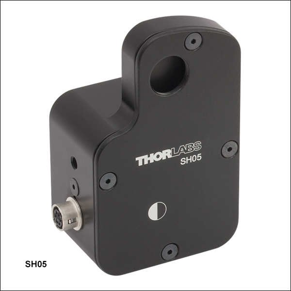
SH05
Ø1/2" Beam Shutter,
≤4.08 ms Close Activation Time
KSC101
K-Cube Compact Shutter Controller
(Compatible with the SH05 Optical Beam Shutter)
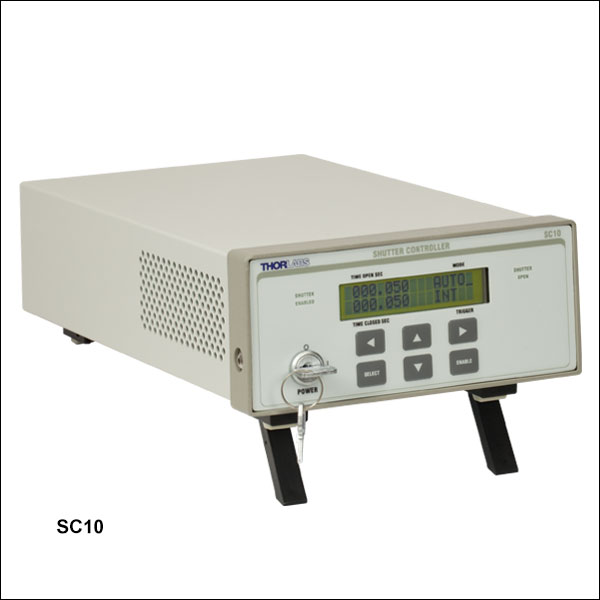
SC10
Benchtop Shutter Controller


Please Wait

| Shutter Selection Guide | |
|---|---|
| Diaphragm | Single-Blade |
| Ø1/4", Ø1/2", and Ø1" Motorized |
Ø0.29" Manual |
| Ø1/2" and Ø1" Motorized |
|
Features
- Ø1/2" and Ø1" Beam Shutters
- Close Activation Times of ≤4.08 ms or <10 ms Available
- Passive Closure Mechanism Ideal for Laser Safety Applications
- One 8-32 (M4) Tap on Three Sides for Ø1/2" Post Mounting
- Benchtop or Compact Controller Options (Sold Separately Below)
Thorlabs' Optical Shutters utilize a rotary, electro-mechanical actuator to provide millisecond shutter operation. During operation, these shutters remain in a closed position and then open when a pulse control signal is applied by an external controller. As long as the control voltage to the optical shutter remains high, the shutter stays open, but as soon as the voltage goes low, the shutter closes, providing inherent "fail-safe" operation. The frequency at which the device is opened and closed can be controlled. An optical sensor, which detects the shutter blade position in the housing, provides information that confirms the state of the optical shutter position. This makes it ideal in applications where a laser safety lockout is required.
In order to ensure that your optical shutter has a long lifetime, the aperture should not be located near the focus of a laser beam. Please note that the solenoid's performance is not guaranteed if the case temperature exceeds 50 °C. Significant heat buildup will occur if the aperture is closed for a long time while a high-power laser is incident on the shutter.
Controller Options
Thorlabs offers two controllers for use with our optical shutters, the SC10 and KSC101. The SC10 can be used with the SH05(/M) or the SH1(/M), while the KSC101 is only compatible with the SH05(/M). The SH1 can also be used with a third-party controller. For information on the control requirements, please see the Specs tab. Both controllers include an "interlock mode" that is incorporated into the controller's logic; a physical key lock; and manual, triggered, or sofwtare controlled operation modes. The SC10 is a benchtop controller with an RS-232 computer connection that allows the controller to be operated using the included standalone software GUI. The KSC101 is a compact K-Cube™ controller with a USB 3.0 (2.0 Compliant) computer connection that allows the controller to be controlled using Thorlabs' Kinesis® or legacy APT™ software packages. See the Specs tab for a comparison table of the two controller options.
A 10-foot-long cable with 6-way HRS connector is included for connecting the shutter to either the SC10 or KSC101 Shutter Controller. A replacement cable can also be purchased below.
| Controller Specifications | |||
|---|---|---|---|
| Item # | SC10 | KSC101 | |
| Maximum Exposure Ratea | 25 Hz | 20 Hz | |
| Minimum Exposure Timeb | 10 ms | 15 ms | |
| Typical Transfer Time | 1 ms | 1.5 ms | |
| Accuracy | 0.2 ms | 0.3 ms (at 15 ms Exposure) | |
| On/Off Timesb,c | 1 ms to 999.99 s | 10 ms to 1000 s | |
| Maximum Steady State Power | 5 W | 3.5 W | |
| Hold Voltage Range | 9 to 11.8 V | 6.5 to 7.5 Avg. Volts PWM | |
| Trigger Input/Output | - | TTL | |
| Voltage Output | 24 V Pulse (10 V Hold) | 15 V Max (7 V Avg. PWM Hold) | |
| Output Enable | Key Switch with Interlock Connector | Key Switch and Interlock Jack Plug | |
| Operating Modes | |||
| Manual | User Controlled On/Off | ||
| Single | Trigger Controlled Single On/Off Cycles | DSP Controlled Single On/Cycles | |
| Auto | Trigger Controlled Multiple On/Off Cycles | DSP Controlled Multiple On/Off Cycles | |
| X-Gate (Triggered) | Shutter Controlled by BNC Input Trigger | Externally Triggered On/Off | |
| Trig IN (Trig 1d) | BNC, TTL, 2.2 - 5 V | SMA, TTL, Type 5 V | |
| Trig OUT (Trig 2d) | BNC, TTL, 2.2 - 5 V | SMA, TTL, Type 5 V | |
| Output (6 Way Hirose) | |||
| Solenoid Drive | 24 V Pulse (10 V Hold) | 15 V Regulated DC | |
| Position Feedback Sensor | - | Photodiode | |
| Input Power Requirements | |||
| Voltage | 100 - 240 VAC U.S. Power Cord Included |
15 V Regulated DC | |
| Current | - | 1 A Peak, 300 mA Steady State | |
| General | |||
| Instrument Weight | 5 lbs (2 kg) | 160 g (5.5 oz) | |
| Housing Dimensions (W x D x H) |
11.5" x 5.3" x 3.0" (292 mm x 135 mm x 76 mm) |
60.0 x 60.0 x 49.2 mm (2.36 " x 2.36 " x 1.94")e |
|
| Beam Shutter Specifications | ||
|---|---|---|
| Item # | SH05(/M) | SH1(/M) |
| Aperture | Ø0.5" (12.7 mm) | Ø1.0" (25.4 mm) |
| Blade Material | 6061-T6 Aluminum | |
| Blade Thickness | 0.06" (1.6 mm) | |
| Solenoid Coil Resistance | 28 Ω | 31.84 Ω |
| Initial State | Closed | |
| Operation | ||
| Actuation Pulse | 8 V to 50 V (Time Dependent) |
10 V to 75 V (Time Dependent) |
| Holding Voltage | 8 V to 12 V | 8 V to 15 V |
| Maximum Recommended Applied Solenoid Voltagea |
<12 VDC (Holding) <50 VDC (Pulse) |
15 VDC (Holding) 75 VDC (Pulse) |
| Maximum Pulse Rate | 10 Hz Steady, 25 Hz Burst | 12.5 Hz Steady, 16.6 Hz Burst |
| Duty Cycleb | Optimum @ 10 Hz = 40% | Optimum @ 8 Hz = 50% |
| Lifetime | 1,000,000 Cycles (Typical) | |
| Max Solenoid Power (20°C) | ||
| Steady State | 4 W @ Continuous | 9 W @ Continuous |
| 50% Duty Cycle | 8 W @ 100 s | 18 W @ 100 s |
| 25% Duty Cycle | 16 W @ 36 s | 36 W @ 36 s |
| 5% Duty Cycle | 80 W @ 2.5 s | 180 W @ 2.8 s |

| Timing Specifications | |||
|---|---|---|---|
| Controller | Eventa | SH05(/M) | SH1(/M) |
| SC10 | TI | 8.0 ms | 10 ms |
| TO | 3.0 ms | 10 ms | |
| TD/R | 13.0 ms | 20 ms | |
| TC | 4.08 ms | 10 ms | |
| MOP | 10 ms | 40 ms | |
| MSOP | 27.0 ms | 40 ms | |
| KSC101 | TI | 13 ms | N/Ab |
| TO | 1 ms | ||
| TD/R | 13 ms | ||
| TC | 1.2 ms | ||
| MOP | 15 ms | ||
| MSOP | 17.2 ms | ||
| Timing Diagram Definitions | |
|---|---|
| TI | Transfer Initialize: the time delay between the application of the energizing voltage and the initial movement of the shutter |
| TO | Transfer Open: the time for the shutter to move from 20% open to 80% open |
| TD/R | Transfer Dwell/Release: the delay between the removal of the energizing voltage and the initial closing movement of the shutter |
| TC | Transfer Close: the time for the shutter to move from 80% open to 20% open |
| MOP | Minimum Open Pulse: minimum pulse width supplied by the SC10 or KSC101 controller |
| MSOP | Minimum Shutter Open Time: the minimum time the shutter can be opened for using the minimum open pulse (MOP) from the SC10 or KSC101 controller |
SH05(/M) and SH1(/M) Pin Diagram
Interface Connector
HR10-7R-6S

| Pin | Description |
|---|---|
| 1 | Monitor Opto Anode +V |
| 2 | Solenoid +V |
| 3 | Solenoid GND |
| 4 | Monitor Opto Cathode GND |
| 5 | Monitor Opto Emitter GND |
| 6 | Monitor Opto Collector +V |
SC10 Pin Diagrams
Interface Connector
HR10-7R-6S

| Pin | Description |
|---|---|
| 1 | To Opto Anode (12 V limited to 20mA) |
| 2 | To Shutter Coil - 24 V Pulse - 10 V Steady State (0.4 A max) |
| 3 | To Shutter Coil - GND (on) - Open Ckt (off) |
| 4 | To Opto Cathode - GND |
| 5 | To Opto Emitter - GND |
| 6 | To Opto Collector (2.5V) |
Computer Connection
D-type Female

| Pin | Description |
|---|---|
| 1 | NC |
| 2 | TxD (from SC10) |
| 3 | RxD (to SC10) |
| 4 | NC |
| 5 | Signal Ground |
| 6 | NC |
| 7 | NC |
| 8 | NC |
| 9 | NC |
Trigger In*
BNC Female

*10K Input Impedance, 2.2 V Min, 5 V Max
Trigger Out**
BNC Female
**2.2 V Min (500 Ohm Load), 5 V Max (Open Circuit)
KSC101 Pin Diagrams
Solenoid Connection
Hirose Female
| Pin | Description |
|---|---|
| 1 | Opto Anode (12 V limited to 20 mA) |
| 2 | Shutter Coil 15 V Pulse, 10 V steady state (0.4 A max) |
| 3 | Shutter Coil Ground (When ON) Open CCT (When OFF) |
| 4 | Opto Cathode Ground |
| 5 | Opto Emitter Ground |
| 6 | Opto Collector (2.5 V) |
Computer Connection*

*The USB 3.0 port is compatible with a USB 2.0 Micro B connector if the Micro B connector is plugged into the shaded region in the photo above. A USB 3.0 type A to type Micro B cable is included with the KSC101.
TRIG 1
|
TRIG 2
|
 |
|
| +5 V TTL | +5 V TTL |
| These connectors provide a 5 V logic level input and output that can be configured to support triggering into and out of external devices. Each port can be independently configured to control the logic level or to set the trigger as an input or output. |
|
Interlock
|
|
|
|
| A short circuit must be applied across the terminals of this connector before the unit can be enabled. An INTERLOCK jack plug is supplied with the unit. Alternatively, the contact can be controlled externally with a custom 3.5 mm jack plug connected to a switch, which must be closed before the unit can operate. | |
Software for the SC10 Shutter Controller
Software
Version 1.2.1 (December 5, 2017)
Standard full software application packages and graphical user interfaces.
OR
Firmware Update
Version 1.07 (July 25, 2013)
The firmware of the SC10 has been updated to address compatibility issues with our SH1 Shutter. For units purchased prior to October 2012, a firmware update is available to ensure compatibility with both SH1 and SH05 shutters. The ability to query the status of the interlock on the device has been added. The latest update also addresses software communication bugs present in the former version.
The SC10 features a serial port for connection to a PC. In order to install the firmware update, a computer with a serial port is required. Alternately, a USB to serial adapter can be used.

Thorlabs offers two platforms to drive our wide range of motion controllers: our Kinesis® software package or the legacy APT™ (Advanced Positioning Technology) software package. Either package can be used to control devices in the Kinesis family, which covers a wide range of motion controllers ranging from small, low-powered, single-channel drivers (such as the K-Cubes™ and T-Cubes™) to high-power, multi-channel, modular 19" rack nanopositioning systems (the APT Rack System).
The Kinesis Software features .NET controls which can be used by 3rd party developers working in the latest C#, Visual Basic, LabVIEW™, or any .NET compatible languages to create custom applications. Low-level DLL libraries are included for applications not expected to use the .NET framework. A Central Sequence Manager supports integration and synchronization of all Thorlabs motion control hardware.

Kinesis GUI Screen

APT GUI Screen
Our legacy APT System Software platform offers ActiveX-based controls which can be used by 3rd party developers working on C#, Visual Basic, LabVIEW™, or any Active-X compatible languages to create custom applications and includes a simulator mode to assist in developing custom applications without requiring hardware.
By providing these common software platforms, Thorlabs has ensured that users can easily mix and match any of the Kinesis and APT controllers in a single application, while only having to learn a single set of software tools. In this way, it is perfectly feasible to combine any of the controllers from single-axis to multi-axis systems and control all from a single, PC-based unified software interface.
The software packages allow two methods of usage: graphical user interface (GUI) utilities for direct interaction with and control of the controllers 'out of the box', and a set of programming interfaces that allow custom-integrated positioning and alignment solutions to be easily programmed in the development language of choice.
A range of video tutorials is available to help explain our APT system software. These tutorials provide an overview of the software and the APT Config utility. Additionally, a tutorial video is available to explain how to select simulator mode within the software, which allows the user to experiment with the software without a controller connected. Please select the APT Tutorials tab above to view these videos.
Software
Kinesis Version 1.14.25
The Kinesis Software Package, which includes a GUI for control of Thorlabs' Kinesis and APT™ system controllers.
Also Available:
- Communications Protocol
Software
APT Version 3.21.4
The APT Software Package, which includes a GUI for control of Thorlabs' APT™ and Kinesis system controllers.
Also Available:
- Communications Protocol

Click to Enlarge
SH05(/M) Packaging

| Item # | % Weight Reduction |
CO2-Equivalent Reductiona |
|---|---|---|
| SH05(/M) | 18.70% | 14.97 kg |
Smart Pack
- Reduce Weight of Packaging Materials
- Increase Usage of Recyclable Packing Materials
- Improve Packing Integrity
- Decrease Shipping Costs
Thorlabs' Smart Pack Initiative is aimed at waste minimization while still maintaining adequate protection for our products. By eliminating any unnecessary packaging, implementing packaging design changes, and utilizing eco-friendly packaging materials for our customers when possible, this initiative seeks to improve the environmental impact of our product packaging. Products listed above are now shipped in re-engineered packaging that minimizes the weight and the use of non-recyclable materials.b As we move through our product line, we will indicate re-engineered packages with our Smart Pack logo.
Laser Safety and Classification
Safe practices and proper usage of safety equipment should be taken into consideration when operating lasers. The eye is susceptible to injury, even from very low levels of laser light. Thorlabs offers a range of laser safety accessories that can be used to reduce the risk of accidents or injuries. Laser emission in the visible and near infrared spectral ranges has the greatest potential for retinal injury, as the cornea and lens are transparent to those wavelengths, and the lens can focus the laser energy onto the retina.
 |
 |
 |
 |
 |
 |
 |
 |
 |
Safe Practices and Light Safety Accessories
- Thorlabs recommends the use of safety eyewear whenever working with laser beams with non-negligible powers (i.e., > Class 1) since metallic tools such as screwdrivers can accidentally redirect a beam.
- Laser goggles designed for specific wavelengths should be clearly available near laser setups to protect the wearer from unintentional laser reflections.
- Goggles are marked with the wavelength range over which protection is afforded and the minimum optical density within that range.
- Laser Safety Curtains and Laser Safety Fabric shield other parts of the lab from high energy lasers.
- Blackout Materials can prevent direct or reflected light from leaving the experimental setup area.
- Thorlabs' Enclosure Systems can be used to contain optical setups to isolate or minimize laser hazards.
- A fiber-pigtailed laser should always be turned off before connecting it to or disconnecting it from another fiber, especially when the laser is at power levels above 10 mW.
- All beams should be terminated at the edge of the table, and laboratory doors should be closed whenever a laser is in use.
- Do not place laser beams at eye level.
- Carry out experiments on an optical table such that all laser beams travel horizontally.
- Remove unnecessary reflective items such as reflective jewelry (e.g., rings, watches, etc.) while working near the beam path.
- Be aware that lenses and other optical devices may reflect a portion of the incident beam from the front or rear surface.
- Operate a laser at the minimum power necessary for any operation.
- If possible, reduce the output power of a laser during alignment procedures.
- Use beam shutters and filters to reduce the beam power.
- Post appropriate warning signs or labels near laser setups or rooms.
- Use a laser sign with a lightbox if operating Class 3R or 4 lasers (i.e., lasers requiring the use of a safety interlock).
- Do not use Laser Viewing Cards in place of a proper Beam Trap.
Laser Classification
Lasers are categorized into different classes according to their ability to cause eye and other damage. The International Electrotechnical Commission (IEC) is a global organization that prepares and publishes international standards for all electrical, electronic, and related technologies. The IEC document 60825-1 outlines the safety of laser products. A description of each class of laser is given below:
| Class | Description | Warning Label |
|---|---|---|
| 1 | This class of laser is safe under all conditions of normal use, including use with optical instruments for intrabeam viewing. Lasers in this class do not emit radiation at levels that may cause injury during normal operation, and therefore the maximum permissible exposure (MPE) cannot be exceeded. Class 1 lasers can also include enclosed, high-power lasers where exposure to the radiation is not possible without opening or shutting down the laser. |  |
| 1M | Class 1M lasers are safe except when used in conjunction with optical components such as telescopes and microscopes. Lasers belonging to this class emit large-diameter or divergent beams, and the MPE cannot normally be exceeded unless focusing or imaging optics are used to narrow the beam. However, if the beam is refocused, the hazard may be increased and the class may be changed accordingly. |  |
| 2 | Class 2 lasers, which are limited to 1 mW of visible continuous-wave radiation, are safe because the blink reflex will limit the exposure in the eye to 0.25 seconds. This category only applies to visible radiation (400 - 700 nm). |  |
| 2M | Because of the blink reflex, this class of laser is classified as safe as long as the beam is not viewed through optical instruments. This laser class also applies to larger-diameter or diverging laser beams. |  |
| 3R | Lasers in this class are considered safe as long as they are handled with restricted beam viewing. The MPE can be exceeded with this class of laser, however, this presents a low risk level to injury. Visible, continuous-wave lasers are limited to 5 mW of output power in this class. |  |
| 3B | Class 3B lasers are hazardous to the eye if exposed directly. However, diffuse reflections are not harmful. Safe handling of devices in this class includes wearing protective eyewear where direct viewing of the laser beam may occur. In addition, laser safety signs lightboxes should be used with lasers that require a safety interlock so that the laser cannot be used without the safety light turning on. Class-3B lasers must be equipped with a key switch and a safety interlock. |  |
| 4 | This class of laser may cause damage to the skin, and also to the eye, even from the viewing of diffuse reflections. These hazards may also apply to indirect or non-specular reflections of the beam, even from apparently matte surfaces. Great care must be taken when handling these lasers. They also represent a fire risk, because they may ignite combustible material. Class 4 lasers must be equipped with a key switch and a safety interlock. |  |
| All class 2 lasers (and higher) must display, in addition to the corresponding sign above, this triangular warning sign |  |
|
| Posted Comments: | |
Thomas Legbandt
(posted 2020-10-20 13:02:28.06) I think you need a way to make this into a shutter beam dump. Adding a beam tube alone is not sufficient. You need absorbent surface on the shutter to avoid specular reflection off the black anodized surface and low incident angle internal reflection from the inside of the beam tube. Internal baffles correctly placed would help. asundararaj
(posted 2020-10-22 04:43:54.0) Thank you for the valuable feedback. I have passed your suggestion along to our internal forum for consideration in a future product. Lingtian Diao
(posted 2020-07-20 09:13:20.52) Hello throlabs!
What is the operation temperature of the SH1/M? YLohia
(posted 2020-08-06 08:57:12.0) Hello, thank you for contacting Thorlabs. The solenoid in the SH1 shutter can be used at up to 120 C. Please note that a high power laser can damage the blades before the solenoid reaches an equilibrium temperature with the blades. LIDT information is given on Page 2 of the product manual. Claudia Ruiz
(posted 2020-05-29 06:14:50.26) Hello,
I see on the timing specifications of the web spec sheet of the SH* shutter that the KSC101 is not compatible with a SH1 shutter model. But I am using KSC101+SH1 system, so I do not understand very well this note ... could you please explain?
Thank you in advance,
Regards,
Claudia asundararaj
(posted 2020-07-14 03:56:34.0) Thank you for your feedback. The SH1 is not compatible for use with the KSC101 as it would not be able to provide the power needed to operate the SH1. The SH1 has a larger coil resistance and the KSC101 does not provide enough power to meet the higher duty cycles specified for the SH1. The reduced power will affect the open/close timings as well. Jason Thompson
(posted 2019-12-06 07:10:15.643) Hi, we buy optics from you, but buy a safety shutter in from Lasermet - their MS20 I think. We want to block a 30Khz, 3W, dia.1.2mm, 355nm UV laser. This laser is integrated into a customer cell and has a duty cycle of approx 5 seconds, so shutter would be open for roughly 4 seconds an close for 1 second per cycle. We are seeing reliability issues with the current unit so I am looking at alternatives.
I saw your SH05 unit and would like to know more, with quote please. If you want to chat about the application +44 1656 678009 for my direct line. Thanks,Jason asundararaj
(posted 2019-12-07 09:04:30.0) Thank you for contacting Thorlabs. I will reach out to you directly to discuss your application. techsupport
(posted 2009-05-14 08:50:31.0) A response from Erin in Tech Support to Andreas: For keeping the shutter open for a long period of time we recommend using 10 volts as the holding voltage. If you have any further questions please let us know. andreas.buehler
(posted 2009-05-14 05:09:33.0) We want to use the shutter as a safety interlock. I am wondering, what kind of generator to use i.e. what amount of current and voltage to keep the shutter open.
Thanks
Andreas Laurie
(posted 2009-03-20 12:31:18.0) Response from Laurie at Thorlabs to larrs-erik.nilsson: Thank you for your feedback. The SH05 shutter vane is made of anodized aluminum, so it should be suitable for handling and blocking the amount of power you suggest. Generally, shutters are not placed at the focal point of a light source; under such conditions and with sufficient power, the shutter vane will heat up. Laser powers in excess of 1000 W with a beam diameter of 0.2 mm is generally necesssary to cause burning or cutting. We do not have any lasers in our facility powerful enough to promote any ablation or damage. For high powers, it is advisable (for safety reasons) to periodically check the vane for any damage. If you have additional questions, please let us know. larrs-erik.nilsson
(posted 2009-03-20 07:28:45.0) We would like to use this product as a safety intelock to frequency doubled YAG-laser.
Will it sustain continous operation at:
532 nm
20 mJ/puls (10 ns)
100 Hz
Looking forward to your answer
Sincerely
Lars-Erik Nilsson jlm
(posted 2009-03-10 09:40:59.0) We want to use the TSC001 Shutter Controller in a prototype, ideally we would like to place the controller in a closed package and use an external trigger signal, unfortunately the “Enable” bottom must be pressed at power on. Is there any way to circumvent this problem? Laurie
(posted 2009-02-26 14:51:56.0) Response from Laurie at Thorlabs to benoit.mangote: Thank you for your interest in our SH05 shutter. The shutter vane is made of .05" (2.54 mm) anodized aluminum. There is no specific damage threshold value. Significant power may ablate the anodized surface on the aluminum. If your incoming laser beam can cut aluminum (typically a focused > 500 W CO2 laser ) then this shutter cannot be used. The shutter vane can be easily replaced, although weve never seen damage to it due to burning. For most applications, the laser beam at the location of the shutter is not focused. benoit.mangote
(posted 2009-02-26 09:17:57.0) What is the damage threshold of the SH05 ? Laurie
(posted 2009-02-23 08:05:47.0) Response from Laurie at Thorlabs to jwsickler: You are correct that the SH05 will not be suitable for you application. You could try an optical chopper. The description can be found via this link: http://www.thorlabs.com/NewGroupPage9.cfm?ObjectGroup_ID=287. If you choose this route, your blocked/unblocked durations will be identical. Please let us know if you have additional questions. jwsickler
(posted 2009-02-20 16:58:55.0) Interested in the capabilities of this shutter for modulating a 1 kHz repetition rate high power (up to 1 W) ultrafast pulse train, ideally with the capability to select every other pulse (i.e. 500 Hz modulation). From what I understand, this shutter can only cycle at up to 10 Hz, 25 Hz in bursts, and would not serve my needs. Is that correct? If so, are there any other solutions you can suggest? Tyler
(posted 2008-05-21 08:43:43.0) Response from Tyler at Thorlabs to hansknec: We have not tested the SH05 shutter to determine the damage threshold. I can tell you that the shutter blade is made from 1.6 mm thick black anodized aluminum. Please consider contacting one of our application engineers to discuss your intended application. Since we use this product in our own research labs, we might have used the product in a similar situation to your application. hansknec
(posted 2007-10-29 09:14:00.0) Dont you think it would be appropriate for you to show the beam power handling ability? Wavelength? Power? |

 Zoom
Zoom
Click to Enlarge
Open and Close Time of the SH05 Shutter When Driven with the KSC101 Controller
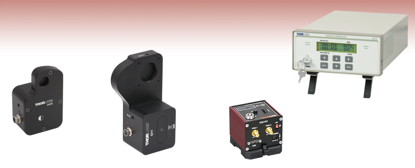
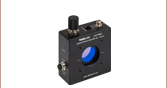
- Ø1/2" Aperture
- Close Activation Time: 4.08 ms
- SM05-Threaded (0.535"-40) Aperture for SM05 Lens Tube Compatibility
- Default Position: Closed
- Compatible with the SC10 and KSC101 Controllers (Sold Separately Below)
The SH05(/M) optical beam shutter has a Ø1/2" aperture with a single blade that slides across the aperture. This shutter has a close activation time of ≤4.08 ms when used with the SC10 or KSC101 controller. A graph that shows the open and close times of the optical shutter driven with the KSC101 controller is shown to the right. Please see the Specs tab for additional specifications.
Both sides of this shutter's aperture are internally SM05 (0.535"-40) threaded for compatablity with our SM05 Lens Tubes. For post mounting, the SH05(/M) has three 8-32 (M4) tapped holes.
For applications requiring blades that open from the center, we offer a Ø1/2" diaphragm shutter and controller with five stainless steel blades.

 Zoom
Zoom
Click to Enlarge The SH1 is compatible with SM1 Lens Tubes and 30 mm Cage Systems.
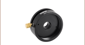
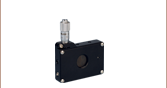
- Ø1" Aperture
- Close Activation Time: <10 ms
- SM1-Threaded (1.035"-40) Aperture for SM1 Lens Tube Compatibility
- Default Position: Closed
- Compatible with the SC10 Controller (Sold Separately Below)
The SH1(/M) optical beam shutter has a Ø1" aperture with a single blade that slides across the aperture. This shutter has a close activation of <10 ms when used with the SC10 Shutter Controller (sold separately below). Please note that this optical shutter is not compatible with the KSC101 controller; it can be used with third-party controllers. See the Specs tab for specifications.
Both sides of the aperture are internally SM1 (1.035"-40) threaded for compatibility with our SM1 Lens Tubes. The SH1(/M) has three 8-32 (M4) tapped holes for post mounting and 4-40 taps for use with our 30 mm Cage Components.
For applications requiring blades that open from the center, we offer a Ø1" diaphragm shutter and controller with five stainless steel blades.

 Zoom
Zoom- Local Operation or Remote Control via LabVIEW, LabWindows, RS-232, or BNC
- Programmable with Repeating Open/Close Sequences at Millisecond Intervals
- LCD Front Panel with Dedicated Shutter Status Indicators
- Safety Alarm When Coupled with SH05 and SH1 Beam Shutter
- Key Switch Provides Additional Safety
Thorlabs' SC10 Shutter Controller provides an easy-to-use control interface for our SH05 and SH1 Optical Shutters. The shutter can be controlled by hand using the buttons on the front of the unit, and the back includes a BNC input for external triggering, a BNC output for synchronization with other equipment, and an RS-232 port for remote computer control. Dedicated lights on the front panel reveal if the shutter is enabled and if the shutter is open. It also features a keyswitch that enables opening of the shutter, helping to comply with lab laser safety requirements. In addition, it incorporates a safety interlock that overrides all system commands and closes the shutter. If the interlock is tripped, the keyswitch must be cycled to resume operations.
The easy-to-read LCD front panel provides access to the same commands as the included LabVIEW and LabWindows software packages. In addition to simply opening or closing the shutter, a repeating sequence of open and close events with exposure times as low as 10 ms can be set up and initiated either by a front panel button, a TTL pulse (+5 V), or a computer command via RS-232. Alternatively, the shutter can be synchronized to follow the rising and falling edges of an external voltage supplied over BNC.
The optical shutter controller includes LabVIEW VI's suitable for integrating into existing LabVIEW applications. A standalone executable written in LabWindows/CVI is also provided, allowing remote computer control of the SC10 without any additional programming. See the SC10 Software tab to download these packages.
The shutter controller's BNC output allows it to double as a standalone digital delay generator with 1 ms resolution and 0.1 ms accuracy.
In October 2012, the firmware of the SC10 was updated to address compatibility issues with our SH1 Shutter. For units purchased prior to that date, a free firmware update is available; please see the SC10 Software tab for details.

 Zoom
Zoom
Click to Enlarge
Back and Top Views of the KSC101 K-Cube
(See the Pin Diagrams Tab for More Information)

Click to Enlarge KCH301 USB Controller Hub (Sold Separately) with Installed K-Cube and T-Cube™ Modules (T-Cubes Require the KAP101 Adapter)
- Local Operation or Remote Control via USB or SMA
- Full Kinesis® or APT™ Software Control Suite (See Motion Control Software Tab for Details)
- Programmable with Repeating Open/Close Sequences at Millisecond Intervals
- Manual Controls and Digital Display Allow for Mode Selection and On/Off Time Control
- Laser Safety Interlock Jack and Safety Enable Key Switch
- Single-Channel Power Supply Unit Sold Separately
- Multi-Unit Operation Using USB Controller Hubs (Sold Separately)
Thorlabs' KSC101 K-Cube™ Optical Shutter Controller is a compact, 60.0 mm x 60.0 mm x 49.2 mm controller that is designed for use with our SH05(/M) Shutter. The controller features an embedded digital signal processor (DSP) to provide a multitude of flexible operating modes; see the Specs tab for details. Embedded software functionality allows this unit to control solenoid devices using the on-unit menu button, display, and control wheel; using DSP timed operations; or using external trigger signals for operation with third-party equipment. The trigger out connection, defaulted on Trigger 2, allows multiple K-Cube controllers to be connected together for synchronized multi-channel system operation.
The KSC101 is also equipped with built-in safety interlock functionality in the form of a 3.5 mm stereo jack. A shorted connector is included for overriding this connection, while a custom circuit may be created for lab safety applications using the included 3.5 mm stereo connector. The circuit must be closed for the controller to be able to open the shutter. To comply with laser safety requirements, the controller also features a key switch that enables or disables opening of the shutter.
The easy-to-read digital display provides access to the same commands as the included Kinesis® software package. In addition to simply opening or closing the shutter, a repeating sequence of open and close events with exposure times as low as 15 ms can be set up and initiated either by the top panel controls, a TTL pulse (+5 V), or a computer command via USB 3.0.
USB connectivity provides easy 'Plug-and-Play' PC-controlled operation with two available software platforms: our new Kinesis software package or our legacy APT (Advanced Positioning Technology) software package. For more details on both software packages, please see the Motion Control Software tab. For convenience, a 1.5 m long Type A to Type Micro B USB 3.0 cable is included with the KSC101 cube.
Power Supply Options
The preferred power supply (single channel or hub-based) depends on the end user's application and whether you already own compatible power supplies. To that end and in keeping with Thorlabs' green initiative, we do not ship these units bundled with a power supply.
Multiple units can be connected to a single PC by using the KCH301 or KCH601 USB Controller Hubs, available below, for multi-axis motion control applications. The KCH301, shown in the image above, allows up to three T- or K-Cube controllers to be used while the KCH601 allows up to six controllers to be used.
All power supply options compatible with the KSC101 Controller can be found below. For more information on the KSC101, please see the full web presentation.