 Products Home / Optical Fiber & Fiber Patch Cables / Single Mode Fiber Optic Patch Cables / Low-Insertion-Loss Single Mode Patch Cables
Low-Insertion-Loss Single Mode Patch Cables

- Typical Insertion Loss: 0.3 dB to 0.9 dB (Wavelength Specific)
- SM Patch Cables for 320 - 430 nm, 405 - 532 nm, 488 - 633 nm, and 633 - 780 nm
- Available with FC/PC, FC/APC, or FC/PC to FC/APC Connectors
P3-405P-FC-5
FC/APC Connectors
P1-305P-FC-2
FC/PC Connectors
P5-405P-PCAPC-1
FC/PC Connector
FC/APC Connector


Please Wait
| Stock Single Mode Patch Cables Selection Guide | |
|---|---|
| Standard Cables | FC/PC to FC/PC |
| FC/APC to FC/APC | |
| Hybrid | |
| AR-Coated Patch Cables | |
| HR-Coated Patch Cables | |
| Beamsplitter-Coated Patch Cables | |
| Low-Insertion-Loss Patch Cables | |
| MIR Fluoride Fiber Patch Cables | |


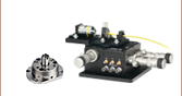
Results from our Centroc test equipment, showing the typical core angular alignment and concentricity for a standard patch cable (left) and a low insertion loss cable (right).
Features
- Low Insertion Loss (Typical):
- 0.3 dB (633 - 780 nm)
- 0.5 - 0.6 dB (405 - 532 nm and 488 nm - 633 nm)
- 0.9 dB (320 - 430 nm)
- Available Wavelength Ranges: 320 - 430 nm, 405 - 532 nm, 488 - 633 nm, or 633 - 780 nm
- Connector Options Available (All 2.0 mm Narrow Key):
- FC/PC
- FC/APC
- FC/PC to FC/APC
- Individual Test Data Included with Each Cable
- Two CAPF Dust Caps Included
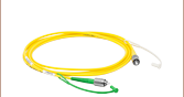
Thorlabs offers low-insertion-loss, single mode patch cables with FC/PC or FC/APC connectors on both ends. Additionally, we offer an FC/PC to FC/APC cable option. These small-core patch cables are manufactured in our facility on state-of-the-art equipment and individually handpicked to ensure tightly toleranced fiber and matched ferrules. They are tested to ensure exceptionally low insertion loss when used with other low-insertion-loss cables.
The cables offered here use fibers designed for signal transmission in the 320 - 430 nm, 400 - 532 nm, 488 - 633 nm, or 633 - 780 nm range and boast a typical insertion loss of 0.9 dB, 0.5-0.6 dB, or 0.3 dB, respectively, between two low-insertion-loss cables. Our cables offer high return loss of 50 dB (typical) for FC/PC cables and 60 dB (typical) for FC/APC cables. Each fiber patch cable's measured performance characteristics are reported on the included specification sheet.
In standard cables, there can be slight variances in fiber parameters (e.g., core-to-cladding eccentricity or misalignment of the core from the cable center). The small core size of SM cables exacerbates these fiber-to-fiber variances when trying to align the cores of two fibers using standard mating sleeves, ultimately resulting in higher insertion loss. Through an extensive selection and testing procedure, our low-insertion-loss patch cables offer well-centered cores with high concentricity, greatly reducing the insertion loss of the cable (see the Comparison tab for more details).
The process of producing low-insertion-loss patch cables starts with hand selecting fiber with better than typical core-to-cladding concentricity as well as a tight tolerance on the fiber outer diameter for ferrule matching. Each ferrule is also hand selected to match the ferrule inner diameter to the fiber size as well as the ferrule bore to the outer diameter concentricity. These selections ensure the tightest fit for the fiber and best concentricity for low-insertion-loss performance. The ferrule is machine polished, and the fiber core is aligned to within ±5 degrees of the connector key. Finally, the patch cable's insertion loss is tested using a low insertion loss master cable. By hand selecting fiber and ferrules, Thorlabs is able to offer low-insertion-loss cables that provide superior performance and quality.
Mating sleeves are available to connect FC to FC, SMA to SMA, and FC to SMA connectors. These mating sleeves minimize back reflections and ensure proper alignment of the cores of each connectorized fiber end. We especially recommend using our ADAFCPM2 precision PM mating sleeve, which is manufactured to tighter tolerances, and was used to achieve the insertion loss specifications quoted below.

Each patch cable includes two protective caps that shield the ferrule ends from dust and other contaminants. Additional CAPF Plastic Fiber Caps and CAPFM Metal Threaded Fiber Caps are sold separately.
If you cannot find the appropriate stock patch cable for your application, Thorlabs offers custom low-insertion-loss patch cables. Please contact Tech Support for a quote. Additionally, standard custom patch cables with same-day shipping can be ordered by clicking on the box below.
| Item # Prefix | P1-305P-FC | P3-305P-FC | P5-305P-FCAPC | P1-405P-FC | P3-405P-FC | P5-405P-FCAPC |
|---|---|---|---|---|---|---|
| Connector Type | FC/PC | FC/APC | FC/PC to FC/APC | FC/PC | FC/APC | FC/PC to FC/APC |
| Fiber Type | SM300 | SM400 | ||||
| Operating Wavelength | 320 - 430 nm | 405 - 532 nm | ||||
| Cutoff Wavelength | ≤310 nm | 305 - 400 nm | ||||
| Insertion Loss (Max/Typ.)a | 1.5 dB / 0.9 dB | 1.0 dB / 0.5 dB (1 m and 2 m Long Cables) 1.0 dB / 0.6 dB (5 m Long Cables) |
||||
| Mode Field Diameter | 2.0 - 2.4 µm @ 350 nm | 2.5 - 3.4 µm @ 480 nm | ||||
| Key Width | 2.0 mm (Narrow) | |||||
| Cable Length Tolerance | +0.075/-0.0 m | |||||
| Jacket Type | Ø3 mm Yellow PVC Furcation Tubing | |||||
| Cladding Diameter | 125 ± 1.0 µm | |||||
| Coating Diameter | 245 ± 15 µm | |||||
| Numerical Aperture | 0.12 - 0.14 | |||||
| Max Attenuationb | ≤70 dB/km @ 350 nm | ≤50 dB/km @ 430 nm ≤30 dB/km @ 532 nm |
||||
| Operating Temperature | 0 to 70 °C | |||||
| Storage Temperature | -45 to 85 °C | |||||
| Item # Prefix | P1-460P-FC | P3-460P-FC | P5-460P-FCAPC | P1-630P-FC | P3-630P-FC | P5-630P-PCAPC |
|---|---|---|---|---|---|---|
| Connector Type | FC/PC | FC/APC | FC/PC to FC/APC | FC/PC | FC/APC | FC/PC to FC/APC |
| Fiber Type | SM450 | SM600 | ||||
| Operating Wavelength | 488 - 633 nma | 633 - 780 nm | ||||
| Cutoff Wavelength | 350 - 470 nma | 500 - 600 nm | ||||
| Insertion Loss (Max/Typ.)b | 1.0 dB / 0.5 dB (1 m and 2 m Long Cables) 1.0 dB / 0.6 dB (5 m Long Cables) |
0.8 dB / 0.3 dB | ||||
| Mode Field Diameter | 2.8 - 4.1 µm @ 488 nm | 3.6 - 5.3 µm @ 633 nm | ||||
| Key Width | 2.0 mm (Narrow) | |||||
| Cable Length Tolerance | +0.075/-0.0 m | |||||
| Jacket Type | Ø3 mm Yellow PVC Furcation Tubing | |||||
| Cladding Diameter | 125 ± 1.0 µm | |||||
| Coating Diameter | 245 ± 15 µm | |||||
| Numerical Aperture | 0.10 - 0.14 | |||||
| Max Attenuationc | ≤50 dB/km @ 488 nm | ≤15 dB/km @ 630 nmd | ||||
| Operating Temperature | 0 to 70 °C | |||||
| Storage Temperature | -45 to 85 °C | |||||
405 nm Cable Comparison


The graphs above depict sample data comparing Thorlabs' 405 nm, Low-Insertion-Loss (LIL) Cables and our Standard 405 nm Cables for 1 m, 2 m, and 5 m cable lengths. The results show that the LIL cables have an average insertion loss of -0.37 dB for 1 m cables, -0.39 for 2 m cables, and -0.59 dB for 5 m cables, whereas the standard cables demonstrate an insertion loss of -2.48 dB for 1 m cables, -2.44 dB for 2 m cables, and -2.42 dB for 5 m cables. The measured insertion losses for 5 m cables are slightly higher since we did not correct for the attenuation of the fiber. The insertion loss of our 405 nm LIL cables is, on average, ~7 times better compared to that of our standard cables.
To test the insertion loss for our 405 nm cables, a 405 nm fiber-coupled laser source was coupled to a low-insertion-loss master cable; the output power from the cable was measured and adjusted for consistency. Each tested fiber was inspected, cleaned, and connected to a ADAFCPM2 mating sleeve, and the output power from the cable was recorded. In this way, consistent measurement of each fiber's insertion loss can be measured and compared to the insertion loss of other cables. The test procedure is shown in the diagram to the right.
| Quick Links |
|---|
| Damage at the Air / Glass Interface |
| Intrinsic Damage Threshold |
| Preparation and Handling of Optical Fibers |
Laser-Induced Damage in Silica Optical Fibers
The following tutorial details damage mechanisms relevant to unterminated (bare) fiber, terminated optical fiber, and other fiber components from laser light sources. These mechanisms include damage that occurs at the air / glass interface (when free-space coupling or when using connectors) and in the optical fiber itself. A fiber component, such as a bare fiber, patch cable, or fused coupler, may have multiple potential avenues for damage (e.g., connectors, fiber end faces, and the device itself). The maximum power that a fiber can handle will always be limited by the lowest limit of any of these damage mechanisms.
While the damage threshold can be estimated using scaling relations and general rules, absolute damage thresholds in optical fibers are very application dependent and user specific. Users can use this guide to estimate a safe power level that minimizes the risk of damage. Following all appropriate preparation and handling guidelines, users should be able to operate a fiber component up to the specified maximum power level; if no maximum is specified for a component, users should abide by the "practical safe level" described below for safe operation of the component. Factors that can reduce power handling and cause damage to a fiber component include, but are not limited to, misalignment during fiber coupling, contamination of the fiber end face, or imperfections in the fiber itself. For further discussion about an optical fiber’s power handling abilities for a specific application, please contact Thorlabs’ Tech Support.

Click to Enlarge
Undamaged Fiber End

Click to Enlarge
Damaged Fiber End
Damage at the Air / Glass Interface
There are several potential damage mechanisms that can occur at the air / glass interface. Light is incident on this interface when free-space coupling or when two fibers are mated using optical connectors. High-intensity light can damage the end face leading to reduced power handling and permanent damage to the fiber. For fibers terminated with optical connectors where the connectors are fixed to the fiber ends using epoxy, the heat generated by high-intensity light can burn the epoxy and leave residues on the fiber facet directly in the beam path.
| Estimated Optical Power Densities on Air / Glass Interfacea | ||
|---|---|---|
| Type | Theoretical Damage Thresholdb | Practical Safe Levelc |
| CW (Average Power) |
~1 MW/cm2 | ~250 kW/cm2 |
| 10 ns Pulsed (Peak Power) |
~5 GW/cm2 | ~1 GW/cm2 |
Damage Mechanisms on the Bare Fiber End Face
Damage mechanisms on a fiber end face can be modeled similarly to bulk optics, and industry-standard damage thresholds for UV Fused Silica substrates can be applied to silica-based fiber. However, unlike bulk optics, the relevant surface areas and beam diameters involved at the air / glass interface of an optical fiber are very small, particularly for coupling into single mode (SM) fiber. therefore, for a given power density, the power incident on the fiber needs to be lower for a smaller beam diameter.
The table to the right lists two thresholds for optical power densities: a theoretical damage threshold and a "practical safe level". In general, the theoretical damage threshold represents the estimated maximum power density that can be incident on the fiber end face without risking damage with very good fiber end face and coupling conditions. The "practical safe level" power density represents minimal risk of fiber damage. Operating a fiber or component beyond the practical safe level is possible, but users must follow the appropriate handling instructions and verify performance at low powers prior to use.
Calculating the Effective Area for Single Mode and Multimode Fibers
The effective area for single mode (SM) fiber is defined by the mode field diameter (MFD), which is the cross-sectional area through which light propagates in the fiber; this area includes the fiber core and also a portion of the cladding. To achieve good efficiency when coupling into a single mode fiber, the diameter of the input beam must match the MFD of the fiber.
As an example, SM400 single mode fiber has a mode field diameter (MFD) of ~Ø3 µm operating at 400 nm, while the MFD for SMF-28 Ultra single mode fiber operating at 1550 nm is Ø10.5 µm. The effective area for these fibers can be calculated as follows:
SM400 Fiber: Area = Pi x (MFD/2)2 = Pi x (1.5 µm)2 = 7.07 µm2 = 7.07 x 10⁻⁸ cm2
SMF-28 Ultra Fiber: Area = Pi x (MFD/2)2 = Pi x (5.25 µm)2 = 86.6 µm2 = 8.66 x 10⁻⁷ cm2
To estimate the power level that a fiber facet can handle, the power density is multiplied by the effective area. Please note that this calculation assumes a uniform intensity profile, but most laser beams exhibit a Gaussian-like shape within single mode fiber, resulting in a higher power density at the center of the beam compared to the edges. Therefore, these calculations will slightly overestimate the power corresponding to the damage threshold or the practical safe level. Using the estimated power densities assuming a CW light source, we can determine the corresponding power levels as:
SM400 Fiber: 7.07 x 10⁻⁸ cm2 x 1 MW/cm2 = 7.1 x 10⁻⁸ MW = 71 mW (Theoretical Damage Threshold)
7.07 x 10⁻⁸ cm2 x 250 kW/cm2 = 1.8 x 10⁻⁵ kW = 18 mW (Practical Safe Level)
SMF-28 Ultra Fiber: 8.66 x 10⁻⁷ cm2 x 1 MW/cm2 = 8.7 x 10⁻⁷ MW = 870 mW (Theoretical Damage Threshold)
8.66 x 10⁻⁷ cm2 x 250 kW/cm2 = 2.1 x 10⁻⁴ kW = 210 mW (Practical Safe Level)
The effective area of a multimode (MM) fiber is defined by the core diameter, which is typically far larger than the MFD of an SM fiber. For optimal coupling, Thorlabs recommends focusing a beam to a spot roughly 70 - 80% of the core diameter. The larger effective area of MM fibers lowers the power density on the fiber end face, allowing higher optical powers (typically on the order of kilowatts) to be coupled into multimode fiber without damage.
Damage Mechanisms Related to Ferrule / Connector Termination

Click to Enlarge
Plot showing approximate input power that can be incident on a single mode silica optical fiber with a termination. Each line shows the estimated power level due to a specific damage mechanism. The maximum power handling is limited by the lowest power level from all relevant damage mechanisms (indicated by a solid line).
Fibers terminated with optical connectors have additional power handling considerations. Fiber is typically terminated using epoxy to bond the fiber to a ceramic or steel ferrule. When light is coupled into the fiber through a connector, light that does not enter the core and propagate down the fiber is scattered into the outer layers of the fiber, into the ferrule, and the epoxy used to hold the fiber in the ferrule. If the light is intense enough, it can burn the epoxy, causing it to vaporize and deposit a residue on the face of the connector. This results in localized absorption sites on the fiber end face that reduce coupling efficiency and increase scattering, causing further damage.
For several reasons, epoxy-related damage is dependent on the wavelength. In general, light scatters more strongly at short wavelengths than at longer wavelengths. Misalignment when coupling is also more likely due to the small MFD of short-wavelength SM fiber that also produces more scattered light.
To minimize the risk of burning the epoxy, fiber connectors can be constructed to have an epoxy-free air gap between the optical fiber and ferrule near the fiber end face. Our high-power multimode fiber patch cables use connectors with this design feature.
Determining Power Handling with Multiple Damage Mechanisms
When fiber cables or components have multiple avenues for damage (e.g., fiber patch cables), the maximum power handling is always limited by the lowest damage threshold that is relevant to the fiber component. In general, this represents the highest input power that can be incident on the patch cable end face and not the coupled output power.
As an illustrative example, the graph to the right shows an estimate of the power handling limitations of a single mode fiber patch cable due to damage to the fiber end face and damage via an optical connector. The total input power handling of a terminated fiber at a given wavelength is limited by the lower of the two limitations at any given wavelength (indicated by the solid lines). A single mode fiber operating at around 488 nm is primarily limited by damage to the fiber end face (blue solid line), but fibers operating at 1550 nm are limited by damage to the optical connector (red solid line).
In the case of a multimode fiber, the effective mode area is defined by the core diameter, which is larger than the effective mode area for SM fiber. This results in a lower power density on the fiber end face and allows higher optical powers (on the order of kilowatts) to be coupled into the fiber without damage (not shown in graph). However, the damage limit of the ferrule / connector termination remains unchanged and as a result, the maximum power handling for a multimode fiber is limited by the ferrule and connector termination.
Please note that these are rough estimates of power levels where damage is very unlikely with proper handling and alignment procedures. It is worth noting that optical fibers are frequently used at power levels above those described here. However, these applications typically require expert users and testing at lower powers first to minimize risk of damage. Even still, optical fiber components should be considered a consumable lab supply if used at high power levels.
Intrinsic Damage Threshold
In addition to damage mechanisms at the air / glass interface, optical fibers also display power handling limitations due to damage mechanisms within the optical fiber itself. These limitations will affect all fiber components as they are intrinsic to the fiber itself. Two categories of damage within the fiber are damage from bend losses and damage from photodarkening.
Bend Losses
Bend losses occur when a fiber is bent to a point where light traveling in the core is incident on the core/cladding interface at an angle higher than the critical angle, making total internal reflection impossible. Under these circumstances, light escapes the fiber, often in a localized area. The light escaping the fiber typically has a high power density, which burns the fiber coating as well as any surrounding furcation tubing.
A special category of optical fiber, called double-clad fiber, can reduce the risk of bend-loss damage by allowing the fiber’s cladding (2nd layer) to also function as a waveguide in addition to the core. By making the critical angle of the cladding/coating interface higher than the critical angle of the core/clad interface, light that escapes the core is loosely confined within the cladding. It will then leak out over a distance of centimeters or meters instead of at one localized spot within the fiber, minimizing the risk of damage. Thorlabs manufactures and sells 0.22 NA double-clad multimode fiber, which boasts very high, megawatt range power handling.
Photodarkening
A second damage mechanism, called photodarkening or solarization, can occur in fibers used with ultraviolet or short-wavelength visible light, particularly those with germanium-doped cores. Fibers used at these wavelengths will experience increased attenuation over time. The mechanism that causes photodarkening is largely unknown, but several fiber designs have been developed to mitigate it. For example, fibers with a very low hydroxyl ion (OH) content have been found to resist photodarkening and using other dopants, such as fluorine, can also reduce photodarkening.
Even with the above strategies in place, all fibers eventually experience photodarkening when used with UV or short-wavelength light, and thus, fibers used at these wavelengths should be considered consumables.
Preparation and Handling of Optical Fibers
General Cleaning and Operation Guidelines
These general cleaning and operation guidelines are recommended for all fiber optic products. Users should still follow specific guidelines for an individual product as outlined in the support documentation or manual. Damage threshold calculations only apply when all appropriate cleaning and handling procedures are followed.
-
All light sources should be turned off prior to installing or integrating optical fibers (terminated or bare). This ensures that focused beams of light are not incident on fragile parts of the connector or fiber, which can possibly cause damage.
-
The power-handling capability of an optical fiber is directly linked to the quality of the fiber/connector end face. Always inspect the fiber end prior to connecting the fiber to an optical system. The fiber end face should be clean and clear of dirt and other contaminants that can cause scattering of coupled light. Bare fiber should be cleaved prior to use and users should inspect the fiber end to ensure a good quality cleave is achieved.
-
If an optical fiber is to be spliced into the optical system, users should first verify that the splice is of good quality at a low optical power prior to high-power use. Poor splice quality may increase light scattering at the splice interface, which can be a source of fiber damage.
-
Users should use low power when aligning the system and optimizing coupling; this minimizes exposure of other parts of the fiber (other than the core) to light. Damage from scattered light can occur if a high power beam is focused on the cladding, coating, or connector.
Tips for Using Fiber at Higher Optical Power
Optical fibers and fiber components should generally be operated within safe power level limits, but under ideal conditions (very good optical alignment and very clean optical end faces), the power handling of a fiber component may be increased. Users must verify the performance and stability of a fiber component within their system prior to increasing input or output power and follow all necessary safety and operation instructions. The tips below are useful suggestions when considering increasing optical power in an optical fiber or component.
-
Splicing a fiber component into a system using a fiber splicer can increase power handling as it minimizes possibility of air/fiber interface damage. Users should follow all appropriate guidelines to prepare and make a high-quality fiber splice. Poor splices can lead to scattering or regions of highly localized heat at the splice interface that can damage the fiber.
-
After connecting the fiber or component, the system should be tested and aligned using a light source at low power. The system power can be ramped up slowly to the desired output power while periodically verifying all components are properly aligned and that coupling efficiency is not changing with respect to optical launch power.
-
Bend losses that result from sharply bending a fiber can cause light to leak from the fiber in the stressed area. When operating at high power, the localized heating that can occur when a large amount of light escapes a small localized area (the stressed region) can damage the fiber. Avoid disturbing or accidently bending fibers during operation to minimize bend losses.
-
Users should always choose the appropriate optical fiber for a given application. For example, large-mode-area fibers are a good alternative to standard single mode fibers in high-power applications as they provide good beam quality with a larger MFD, decreasing the power density on the air/fiber interface.
-
Step-index silica single mode fibers are normally not used for ultraviolet light or high-peak-power pulsed applications due to the high spatial power densities associated with these applications.
| Posted Comments: | |
loic.morvan
(posted 2018-12-07 13:19:25.703) Hello,
would it be possible to get such low-loss connectors with PM fiber ?
Our specific interest : PM780-HP fiber, in FC/APC geometry.
Best regards,
Loïc YLohia
(posted 2018-12-07 09:45:15.0) Hello Loïc, thank you for contacting Thorlabs. Custom items can be quoted by emailing your local Thorlabs Tech Support office (in this case techsupport.fr@thorlabs.com). I have reached out to you directly with more details about your inquiry. ywcho
(posted 2018-09-28 02:01:22.763) Hello.
Is 780-HP patch cable also available for the low-insertion-loss option?
Thanks. nbayconich
(posted 2018-10-01 10:45:09.0) Thank you for contacting Thorlabs. We can provide this as a custom option, I will reach out to you directly to discuss our custom capabilities. zeuner
(posted 2017-05-09 14:17:50.513) Dear Thorlabs Team,
Is it possible to buy this high concentricity fibers also for the 780HP type or is it possible to get such fibers on custom request?
Cheers,
Katharina tfrisch
(posted 2017-05-17 03:07:57.0) Hello, thank you for contacting Thorlabs. I will reach out to you directly to discuss a quote. art.nitkowski
(posted 2013-07-02 11:12:27.367) Do you have any plans on releasing a low insertion loss fiber that covers the 800-900 nm wavelength range, such as a low loss equivalent to your 780-hp fiber? We find that these fiber connectors also suffer from large insertion losses and a low loss version would be very useful in optical coherence tomography systems. pbui
(posted 2013-07-03 16:52:00.0) Response from Phong at Thorlabs: Thank you for your feedback. I will discuss the possibility of offering low IL patch cables for the 800-900 nm range with our Fiber Group. I will contact you directly to discuss your requirements in the context of your application. |