 Products Home / Motion Control Electronics / DC Servo Controllers / Benchtop Brushless DC Motor Controllers
Benchtop Brushless DC Motor Controllers
- One-, Two-, and Three-Channel Models Available
- Supports 3-Phase, Brushless, DC Servo Motors
with up to 5 A Peak Coil Current - Encoder Feedback
- APT™ Control Software Suite
BBD203
3-Channel Controller
BBD201
1-Channel Controller
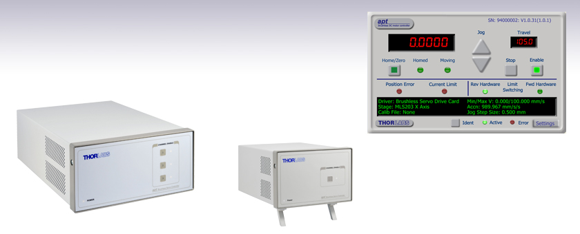
GUI Panel


Please Wait
| Benchtop Motion Controllers |
|---|
| 1-, 2- and 3-Channel Brushless DC Servo Controllers |
| 1-, 2-, and 3-Channel Stepper Motor Controllers |
| 1- and 3-Channel Open Loop Piezo Controllers |
| 1- and 3-Channel Closed Loop Piezo Controllers |
| 2-Channel NanoTrak® Auto-Alignment Controller |
| Other Brushless DC Servo Controllers | |
|---|---|
| K-Cube™ Single-Channel Controller | |

Click to Enlarge
BBD202 Rear Panel

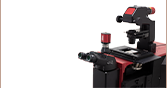
The image above shows a typical system, comprising of the BBD202 brushless DC motor controller, an MJC001 joystick console, and an MLS203 XY stage mounted to an Olympus XI71 microscope.
Features
- Supports Thorlabs' Range of 3-Phase, Brushless DC Servo Motor Products
- Encoder Feedback for Closed-Loop Velocity and Position Control
- USER I/O Port Exposes Encoder Signals for Monitoring
- AUX I/O Port Exposes Digital Input and Output Signals
- Fully Supported by the APT™ Software Control Suite
- USB Plug-and-Play
- Seamless Integration with All APT™ Family Controllers
- ActiveX® Software Graphical Panels
The BBD Series of Brushless DC Motor Controllers are ideal for motion control applications demanding operation at high speeds (hundreds of mm/s) and with high encoder resolution (<100 nm). These controllers offer up to three channels of high-precision motion control for a wide range of applications, particularly microscopy sample manipulation if paired with our MLS203 Series of Dual-Axis Scanning Stages. With the latest digital and analog techniques and high-bandwidth, high-power servo control circuitry, these controllers have been designed to drive Thorlabs' range of rotary and linear 3-phase, brushless DC servo motor products.
Integrated into the APT family of products, these controllers offer Thorlabs' standard control and programming interface, allowing for easy integration into automated motion control applications. These units are capable of being reprogrammed in-field, allowing the option of upgrading the units with future firmware releases as soon as new programming interfaces (such as microscopy standard command sets) are added.
USB connectivity provides easy plug-and-play PC operation. Multiple units can be connected to a single PC via standard USB hub technology for multi-axis motion control applications. Coupling this with the user friendly APT™ software allows the user to get reasonably complex move sequences up and running in a short space of time. For example, all relevant operating parameters are set automatically for Thorlabs stage and actuator products. Advanced custom motion control applications and sequences are also possible using the extensive ActiveX® programming environment described in more detail on the Motion Control Software tab. These ActiveX Controls can be incorporated into a wide range of software development environments including Labview, C++, and Matlab.
We have ensured that the software interfaces to the BBD series are highly integrated with all other APT™ family controllers, providing easy system integration and reduced learning curve. As one of the newest members of the APT™ family of controllers, these units are backed up by the fully featured APT™ suite of PC software tools for immediate and easy out-of-the-box configuration and usage.
Note: The BBD20x series controllers is specifically designed for benchtop use. For a 19" rack application, please use our RBD201 controller.
Not For Use with Brushed DC Motors
This controller is designed for use with high power, brushless DC servo motors. For control of the Thorlabs brushed DC servo motor devices, please see the KDC101 DC Servo Motor Driver K-Cube.
Optional Joystick Console
The MJC001 joystick console has been designed for microscope users, to provide intuitive, tactile, manual positioning of the stage. The console features a two axis joystick for XY control. In most applications, the default parameter settings saved within the controller allow the joystick to be used out-of-the-box, with no need for further setup, thereby negating the requirement to be connected to a host PC, and allowing true remote operation.
| Item # | BBD201 | BBD202 | BBD203 |
|---|---|---|---|
| Number of Channels | 1 | 2 | 3 |
| Drive Connector | 8 Pin DIN, Round, Female | ||
| Feedback Connector | 15-Pin D-Type | ||
| Brushless Continuous Output | 2.5 A | 5 A | 5 A |
| PWM Frequency | 40 kHz | ||
| Operating Modes | Position and Velocity | ||
| Control Algorithm | 16-Bit Digital PID Servo Loop with Velocity and Acceleration Feedforward | ||
| Velocity Profile | Trapezoidal/S-Curve | ||
| Position Count | 32 Bit | ||
| Position Feedback | Incremental Encoder | ||
| Encoder Bandwidth | 2.5 MHz (10 M Counts/sec) | ||
| Encoder Supply | 5 V | ||
| AUX Control Connector | 15-Pin D-Type | ||
| External System Communications | Type B USB, Female | ||
| Input Power Requirements | 250 VA Volt: 100 to 240 VAC Freq: 47 to 63 Hz Fuse: 3.15 A |
||
| Dimensions | 174 mm x 245 mm x 126 mm (6.85" x 9.65" x 4.96") |
240 mm x 337.9 mm x 124.8 mm (9.5" x 13.3" x 4.9") |
|
| Weight | 3.46 kg (7.6 lb) | 6.1 kg (13.42 lb) | |
MOTOR DRIVE
Female

| Pin | Description | Pin | Description |
|---|---|---|---|
| 1 | Motor Phase V | 5 | Stage ID |
| 2 | GND | 6 | GND |
| 3 | Temp Sensor (Not Used) | 7 | Motor Phase W |
| 4 | Motor Phase U | 8 | Enable |
FEEDBACK
D-type Female

| Pin | Description | Pin | Description |
|---|---|---|---|
| 1 | Not Connected | 9 | GND |
| 2 | GND | 10 | Limit Switch + |
| 3 | Not Connected | 11 | Limit Switch - |
| 4 | Index - | 12 | Index + |
| 5 | QB - | 13 | QB + |
| 6 | QA - | 14 | QA + |
| 7a | 5 V | 15 | Not Connected |
| 8a | 5 V |
USER I/O
D-type Male

| Pin | Description | Pin | Description |
|---|---|---|---|
| 1 | 5 V | 9 | QA + |
| 2 | Trigger IN | 10 | QA - |
| 3 | Trigger OUT | 11 | QB+ |
| 4 | Ground | 12 | QB - |
| 5 | Ground | 13 | Index/Ref + |
| 6 | For Future Use | 14 | Index/Ref - |
| 7 | For Future Use | 15 | Ground |
| 8 | For Future Use |
AUX I/O
D-type Female
| Pin | Description | Pin | Description |
|---|---|---|---|
| 1 | Digital O/P 1 | 9 | Digital Ground |
| 2 | Digital O/P 2 | 10 | Digital Ground |
| 3 | Digital O/P 3 | 11 | For Future Use |
| 4 | Digital O/P 4 | 12 | For Future Use |
| 5 | Digital Ground | 13 | Digital I/P 4 |
| 6 | Digital I/P 1 | 14 | 5 V Supply O/P |
| 7 | Digital I/P 2 | 15 | 5 V Supply O/P |
| 8 | Digital I/P 3 |
HANDSET
Mini DIN Female

| Pin | Description | Pin | Description |
|---|---|---|---|
| 1 | RX (controller intput)/RS232 | 4 | Supply Voltage for Handset 5V |
| 2 | Ground | 5 | TX (controller output)/RS232 |
| 3 | Ground | 6 | Ground |
INTERCONNECT
D-type Male

| Pin | Description | Pin | >Description |
|---|---|---|---|
| 1 | Not Connected | 6 | Not Connected |
| 2 | RX (controller input) | 7 | Not Connected |
| 3 | TX (controller output) | 8 | Not Connected |
| 4 | Not Connected | 9 | Not Connected |
| 5 | Ground |
USB
Type B USB Female

Thorlabs offers two platforms to drive our wide range of motion controllers: our Kinesis® software package or the legacy APT™ (Advanced Positioning Technology) software package. Either package can be used to control devices in the Kinesis family, which covers a wide range of motion controllers ranging from small, low-powered, single-channel drivers (such as the K-Cubes™ and T-Cubes™) to high-power, multi-channel, modular 19" rack nanopositioning systems (the APT Rack System).
The Kinesis Software features .NET controls which can be used by 3rd party developers working in the latest C#, Visual Basic, LabVIEW™, or any .NET compatible languages to create custom applications. Low-level DLL libraries are included for applications not expected to use the .NET framework. A Central Sequence Manager supports integration and synchronization of all Thorlabs motion control hardware.

Kinesis GUI Screen

APT GUI Screen
Our legacy APT System Software platform offers ActiveX-based controls which can be used by 3rd party developers working on C#, Visual Basic, LabVIEW™, or any Active-X compatible languages to create custom applications and includes a simulator mode to assist in developing custom applications without requiring hardware.
By providing these common software platforms, Thorlabs has ensured that users can easily mix and match any of the Kinesis and APT controllers in a single application, while only having to learn a single set of software tools. In this way, it is perfectly feasible to combine any of the controllers from single-axis to multi-axis systems and control all from a single, PC-based unified software interface.
The software packages allow two methods of usage: graphical user interface (GUI) utilities for direct interaction with and control of the controllers 'out of the box', and a set of programming interfaces that allow custom-integrated positioning and alignment solutions to be easily programmed in the development language of choice.
A range of video tutorials is available to help explain our APT system software. These tutorials provide an overview of the software and the APT Config utility. Additionally, a tutorial video is available to explain how to select simulator mode within the software, which allows the user to experiment with the software without a controller connected. Please select the APT Tutorials tab above to view these videos.
Software
Kinesis Version 1.14.25
The Kinesis Software Package, which includes a GUI for control of Thorlabs' Kinesis and APT™ system controllers.
Also Available:
- Communications Protocol
Software
APT Version 3.21.4
The APT Software Package, which includes a GUI for control of Thorlabs' APT™ and Kinesis system controllers.
Also Available:
- Communications Protocol
These videos illustrate some of the basics of using the APT System Software from both a non-programming and a programming point of view. There are videos that illustrate usage of the supplied APT utilities that allow immediate control of the APT controllers out of the box. There are also a number of videos that explain the basics of programming custom software applications using Visual Basic, LabView and Visual C++. Watch the videos now to see what we mean.
 |
Click here to view the video tutorial | |
To further assist programmers, a guide to programming the APT software in LabView is also available.
 |
Click here to view the LabView guide | |
| Posted Comments: | |
Soyeon Kim
(posted 2020-06-09 03:43:25.61) I followed a guideline for BDD 202 motor, but I had a problem with Issettingsinitialized method. I couldn't wire those with previous one. Could you tell me how I can do this?
Plus can i open example file without upgrading labview? cwright
(posted 2020-06-11 04:05:11.0) Response from Charles at Thorlabs: Hello and thank you for your query. I will need to see your VI so I will reach out to you directly to diagnose the issues you are experiencing. An older version of Labview cannot open a file created for a recent version but they can be saved for compatibility with some older versions. I can help you with this when I reach out to you. Min Kim
(posted 2020-05-29 16:07:06.787) I am having trouble with connection between BBD202 (connected with MLS203) and micromanager. It seems MLS203 recognized as BD102. Could you kindly let me know how I can change it to MLS203 so that I can control XYstage?
Please let me know. Thank you. DJayasuriya
(posted 2020-06-01 09:38:42.0) Thank you for your inquiry. We will get in touch directly to resolve your issue. Mathias Hüne
(posted 2019-11-15 09:44:21.103) Hi, I want to trigger the controller externally with a digital trigger. In the APTUser software, I set the Input trigger on my desired trigger behaviour (e.g rel move on rising edge) and this works so far. But unfortunately I can not figure out, how I set the distance. In the manual it is written, that the last value from move_rel is used. But either in my APT based python software nor in the APTUser software I have this command. So how can I set this value?
I have also tried the Kinesis software, where I also can enable the Trigger. But this did not work at all.
Do you have an idea or an example? cwright
(posted 2019-11-22 09:44:00.0) Response from Charles at Thorlabs: Hello Thank you for contacting us. The relative move distance is not available through APT’s GUI and must be set through ActiveX controls or serial commands. I will reach out to you directly to help troubleshoot your program. user
(posted 2019-07-02 12:31:40.44) Hi, I am having some issues getting this recognized in uManager. I see below that someone else requested some support. Any idea hints as to how to get this the BBD202 recognized?
Many thanks for your help. A AManickavasagam
(posted 2019-07-04 09:46:42.0) Response from Arunthathi at Thorlabs: Thanks for your query. We will contact you directly with the documentation that might help set up the controller correctly in Micromanager. Ekin Kocabas
(posted 2019-04-24 19:14:01.243) Hello, I'm developing a python wrapper for the Kinesis C API to connect to BBD202 with two DDS220 stages in XY configuration. I had the following questions/comments.
Current Setup
-------------
* Windows 10 64 bit
* Using Kinesis Version 1.14.16 C API (64 bit)
* Two DDS220 stages connected as XY to a BBD202 controller
* Python wrapping via ctypes, homing and basic motion commands implemented
Questions/Comments
------------------
1) TLI_DeviceInfo Struct Reference in Thorlabs.MotionControl.C_API.chm file does not match the definition in the Thorlabs.MotionControl.Benchtop.BrushlessMotor.h file. For instance, in the chm file TLI_DeviceInfo has a field called "maxPaddles" which is absent in the header file.
2) Why does the example code under BMC_Open checks for BMC_Open(serialNo) != 0 to execute the contents of the if statement? Does running BMC_LoadSettings and BMC_StartPolling automatically connect to the controller?
3) Without a BMC_LoadSettings call, position related functions such as BMC_GetRealValueFromDeviceUnit or BMC_GetMotorParamsExt do not work. Are there other inter-functional dependencies? It would be great to have those reflected in the documentation.
4) I try to use BMC_SetLimitsSoftwareApproachPolicy and BMC_SetMotorTravelLimits functions to limit motion by the stages, but BMC_MoveToPosition function overrides the travel limits. What is the proper way to limit the travel range for the DDS220 stages through the C API? rmiron
(posted 2019-04-25 04:27:22.0) Response from Radu at Thorlabs: Hello, Ekin. Thank you for taking the time to bring these issues to our attention. I have relayed your feedback internally such that our C_API documentation gets improved. I will try to address your points in order.
1) maxPaddles is a parameter of the TLI_DeviceInfo struct defined in Thorlabs.MotionControl.Polarizer.h. That is why it is mentioned in the .chm file.
2) BMC_Open is the function call which connects the controller to the PC. By checking whether the call returned 0, one is effectively checking whether the connection was initialised successfully. I advise you to add an else statement which prints the returned value (the error code) in case there are any connection issues.
3) Without a BMC_LoadSettings call, the PC does not know what motor parameters to use for conversions between real and device units. Every other method which requires such knowledge will be negatively affected. There are many other similar inter-functional dependencies (some functions need to be called before others in order for the code to run successfully) that are not documented. I agree that this situation needs to be amended.
4) I will contact you directly in order to check whether you have identified a bug, or whether the custom limits get overridden by a different function call. If it is a bug, we will fix it by the next software release. In the meantime, you could bypass the problem by amending your code such that it checks whether a stage has been ordered to move outside of this custom travel range. aurelien.duboin
(posted 2018-03-21 11:07:26.443) Good morning,
I'm trying to run a MLS203 stage with a BBD202 Controller under Micromanager (build 1.4.23). When using the Thorlabs device adapter library I can connect the controller through a virtual COM, however then the stage moves only along X axis and the delay between 2 moves is approx 10s. The other adapter Thorlabs APTstages appears unavailable in the Hardware configuration wizard of Micromanager despite I'm copying the APT.dll in Micromanager folder.
The stage is working fine under Metamorph on the same computer.
Can you confirm which adapter I need to use under Micromanager ? Do I have to use APTconfig first to configure the controller ?
Many thanks in advance,
Best regards bhallewell
(posted 2018-04-05 04:24:35.0) Response from Ben at Thorlabs: I will contact you to see if I can assist you. Please note that Micromanager is an Open Source program and so it is possible that changes have been made to the program which is forcing this to not function correctly. It may be worth trying to use an older version of Micro-Manager (1.4.21) where we previously contributed to fixing issues with motor stage movement and XY stage initialization. davide.musiari
(posted 2017-06-01 17:24:56.09) Good afternoon,
I'm trying to create a c++ program allowing me to control the 2 DDS220 stages through the BBD202 controller.
I'm succeeding in importing the .h files and the other libraries, but I don't undestrand how to implement functions, such as motortype.
Furthermore, I'm looking for the commands that gives the possibility to communicate with the controller.
May you send me an easy example of c++ implementation?
kind regards bhallewell
(posted 2017-06-09 06:03:35.0) Response from Ben at Thorlabs: The motor type for BBD202 is selected on controller start-up & therefore shouldn't need to be selected. We have some video tutorial resources for controlling our Motion Control hardware through ActiveX controls via use of our APT software package as well as C# .NET managed examples for the BBD202 via our Kinesis package. APT methods are defined in the APT Server help file from the APT software download & Kinesis methods outlined within the .NET API from the Kinesis download. Kinesis is our latest version of software which we would recommend use of.
Kinesis Examples Download area (see - BBD Console Managed).
https://www.thorlabs.com/newgrouppage9.cfm?objectgroup_id=10285
Note - To query the Stage settings, you can refer to methods outlined in Thorlabs::MotionControl::GenericMotorCLI::Settings::MotorDeviceSettings from the .NET API guide.
https://www.thorlabs.com/newgrouppage9.cfm?objectgroup_id=10285
APT Visual C++ Tutorials
https://www.thorlabs.com/tutorials/APTProgramming.cfm simone.decataldo
(posted 2017-05-11 11:57:15.81) Good morning,
We purchased two DDS220 translation stages with its specific control drive BBD202.
We manage to move indipendently the 2 linear stages, but now we are facing a problem: we are not able to connect the 2 linear motors and give them simultaneous operations. We believe that the solution is in the APTUser Application, but we haven't found yet; then we hope to receive some technical advice from you.
kind regards bhallewell
(posted 2017-05-22 08:18:59.0) Response from Ben at Thorlabs: Thank you for your feedback. It is unfortunate to hear that these devices are not currently meeting your expectations. I'll contact you directly to see if I can assist you. eliana.cordero
(posted 2017-02-14 09:11:45.33) The APT available to install does not content the BBD202 control unit which enables me to stablish the communication with the controller and the platform. also the Kinetics software does not work, I get a message that indicates that the applciation is going to close and that I should revew the error log. I would appreciate if any solution is suggested.
Kind regards,
Eliana Cordero bwood
(posted 2017-02-15 11:13:18.0) Response from Ben at Thorlabs: I am sorry to hear about your difficulties connecting our BBD202 controller to your computer. This question will likely require additional troubleshooting, so I will be in contact with you directly. However, one piece of advice I can give is that the "Firmware Update Utility" included with APT and Kinesis, is a good tool to use for initial communications troubleshooting. If your controller appears in the utility, that means that basic USB communications have been established with the controller. chiwon.lee
(posted 2016-11-02 11:27:35.76) Hello,
I'm using BBD01 controller. On trying to do labview programming, I have a problem that my labview sub-vi doesn't communicate with the controller. The error message says that
"A software call has been made to a control which is not currently communicating with any hardware. This may be because the control has not been started or due to incorrect serial number or missing hardware.".
The serial number that I put on my sub-vi is the same with the one used in the APT User software. The controller is working well through the APT User, but not through the labview. bhallewell
(posted 2016-11-03 10:00:04.0) Response from Ben at Thorlabs: I will contact you directly to help you with using APT with LabVIEW. A number of web-based resources including examples, a help guide & video tutorials can be found in the following link.
https://www.thorlabs.com/newgrouppage9.cfm?objectgroup_id=8348 okirfan
(posted 2016-10-21 08:01:56.927) I want to use BBD203 (along with DDS 220) with lockin amplifier SR830, I don't know where to connect SR830 in this Assembly. Also, previously I used newport stuff. Can you provide program for pump probe spectroscopy with these?
thanks msoulby
(posted 2016-10-25 06:35:37.0) Response from Mike at Thorlabs: We will contact you directly to discuss your application jwlee
(posted 2016-07-02 03:44:20.337) I tried to install APT software 32bit in my PC(windows enterprise 64bit). Another computer completely installed but my PC dosen't installed and error massage below,
##IDS_DIFX_X86##.
So please, resolve this problem. bhallewell
(posted 2016-07-04 06:37:15.0) Response from Ben at Thorlabs: Thank you for your response here. Please ensure that you are downloading & installing either the 32-bit for 64-bit OS version of APT or the full 64-bit software package.
https://www.thorlabs.de/software_pages/ViewSoftwarePage.cfm?Code=Motion_Control
I would also recommend trying our new Kinesis software package, which includes such benefits as an improved Sequence Manager & improvements to connectivity sensitivities that exist within the older APT framework. This is also free to download & install from the above link. balaji
(posted 2015-09-24 22:28:15.08) Hi I have been using a range of APT software driven instruments such as TDC controller, BBD002 servo controller etc., I want to point out that there is some issue with 64 bit software for 64 bit platform. The 32 bit for 64 bit works fine. Secondly and more importantly we have been trying to shift to using USB/serial communication while I have been able to list the com port after enabling Load VCP in the advanced tab of the driver. However having hard time sending commans through serial terminal software such as commdebug, real term etc., They all recogonise the com port but the device is totally unresponsive left to wonder if there is some way to test the communication and if we need to use a FTDI library to issue a write command rather than through terminal software msoulby
(posted 2015-09-28 10:14:12.0) Response from Mike at Thorlabs: The VCP setting should be set up as follows. Baud rate = 115200; Flow control = RTS/CTS; Bits per word = 8; Number of stop bits = 1; Parity = NONE. We have contacted you directly with the latest version of the communications protocols for our motion control products and also some brief instructions on how to use this is a terminal emulator, in this case Termite. Using the identify command MGMSG_MOD_IDENTIFY (0x0223) is a good way to check you have established communication with the controller, this command will flash the front panel LEDs of the addressed controller. yannick.dmello
(posted 2014-07-28 11:42:54.91) I am using the BBD203 to drive a translation stage and we have encountered two issues:
1. The controller seems to power off if left idle for over a few minutes, this is very inconvenient for remote controlled operation and I have not yet found a fix. I am using two controllers and only one of them has this issue. Can this setting be changed?
2. The translation stage does not move in exactly 0.1um precision though the software claims it does. How exactly can this be calibrated?
Thank you msoulby
(posted 2014-07-29 06:24:12.0) Response from Mike at Thorlabs: (1) The controller should not power off after just five minutes, I suspect that there could be an issue with that controller especially in light of the fact that your second controller seems to operate correctly. We will need to get the controller back for evaluation/repair. Our US office will be in contact with you shortly regarding this. (2) The brushless DC motors all make use of a linear encoder to give feedback from the stage to the controller to obtain the correct position, we are confident that the encoder gives the correct distance travelled. This closed loop system uses a PID control loop to control how the stage reaches the final position, these PID settings can be tuned in the settings panel of APT to suit different customer applications to account for load, acceleration, speed, move size, etc.. As you are using such a small move size it will be worth taking a look through the BBD203 manual for more details on the settings and how they affect stage movements, the manual can be viewed here http://www.thorlabs.de/thorcat/23900/BBD203-Manual.pdf ilr
(posted 2014-07-01 20:46:15.93) Hello again. Did you manage to find a workaround to access motor's serial number from the controller?
We are considering making a comercial product based on your BBD controller and MLS motors. Obviously, we would like to protect our product from being purchased once, but used on many setups with the same controller (just by replugging cables). So a workaround will be very much appreciated! msoulby
(posted 2014-07-03 10:28:15.0) Response from Mike at Thorlabs: Unfortunately there is no work around for this. Our controllers can often operate with a number of stage variants which is why we have the APT config utility so that the user can assign each controller serial number to a certain stage or axis. This controller serial number is how each stage is identified in APT. This means that the controller is not limited to using just one type of stage. However this does mean that attention needs to be paid to how the cables are connected to ensure you assign the correct axis to that particular channel. ilr
(posted 2014-01-22 02:42:11.16) Thank you again for the explanation, Mike! Since HWSerialNum is a property from the MG17Motor control, I thought I was setting up a motor's S/N, but now I see what you mean. I would really appreciate any workaround. ilr
(posted 2014-01-20 17:46:58.493) Thank you for your reply, Mike! I am a bit confused now, even though I have programmed fully one setup. Does the motor serial number belong to the controller or to the translation stage (MLS203)? I am asking because I would like to programmatically bind a translation stage to a particular controller, so that one cannot plug another (but same model) stage to a given controller. I was thinking to use controller's S/N together with motor's S/N. Is that possible? msoulby
(posted 2014-01-21 05:00:24.0) Response from Mike at Thorlabs: There is a motor serial number and this is read by the BBD202 controller, however as this is not generally required we did not develop an ActiveX method to help expose this. The only serial numbers you can use will be the serial numbers of the controller channels and not the motor. As the APT server does not see the motor it only sees the controller then each serial number needs to be configured to a particular stage before run time in our APT config utility. The APT config utility sets parameters used by the APT server specific to the stage you are using, for example travel length, max velocity, max acceleration, etc… these settings are all stored in the APTServer.ini file in the windows directory. As the APT server does not see the motor it is not possible to set a controller to a specific motor; currently the only way would be to ensure the same channel and stage have their connectors clearly labelled. We are however looking to see if there might be a workaround to access this value from the controller and we will contact you directly with our findings. ilr
(posted 2014-01-18 17:09:14.277) I am using BBD202 controller and two motors with my own software to make 2D scans. To enumerate the motors and get their serial numbers, I use the technique described in the manual. In particular, I use MG17System object and its methods GetNumHWUnits and GetHWSerialNum. Those serial numbers are then used with MG17Motor to address the particular motor.
Now I would like to buy one more BBD202 controller, which will be controlled simultaneously with the same software (my own). How do I distinguish between the two controllers? I know that they have different serial numbers, but I could not find any reference in the manual saying how I can obtain this serial number and then use with the MG17System object to talk to the proper controller.
Is it possible to operate two BBD202 controllers simultaneously that are connected on the same USB bus? msoulby
(posted 2014-01-20 09:25:25.0) Response from Mike at Thorlabs: Yes it is possible to use two controllers simultaneously on the same USB bus. The only way to address each individual channel is to use the HWSerialNum ActiveX property from the MG17Motor control. The correct serial number can be found above each channel on the rear panel of the BBD202 controller. Each controller will have the same hardware type but will have a unique set of serial numbers allowing each channel to be easily recognised; each channel will need its own instance of the MG17Motor.ocx control. |