 Products Home / Imaging Systems & Components / Microscopes & DIY Components: Cerna Series / DIY Cerna Components: Imaging for Home Builders / Condenser Mounting for DIY Cerna® Systems
Condenser Mounting for DIY Cerna® Systems

- Condenser Holders with D3N Dovetails or SM2 Threads
- Focusing Modules with 1" Travel Range
- Motion Controller for Cerna® Components
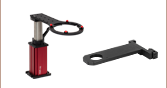
LCPN1
Dovetail Adapter
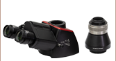
ZFM2020
Motorized Focusing Module
BSA2000
Condenser Holder
ZFM1020
Manual Focusing Module
Application Idea
CSA2000 Condenser Holder with the CSC2001 Air Condenser Attached
MCM3001
Three-Channel Controller


Please Wait

Click to Enlarge
This system uses our CSN200 Dual-Objective Nosepiece, BSA2000 Condenser Arm, and ZFM2020 and ZFM2030 modules to mount and motorize an objective and condenser.

Share Your Work With Us!
Have you built a unique setup using DIY Cerna components? Send a picture to ImagingTechSupport@thorlabs.com! Our customers often inform our engineering efforts and inspire us to make new products and improvements for the entire community. We'd love to hear from you.
Features
- Place Condensers & Macro Lenses at 7.74" Throat Depth of DIY Cerna® Systems
- Condenser Arms with Female D3N Dovetail for Thorlabs and Nikon Condensers
- Macro Lens / Condenser Arm with Internal SM2 (2.035"-40) Threads
- 60 mm Cage System Compatibility
- Focusing Modules with 1" of Z Travel Secure Condenser Holder to Microscope Body
- Motorized Modules for Fine Adjustment
- Manual Modules for Coarse Adjustment
- Dovetail Adapters to Attach DIY Setups to a Condenser Holder or Condenser

Click to Enlarge
Our arms contain six M4 counterbores for mounting them to our focusing modules.

Thorlabs offers a selection of condenser holders that provide a variety of mechanical interfaces for mounting condensers, macro lenses, and other optical elements along the optical path of a DIY Cerna system. Our BSA2000 and CSA2000 Condenser Arms each feature a female D3N dovetail, which is Thorlabs' designation for the dovetail used by the majority of Nikon condensers for upright microscopes (see the Microscope Dovetails tab for details). The CSA2100 Condenser Arm has internal SM2 threads and is 60 mm cage compatible, allowing it to support home-built condensers or other optical assemblies.
Thorlabs also offers focusing modules, which provide 1" of travel along the Z axis. Manual focusing modules are available for condenser holders that require only coarse adjustment. For fine focusing adjustment, condenser arms connect to the microscope body via our motorized focusing modules. For optics that do not require frequent adjustment, we also offer fixed mounting arms that mount lens tubes and cage systems directly along the optical path of the microscope.
This page also contains two dovetail adapters for home-built setups; the CSA2001 can connect a condenser to an SM2 lens tube system, while the LCPN1 can connect a condenser holder to an SM30 lens tube system or a 30 mm or 60 mm cage system.
| Thorlabs Dovetail Referencea | |||
|---|---|---|---|
| Type | Shape | Outer Dimension | Angle |
| 95 mm | Linear | 95 mm | 45° |
| D1N | Circular | Ø2.018" | 60° |
| D2Nb | Circular | Ø1.50" | 90° |
| D2NBb | Circular | Ø1.50" | 90° |
| D3N | Circular | Ø45 mm | 70° |
| D5N | Circular | Ø1.58" | 90° |
| D6N | Circular | Ø1.90" | 90° |
| D7N | Circular | Ø2.05" | 90° |
| D1T | Circular | Ø1.50" | 60° |
| D3T | Circular | Ø1.65" | 90° |
| D1Y | Circular | Ø107 mm | 60° |
| D2Y | Circular | Ø2.32" | 50° |
| D3Y | Circular | Ø1.75" | 90° |
| D4Y | Circular | Ø56 mm | 60° |
| D5Y | Circular | Ø46 mm | 60° |
| D6Y | Circular | Ø41.9 mm | 45° |
| D1Z | Circular | Ø54 mm | 60° |
| D2Z | Circular | Ø57 mm | 60° |
| D3Z | Circular | Ø54 mm | 45° |

Click to Enlarge
This photo shows the male D1N dovetail on the trinoculars next to the female D1N dovetail on the epi-illumination arm.

Click to Enlarge
This photo shows the male 95 mm dovetail on the microscope body and the female 95 mm dovetail on the CSA1002 Fixed Arm.
Introduction to Microscope Dovetails
Dovetails are used for mechanical mating and optical port alignment of microscope components. Components are connected by inserting one dovetail into another, then tightening one or more locking setscrews on the female dovetail. Dovetails come in two shapes: linear and circular. Linear dovetails allow the mating components to slide before being locked down, providing flexible positioning options while limiting unneeded degrees of freedom. Circular dovetails align optical ports on different components, maintaining a single optical axis with minimal user intervention.
Thorlabs manufactures many components which use dovetails to mate with our own components or those of other manufacturers. To make it easier to identify dovetail compatibility, we have developed a set of dovetail designations. The naming convention of these designations is used only by Thorlabs and not other microscope manufacturers. The table to the right lists all the dovetails Thorlabs makes, along with their key dimensions.
In the case of Thorlabs’ Cerna® microscopes, different dovetail types are used on different sections of the microscope to ensure that only compatible components can be mated. For example, our WFA2002 Epi-Illuminator Module has a male D1N dovetail that mates with the female D1N dovetail on the microscope body's epi-illumination arm, while the CSS2001 XY Microscopy Stage has a female D1Y dovetail that mates with the male D1Y dovetail on the CSA1051 Mounting Arm.
To learn which dovetail type(s) are on a particular component, consult its mechanical drawing, available by clicking on the red Docs icon ( ) below. For adapters with a female dovetail, the drawing also indicates the size of the hex key needed for the locking setscrew(s). It is important to note that mechanical compatibility does not ensure optical compatibility. Information on optical compatibility is available from Thorlabs' web presentations.
For customers interested in machining their own dovetails, the table to the right gives the outer diameter and angle (as defined by the drawings below) of each Thorlabs dovetail designation. However, the dovetail's height must be determined by the user, and for circular dovetails, the user must also determine the inner diameter and bore diameter. These quantities can vary for dovetails of the same type. One can use the intended mating part to verify compatibility.
In order to reduce wear and simplify connections, dovetails are often machined with chamfers, recesses, and other mechanical features. Some examples of these variations are shown by the drawings below.

Click to Enlarge
Two examples of how circular male dovetails can be manufactured.

Click to Enlarge
Two examples of how circular female dovetails can be manufactured.
Standard Mechanical Interfaces on DIY Cerna® Components
The table below gives the dovetail, optical component threads, and cage system interfaces that are present on each DIY Cerna component. If a DIY Cerna component does not have one of the standard interfaces in the table, it is not listed here. Please note that mechanical compatibility does not ensure optical compatibility. Information on optical compatibility is available from Thorlabs' web presentations.
| Item # | Microscope Dovetails | Optical Component Threadsa | Cage Systemsb | |||||||||||||
|---|---|---|---|---|---|---|---|---|---|---|---|---|---|---|---|---|
| 95 mm | D1N | D2N | D2NB | D3N | D5N | D1T | D3T | D1Y | D5Y | C-Mountc (1.00"-32) |
SM1d (1.035"-40) |
SM30 (M30.5x0.5) |
SM2e (2.035"-40) |
30 mmd | 60 mme | |
| 2CM1 | Internal & External | Internal | Yes | |||||||||||||
| 2CM2 | Internal & External | Internal | Yes | |||||||||||||
| BSA2000f | Female | |||||||||||||||
| CEA1350 | Male | Female | Yes | |||||||||||||
| CEA1400 | Male | Female | Yes | |||||||||||||
| CEA1500 | Male | Female | Yes | |||||||||||||
| CEA1600 | Male | Female | Yes | |||||||||||||
| CFB1500 | Male | |||||||||||||||
| CSA1000 | Female | |||||||||||||||
| CSA1001 | Female | Internal | Yes | |||||||||||||
| CSA1002 | Female | Internal | Yes | |||||||||||||
| CSA1003 | Female | Yes | ||||||||||||||
| CSA1051 | Female | Male | ||||||||||||||
| CSA1200f,g | Yes | |||||||||||||||
| CSA1400f | Female | Yes | ||||||||||||||
| CSA1500f,h | ||||||||||||||||
| CSA2000f | Female | Internal | Yes | |||||||||||||
| CSA2001 | Female | External | ||||||||||||||
| CSA2100f | Internal | Yes | ||||||||||||||
| CSA3000(/M) | Male | |||||||||||||||
| CSA3010(/M) | Male | Yes | Yes | |||||||||||||
| Item # | 95 mm | D1N | D2N | D2NB | D3N | D5N | D1T | D3T | D1Y | D5Y | C-Mount | SM1 | SM30 | SM2 | 30 mm | 60 mm |
| CSC1001 | Male | |||||||||||||||
| CSC1002 | Male | |||||||||||||||
| CSC1003 | Male | |||||||||||||||
| CSC2001 | Male | |||||||||||||||
| CSD1001 | Male & Female | Female | ||||||||||||||
| CSD1002 | Male & Female | External | ||||||||||||||
| CSE2000 | Male & Female | Yes | ||||||||||||||
| CSE2100 | Male & Female | Female | Internal | Yes | Yes | |||||||||||
| CSE2200 | Male & Female | Female | Internal | Yes | Yes | |||||||||||
| CSN100f,i | Yes | |||||||||||||||
| CSN200i | Male | |||||||||||||||
| CSN210i | Male | |||||||||||||||
| CSN500j | Male | |||||||||||||||
| CSN510k | Male | |||||||||||||||
| CSN1201g,i | ||||||||||||||||
| CSN1202g,j | ||||||||||||||||
| CSS2001 | Female | |||||||||||||||
| LAURE1 | Male | Female | ||||||||||||||
| LAURE2 | Male | Female | ||||||||||||||
| LCPN1 | Male | Internal | Yes | Yes | ||||||||||||
| LCPN2 | Male | Internal | Yes | Yes | ||||||||||||
| LCPN3 | Male | Female | Internal | Yes | ||||||||||||
| Item # | 95 mm | D1N | D2N | D2NB | D3N | D5N | D1T | D3T | D1Y | D5Y | C-Mount | SM1 | SM30 | SM2 | 30 mm | 60 mm |
| OPX2400(/M) | Male & Female | Internal | Yes | |||||||||||||
| SM1A58 | Male | Male | Internal | External | Yes | |||||||||||
| SM2A56 | Male | External | ||||||||||||||
| TC1X | Male | |||||||||||||||
| WFA0150 | Female | |||||||||||||||
| WFA1000 | Yes | |||||||||||||||
| WFA1010 | Internal | Yes | ||||||||||||||
| WFA1020 | Internal | Yes | ||||||||||||||
| WFA1051 | Internal | Yes | ||||||||||||||
| WFA1100 | Yes | |||||||||||||||
| WFA2001 | Male & Female | Internal & External | ||||||||||||||
| WFA2002 | Male & Female | Internal | Yes | |||||||||||||
| WFA4001 | Male | Female | ||||||||||||||
| WFA4002 | Male | Female | ||||||||||||||
| WFA4003 | Male | Female | ||||||||||||||
| WFA4100 | Male | External | Internal | |||||||||||||
| WFA4101 | Male | External | Internal | |||||||||||||
| WFA4102 | Male | External | Internal | |||||||||||||
| WFA4105 | Male | External | ||||||||||||||
| WFA4106 | Male | External | ||||||||||||||
| WFA4107 | Male | External | ||||||||||||||
| WFA4108 | Male | External | ||||||||||||||
| WFA4109 | Male | External | ||||||||||||||
| WFA4110 | Male | External | ||||||||||||||
| WFA4111 | Male | External | ||||||||||||||
| WFA4112 | Male | External | ||||||||||||||
| Item # | 95 mm | D1N | D2N | D2NB | D3N | D5N | D1T | D3T | D1Y | D5Y | C-Mount | SM1 | SM30 | SM2 | 30 mm | 60 mm |
| Female | ||||||||||||||||
| Female | ||||||||||||||||
| Female | ||||||||||||||||
| Female | ||||||||||||||||
| XT95P12(/M) | Female | |||||||||||||||
| ZFM1020 | Female | |||||||||||||||
| ZFM1030 | Female | |||||||||||||||
| ZFM2020 | Female | |||||||||||||||
| ZFM2030 | Female | |||||||||||||||
Building a Cerna® Microscope
The Cerna microscopy platform's large working volume and system of dovetails make it straightforward to connect and position the components of the microscope. This flexibility enables simple and stable set up of a preconfigured microscope, and provides easy paths for later upgrades and modification. See below for a couple examples of the assembly of preconfigured and DIY Cerna microscopes.
Preconfigured Microscope Kit Design and Assembly
Walkthrough of Cerna® Microscope Kit 4
This Cerna microscope configuration is equipped with both epi- and trans-illumination modules. All Cerna preconfigured microscope kits enable individual components to be removed or substituted for complete customization.
The D1N and D2N circular dovetails align the sample viewing and epi-illumination apparatus along the optical path. The microscope body's 95 mm linear dovetail is used to secure the objective mounts and condenser mounts, as well as the transmitted light illumination module. The dovetail allows components to slide along the vertical rail prior to lockdown.
DIY Cerna Design and Assembly
Walkthrough of a DIY Microscope Configuration
This DIY microscope uses a CSA3000(/M) Breadboard Top, a CSA2001 Dovetail Adapter, our CSA1001 and CSA1002 Fixed Arms, and other body attachments and extensions. These components provide interfaces to our lens tube and cage construction systems, allowing the rig to incorporate two independent trans-illumination modules, a home-built epi-illumination path, and a custom sample viewing optical path.
DIY Microscope Configuration Assembly
The simplicity of Thorlabs optomechanical interfaces allows a custom DIY microscope to be quickly assembled and reconfigured for custom imaging applications.

| Posted Comments: | |
| No Comments Posted |
Click on the different parts of the microscope to explore their functions.

Elements of a Microscope
This overview was developed to provide a general understanding of a Cerna® microscope. Click on the different portions of the microscope graphic to the right or use the links below to learn how a Cerna microscope visualizes a sample.
Terminology
Arm: Holds components in the optical path of the microscope.
Bayonet Mount: A form of mechanical attachment with tabs on the male end that fit into L-shaped slots on the female end.
Bellows: A tube with accordion-shaped rubber sides for a flexible, light-tight extension between the microscope body and the objective.
Breadboard: A flat structure with regularly spaced tapped holes for DIY construction.
Dovetail: A form of mechanical attachment for many microscopy components. A linear dovetail allows flexible positioning along one dimension before being locked down, while a circular dovetail secures the component in one position. See the Microscope Dovetails tab or here for details.
Epi-Illumination: Illumination on the same side of the sample as the viewing apparatus. Epi-fluorescence, reflected light, and confocal microscopy are some examples of imaging modalities that utilize epi-illumination.
Filter Cube: A cube that holds filters and other optical elements at the correct orientations for microscopy. For example, filter cubes are essential for fluorescence microscopy and reflected light microscopy.
Köhler Illumination: A method of illumination that utilizes various optical elements to defocus and flatten the intensity of light across the field of view in the sample plane. A condenser and light collimator are necessary for this technique.
Nosepiece: A type of arm used to hold the microscope objective in the optical path of the microscope.
Optical Path: The path light follows through the microscope.
Rail Height: The height of the support rail of the microscope body.
Throat Depth: The distance from the vertical portion of the optical path to the edge of the support rail of the microscope body. The size of the throat depth, along with the working height, determine the working space available for microscopy.
Trans-Illumination: Illumination on the opposite side of the sample as the viewing apparatus. Brightfield, differential interference contrast (DIC), Dodt gradient contrast, and darkfield microscopy are some examples of imaging modalities that utilize trans-illumination.
Working Height: The height of the support rail of the microscope body plus the height of the base. The size of the working height, along with the throat depth, determine the working space available for microscopy.
 Click to Enlarge
Cerna Microscope Body

Click to Enlarge
Body Details
Microscope Body
The microscope body provides the foundation of any Cerna microscope. The support rail utilizes 95 mm rails machined to a high angular tolerance to ensure an aligned optical path and perpendicularity with the optical table. The support rail height chosen (350 - 600 mm) determines the vertical range available for experiments and microscopy components. The 7.74" throat depth, or distance from the optical path to the support rail, provides a large working space for experiments. Components attach to the body by way of either a linear dovetail on the support rail, or a circular dovetail on the epi-illumination arm (on certain models). Please see the Microscope Dovetails tab or here for further details.
 Click to Enlarge
Illumination with a Cerna microscope can come from above (yellow) or below (orange). Illumination sources (green) attach to either.
Illumination
Using the Cerna microscope body, a sample can be illuminated in two directions: from above (epi-illumination, see yellow components to the right) or from below (trans-illumination, see orange components to the right).
Epi-illumination illuminates on the same side of the sample as the viewing apparatus; therefore, the light from the illumination source (green) and the light from the sample plane share a portion of the optical path. It is used in fluorescence, confocal, and reflected light microscopy. Epi-illumination modules, which direct and condition light along the optical path, are attached to the epi-illumination arm of the microscope body via a circular D1N dovetail (see the Microscope Dovetails tab or here for details). Multiple epi-illumination modules are available, as well as breadboard tops, which have regularly spaced tapped holes for custom designs.
Trans-illumination illuminates from the opposite side of the sample as the viewing apparatus. Example imaging modalities include brightfield, differential interference contrast (DIC), Dodt gradient contrast, oblique, and darkfield microscopy. Trans-illumination modules, which condition light (on certain models) and direct it along the optical path, are attached to the support rail of the microscope body via a linear dovetail (see Microscope Dovetails tab or here). Please note that certain imaging modalities will require additional optics to alter the properties of the beam; these optics may be easily incorporated in the optical path via lens tubes and cage systems. In addition, Thorlabs offers condensers, which reshape input collimated light to help create optimal Köhler illumination. These attach to a mounting arm, which holds the condenser at the throat depth, or the distance from the optical path to the support rail. The arm attaches to a focusing module, used for aligning the condenser with respect to the sample and trans-illumination module.
 |
 |
 |
 |
 |
 |
 |
 |
| Epi-Illumination Modules | Breadboards & Body Attachments |
Brightfield | DIC | Dodt | Condensers | Condenser Mounting | Light Sources |
 Click to Enlarge
Light from the sample plane is collected through an objective (blue) and viewed using trinocs or other optical ports (pink).
Sample Viewing/Recording
Once illuminated, examining a sample with a microscope requires both focusing on the sample plane (see blue components to the right) and visualizing the resulting image (see pink components).
A microscope objective collects and magnifies light from the sample plane for imaging. On the Cerna microscope, the objective is threaded onto a nosepiece, which holds the objective at the throat depth, or the distance from the optical path to the support rail of the microscope body. This nosepiece is secured to a motorized focusing module, used for focusing the objective as well as for moving it out of the way for sample handling. To ensure a light-tight path from the objective, the microscope body comes with a bellows (not pictured).
Various modules are available for sample viewing and data collection. Trinoculars have three points of vision to view the sample directly as well as with a camera. Double camera ports redirect or split the optical path among two viewing channels. Camera tubes increase or decrease the image magnification. For data collection, Thorlabs offers both cameras and photomultiplier tubes (PMTs), the latter being necessary to detect fluorescence signals for confocal microscopy. Breadboard tops provide functionality for custom-designed data collection setups. Modules are attached to the microscope body via a circular dovetail (see the Microscope Dovetails tab or here for details).


 Click to Enlarge
The rigid stand (purple) pictured is one of various sample mounting options available.
Sample/Experiment Mounting
Various sample and equipment mounting options are available to take advantage of the large working space of this microscope system. Large samples and ancillary equipment can be mounted via mounting platforms, which fit around the microscope body and utilize a breadboard design with regularly spaced tapped through holes. Small samples can be mounted on rigid stands (for example, see the purple component to the right), which have holders for different methods of sample preparation and data collection, such as slides, well plates, and petri dishes. For more traditional sample mounting, slides can also be mounted directly onto the microscope body via a manual XY stage. The rigid stands can translate by way of motorized stages (sold separately), while the mounting platforms contain built-in mechanics for motorized or manual translation. Rigid stands can also be mounted on top of the mounting platforms for independent and synchronized movement of multiple instruments, if you are interested in performing experiments simultaneously during microscopy.
 |
 |
 |
 |
 |
| Translating Platforms | Rigid Stands | Translation Stages for Rigid Stands | Motorized XY Stages | Manual XY Stage |
For sample viewing, Thorlabs offers trinoculars, double camera ports, and camera tubes. Light from the sample plane can be collected via cameras, photomultiplier tubes (PMTs), or custom setups using breadboard tops. Click here for additional information about viewing samples with a Cerna microscope.
| Product Families & Web Presentations | |||
 |
|
 |
 |
| Sample Viewing | Breadboards & Body Attachments |
Cameras | PMTs |
Microscope objectives are held in the optical path of the microscope via a nosepiece. Click here for additional information about viewing a sample with a Cerna microscope.
| Product Families & Web Presentations | ||||
 |
 |
 |
 |
 |
| Objectives | Objective Thread Adapters | Parfocal Length Extender | Piezo Objective Scanner | Objective Mounting |
Large and small experiment mounting options are available to take advantage of the large working space of this microscope. Click here for additional information about mounting a sample for microscopy.
| Product Families & Web Presentations | ||||
|
|
|
|
 |
| Translating Platforms | Rigid Stands | Translation Stages for Rigid Stands | Motorized XY Stages | Manual XY Stage |
Thorlabs offers various light sources for epi- and trans-illumination. Please see the full web presentation of each to determine its functionality within the Cerna microscopy platform.
| Product Families & Web Presentations | ||||
 |
 |
 |
 |
|
| Trans-Illumination Kits | Solis™ High-Power LEDs | Mounted LEDs | X-Cite® Lamps | Other Light Sources |
Epi-illumination illuminates the sample on the same side as the viewing apparatus. Example imaging modalities include fluorescence, confocal, and reflected light microscopy. Click here for additional information on epi-illumination with Cerna.
| Product Families & Web Presentations | ||
|
|
|
| Epi-Illumination | Body Attachments | Light Sources |
Trans-illumination illuminates from the opposite side of the sample as the viewing apparatus. Example imaging modalities include brightfield, differential interference contrast (DIC), Dodt gradient contrast, oblique, and darkfield microscopy. Click here for additional information on trans-illumination with Cerna.
| Product Families & Web Presentations | ||||||
|
|
|
|
 |
|
|
| Brightfield | DIC | Dodt | Condensers | Condenser Mounting | Illumination Kits | Other Light Sources |
The microscope body provides the foundation of any Cerna microscope. The 7.74" throat depth provides a large working space for experiments. Click here for additional information about the Cerna microscope body.
| Product Families & Web Presentations | |
 |
 |
| Microscope Bodies | Microscope Translator |

 Zoom
Zoom
Click for Details
Here, a CSC1001 Condenser is mounted at a 7.74" throat depth using a CSA2000 Condenser Arm and a ZFM2020 Motorized Focusing Module.

- BSA2000: Female D3N Dovetail, Two Adjusters, and Slim Profile
- CSA2000: Female D3N Dovetail, Orthogonal XY Adjusters, and 60 mm Cage Compatibility
- CSA2100: Internal SM2 (2.035"-40) Threads and 60 mm Cage Compatibility
- Attach to Focusing Module for 1" of Z Travel
These arms are designed to mount condensers at the 7.74" throat depth of DIY Cerna® systems. All of these arms contain six M4 counterbores for direct attachment to either a motorized or manual focusing module (sold separately below).
The BSA2000 arm has a D3N dovetail that is directly compatible with any condenser offered by Thorlabs; the condenser is secured using a 2 mm hex setscrew. With a thickness of just 0.52", this arm conserves valuable space along the optical axis for items like our DIC accessories, Fast XY Scanning Stage, and user-built add-ons. It includes two adjusters with ±2.5 mm travel, allowing optimization of the illumination provided by the condenser.
In comparison, the CSA2000 arm, which also has a female D3N dovetail, is 1.86" thick so that it can incorporate orthogonal XY adjusters with ±2 mm travel. These adjusters therefore offer significantly reduced crosstalk, enabling faster optimization of the illumination conditions. Witness lines below the D3N dovetail give a reference for how far the condenser has traveled. In addition, the arm contains four Ø6 mm bores for 60 mm cage systems on the top, four 4-40 taps for 60 mm cage systems on the bottom, and 0.38" deep internal SM2 (2.035"-40) threads on the bottom.
The CSA2100 arm has a 0.38" thickness, internal SM2 through threads, and four 4-40 through taps for 60 mm cage systems. The use of our standard SM2 threads makes it compatible with any custom optical system mounted using our Ø2" lens tubes, as well as the CSA2001 D3N Dovetail Adapter sold below, which can be used to adapt it to our condensers.
For machining a holder utilizing non-standard threading or condenser attachment, consider the CSA1500 blank arm, which can also be attached to a motorized focusing module.
In addition, both the BSA2000 and CSA2000 are compatible with the LCPN1 condenser adapter for DIY setups. See below for details.

 Zoom
Zoom| Manual Focusing Module Specifications | |
|---|---|
| Travel Range | 1" (25.4 mm) |
| Distance per Degree Turn of Focus Knoba |
~2 mm / 30° |
| Load Capacity | |
| Stage Mounted to Vertical Rail |
Recommended: ≤6.6 lbs (3 kg) Maximum: 11 lbs (5 kg) |
| Stage Mounted to Horizontal Rail |
Recommended: ≤22 lbs (10 kg) Maximum: 33 lbs (15 kg) |

When using the ZFM1020 module, the surface of the condenser holder will be flush with the bottom (or top) of the module.
When using the ZFM1030 module, the bottom surface of the condenser holder will be at the middle of the module.
- Provides Manual Focusing Adjustment over 1" Travel Range
- 95 mm Dovetail Clamp on Back Connects to Microscope Body
- Includes Six M4 Cap Screws for Attaching Condenser Arm
- Aligns Condenser Holder at 7.74" Throat Depth of DIY Cerna® System
- Adjust Translation Stage Using Focusing Knobs
Our Manual Condenser Focusing Modules provide 1" of manual travel for a mounted condenser and its holder. Each module consists of a 95 mm dovetail clamp that connects to the microscope body, a manual translation stage, and a mounting bracket with six M4 tapped holes. These six M4 taps are spaced to mate with the M4 counterbores on our condenser holders.
When mounting a condenser holder onto one of these manual focusing modules, the optical port will be aligned at the 7.74" throat depth of the DIY Cerna system. The focusing knobs on either side of the module can be used to translate the stage. The manual translation stage utilizes a dovetail translation mechanism to minimize long-term drift compared to stages with rolling bearings. Specifications for these manual focusing modules are provided in the table to the right.
We offer two versions of these manual focusing modules to allow the user to choose whichever module makes the most efficient use of space. As shown in the drawing on the right, a condenser holder that is mounted to the ZFM1020 Focusing Module will have one surface in the same plane as the edge of the module. This module can be secured to the microscope with the holder facing up or down. By comparison, a condenser holder mounted to the ZFM1030 Focusing Module will be mounted in the middle of the module.

 Zoom
Zoom| Motorized Translation Stage Specificationsa | |
|---|---|
| Travel Range | 1" (25.4 mm) |
| Bidirectional Repeatability | 1 µm |
| Backlash | 1 µm |
| Minimum Achievable Incremental Movement |
100 nm |
| Minimum Achievable Repeatable Movement |
200 nm |
| Velocity (Max) | 7 mm/s |
| Acceleration (Max) | 11 mm/s2 |
| Cable Length | 6' (1.8 m) |
| Pin Diagram | Click to View |
| Load Capacity | |
| Stage Mounted to Vertical Railb |
Recommended: ≤10 lbs (4.5 kg) Maximum: 10 lbs (4.5 kg) |
| Stage Mounted to Horizontal Rail |
Recommended: ≤33.5 lbs (15.2 kg) Maximum: 42 lbs (19.1 kg) |
| Stepper Motor Specifications | |
| Thread Screw Pitch | 0.3 mm |
| Step Angle | 1.8° |
| Limit Switches | Hall Effect Sensors |
| Phase Current | 0.49 A |
| Phase Resistance | 5.1 Ω |
| Phase Inductance | 1.5 mH |
| Insulation Resistance | 20 MΩ |
- Provides Motorized Focusing Adjustment over 1" Travel Range
- 95 mm Dovetail Clamp on Back Connects to Microscope Body
- Includes Six M4 Cap Screws for Attaching Condenser Arm
- Aligns Optical Port of Arm at 7.74" Throat Depth of DIY Cerna® System
- Operated by MCM3001 3-Axis Controller (Sold Separately)
Our Motorized Focusing Modules provide 1" of fine, variable-speed travel along the Z axis for optics in a DIY Cerna system. Each module consists of a 95 mm dovetail clamp that connects to the microscope body, a motorized translation stage, and a mounting bracket with six M4 tapped holes. As shown in the image below, these six M4 taps are spaced to mate with the M4 counterbores on our condenser arms. A permanently attached 6' (1.8 m) cable connects the module to our MCM3001 3-Axis Controller (sold separately below).
We offer two versions of these stepper motor modules in order to allow the user to mount the arm in whatever manner makes the most efficient use of space. As shown in the drawing below, an arm that is mounted to the ZFM2020 Motorized Module will have one surface in the same plane as the edge of the module. Since this module can be secured to the microscope body in either of two orientations, both of which are shown in the image below, the arm can be positioned at the top or the bottom. In comparison, an arm that is mounted to the ZFM2030 Motorized Module will have one surface in the plane that bisects the module, which is 1.5" away from the module's edge.
When an arm is used with one of these modules, its optical port will be aligned at the 7.74" throat depth of the DIY Cerna system. The ZFM2020 and ZFM2030 modules use the same motorized translation stage; its specifications are given in the table to the right.
Click to Enlarge
Our motorized focusing modules attach to condenser arms using six M4 cap screws.

Click to Enlarge
The ZFM2020 module has two possible orientations, creating space along the optical path for a condenser attached to an arm.

When using the ZFM2020 module, the surface of the arm will be flush with the bottom (or top) of the module.
When using the ZFM2030 module, the surface of the arm will be at the middle of the module.

 Zoom
Zoom
| Compatible Stages | |
|---|---|
| Motorized Focusing Modules | |
| Translation Stages for Rigid Stands |
| Controller Specifications |
|---|
| Compatible Motor Specifications |
|---|
- Designed for Cerna Components with 1" Motorized Travel
- Knobs Provide Hand-Operated Control for up to Three Axes
- Each Axis can be Individually Disabled to Prevent
Unintended Movements or to Retain a Position - Adjust Translation Speed via Top-Located Knob
The MCM3001 3-Axis Controller consists of a hand-operated knob box and a separate controller, as shown in the photo to the right. Each side face of the knob box includes a rotating knob and a push-button switch that are dedicated to a single axis. The push-button switch enables and disables the axis, and is lit in green when the axis is enabled. Disabling the axis lets the user preserve a position or prevent accidental movements. A smaller knob on the top face adjusts the amount of translation per rotation of the knob (see the Controller Specifications table for details).
Since each MCM3001 controller has three channels, you only need to purchase enough channels for each of the modules you intend to drive. For example, a Cerna microscope equipped with a ZFM2020 Motorized Focusing Module (which has one axis) and a PLS-XY Translation Stage (two axes) would only require one MCM3001 controller.
The MCM3001 is compatible with motorized Cerna components that have a travel range of 1", such as our Motorized Focusing Modules and Translation Stages for Rigid Stands; see the Compatible Motor Specifications table for use with alternate motorized products. For components with a 2" travel range, such as our Translating Platforms, the MCM3002 controller should be used instead. If you would like a controller configured to drive more than one type of stage, please contact Tech Support.
SDK and LabVIEW examples are also available by contacting Tech Support.

 Zoom
Zoom

Click to Enlarge
Our CSA2001 adapter has a female D3N dovetail that mates to the male D3N dovetail on a condenser. Here, the external SM2 threads on the adapter are threaded into our CXY2 mount.
| Item # | CSA2001 | LCPN1 |
|---|---|---|
| Dovetaila | Female D3N | Male D3N |
| SM Threading | External SM2 (2.035"-40) |
External SM30 (30.5 x 0.5) |
| Cage Compatibility | Noneb | 30 mm Cage System (4-40 Tapc, 4 Places) 60 mm Cage System (Ø6 mm Bore, 4 Places) |
| Clear Aperture | Ø1.58" (40.0 mm) | Ø1.10" (27.9 mm) |
| Adapter Profile (Click for Drawing) |
- Extends Versatility of Thorlabs' Lens Tube and Cage Construction Systems to DIY Cerna® Systems
- CSA2001: Female D3N Dovetail and External SM2 Threads
- LCPN1: Male D3N Dovetail, Internal SM30 Threads, 30 mm and 60 mm Cage Compatible
These dovetail adapters allow DIY light conditioning setups to be integrated into a Cerna microscope. The CSA2001 is used to mount a condenser to an optical assembly that uses Thorlabs' SM2 lens tubes. A 2 mm hex setscrew is included to secure the dovetail of the adapter to the condenser. The LCPN1 is used to mount a custom condenser configuration onto a Cerna Microscope. The adapter includes two SM30RR retaining rings to secure an optic to the inside of the adapter.
See the table to the right for the mechanical features of each adapter.