 Products Home
PRO8 Laser Diode Current Control Modules

- Ultra-Stable Current Control
- Extensive Laser Diode Protection
- External Modulation of Laser Output
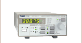
LDC8080
Module
LDC8040
Module
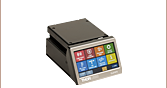
LDC8040 & TED8040 Modules
Inside a PRO800 Chassis


Please Wait
| PRO8 Laser Diode Current Control Module Options | |||||||
|---|---|---|---|---|---|---|---|
| Item # | LDC8001 | LDC8002 | LDC8005 | LDC8010 | LDC8020 | LDC8040 | LDC8080 |
| Max Laser Diode Current |
±100 mA | ±200 mA | ±500 mA | ±1 A | ±2 A | ±4 A | ±8 A |
| Module Width | 1 Slot | 2 Slots | |||||
| PRO8 Series Optionsa | |
|---|---|
| Laser Diode Current Controllers (Up to 8 A) |  |
| TEC Temperature Controllers (Up to 64 W) | |
| Combination Laser Diode Current (Up to 1 A) & TEC Temperature Controllers (Up to 16 W) |
|
| DWDM DFB Laser Modulesb | |
| Optical Switches | |
| Photocurrent Measurement Modules | |
Features
- Current Ranges: 0 to ±100 mA, ±200 mA, ±500 mA, ±1 A, ±2 A, ±4 A, ±8 A
- Supports Anode Ground (AG) and Cathode Ground (CG) Polarities
- Supports Constant Current (CC) and Constant Power (CP) Operation
- 3 dB Analog Modulation Bandwidth DC up to 200 kHz
- 16-Bit Setting Resolution
- Full Laser Protection
Introduction
Our Laser Diode Controller Modules for the PRO8 platform have extremely low current noise and drift, resulting in "best in class" laser stability performance.
Seven Current Ranges
Seven different current controller modules are available, with maximum output currents ranging from 100 mA up to 8 A. The drive current can be set precisely with 16-bit resolution – one part in 65,000. All LDC8000 Modules can be operated in either constant current (CC), or constant power (CP) mode.
User-Friendly Controls
The PRO8 display menu allows easy configuration of any module in the chassis. Mnemonic symbols provide user-friendly access to all operational parameters. All settings are retained in memory and automatically recalled upon powering on the mainframe, as long as modules have not been moved to a different slot.
Built-in Laser Diode Protection Features
The LDC8000 Series Current Control Modules incorporate proven laser protection features to safeguard sensitive laser diodes. Besides common protection functions, such as current limits, soft start and interrupt protection, an advanced circuit design ensures that AC power-line transients or power outages, as well as RF pickup can not affect the laser diode.
For each current module, three independent limits can be set to safeguard the laser. Two of the limits are programmable and prevent the laser current and the laser power from exceeding the user defined maximum values. The third limit is set via a recessed front panel trim-pot that defines a “hardware” current limit and protects against programming errors and accidential adjustment of the front panel knob. Even while externally modulating the laser current, it is not possible to exceed either the hard or soft limits, whichever is lower. After activating the laser diode a soft-start function smoothly increases the laser current without overshoots and spikes.
Even in the case of an AC power interruption, the laser current remains transient-free. Voltage peaks on the AC line are effectively suppressed by electronic filters, shielding of the transformer, and careful grounding of the modules and chassis. The LDC8000 Series meets the international requirements regarding laser protection (e.g. CDRH US21 CFR 1040.10 and IEC 60825-1). All PRO8 systems include a key-operated power switch and an interlock.
To connect an LDC8001, LDC8002, LDC8005, LDC8010, LDC8020, or LDC8040 current controller to our TEC Mounts, a CAB400 cable (length 1.5 m) is required and can be ordered below. Note: Thorlabs does not offer a compatible cable for the LDC8080.
For further information, please contact our Tech Support Team.
| Item # | LDC8001 | LDC8002 | LDC8005 | LDC8010 | LDC8020 | LDC8040 | LDC8080 |
|---|---|---|---|---|---|---|---|
| Current Control | |||||||
| Control Range (Continuous) | 0 to ±0.100 A | 0 to ±0.200 A | 0 to ±0.500 A | 0 to ±1 A | 0 to ±2 A | 0 to ±4 A | 0 to ±8 Ac |
| Compliance Voltage | >2.5 V | >5 V | >5 V | >5 V | >5 V | >5 V | >5 V |
| Setting Resolution | 1.5 µA | 3 µA | 7.5 µA | 15 µA | 30 µA | 70 µA | 130 µA |
| Setting Accuracy (Full Scale) | ±0.05% | ±0.05% | ±0.05% | ±0.1% | ±0.1% | ±0.1% | ±0.3% |
| Noise Without Ripple (10 Hz To 10 MHz, RMS, Typical) |
<1 µA | <3 µA | <5 µA | <10 µA | <20 µA | <50 µA | <100 µA |
| Ripple (50/60 Hz, RMS, Typical) | <0.8 µA | <1 µA | <1 µA | <1.5 µA | <3 µA | <4 µA | <8 µA |
| Transients (Processor, Typical) | <10 µA | <15 µA | <30 µA | <50 µA | <80 µA | <120 µA | <200 µA |
| Transients (Other, Typical) | <0.100 mA | <0.200 mA | <0.500 mA | <1 mA | <2 mA | <4 mA | <8 mA |
| Drift 60 Min / 24 Hour (Typical, 0 - 10 Hz, at Constant Ambient Temp.) |
<0.5 µA/ <1.5 µA | <0.5 µA / <1.5 µA | <2 µA / <4 µA | <5 µA / <20 µA | <15 µA / <100 µA | <25 µA / <150 µA | <100 µA / <200 µA |
| Temperature Coefficient | <50 ppm/°C | ||||||
| Power Control | |||||||
| Control Range of Photo Current | 10 µA to 5 mA (Other Ranges Available upon Request) | ||||||
| Reverse Bias Voltage | 0 / 5 V (Switchable) | ||||||
| Resolution | 100 nA | ||||||
| Accuracy (Full Scale) | ± 0.05% | ||||||
| Current Limit | |||||||
| Setting Range (20-Turn Trim-Pot) | 0 to ≥0.100 A | 0 to ≥0.200 A | 0 to ≥0.500 A | 0 to ≥1 A | 0 to ≥2 A | 0 to ≥4 A | 0 to ≥8 A |
| Resolution | 3 µA | 6 µA | 15 µA | 30 µA | 60 µA | 130 µA | 250 µA |
| Accuracy | ±0.100 mA | ±0.200 mA | ±0.500 mA | ±2 mA | ±4 mA | ±8 mA | ±50 mA |
| Power Limit | |||||||
| Photo Current Range | 0 to 5 mA | ||||||
| Resolution | 1.25 µA | ||||||
| Accuracy | ±50 µA | ||||||
| Laser Voltage Measurement | |||||||
| Measurement Principle | 4-Wire (Improves Accuracy by Compensating for Cable Resistance) | ||||||
| Measurement Range | 0 to 5 V | ||||||
| Resolution | 0.2 mV | ||||||
| Accuracy | ±5 mV | ||||||
| Analog Modulation Input | |||||||
| Input Resistance | 10 kΩ | ||||||
| 3dB-Bandwidth, CCa | DC to 2.5 kHz | DC to 200 kHz | DC to 100 kHz | DC to 50 kHz | DC to 30 kHz | DC to 20 kHz | DC to 10 kHz |
| Modulation Coefficient, CC | 10 mA/V ± 5% | 20 mA/V ± 5% | 50 mA/V ± 5% | 100 mA/V ± 5% | 200 mA/V ± 5% | 400 mA/V ± 5% | 800 mA/V ± 5% |
| Modulation Coefficient, CP | 0.5 mA/V ± 5% | ||||||
| Rise & Fall Time, (Typical)b | <100 µs | <2 µs | <4 µs | <5 µs | <6 µs | <9 µs | <15 µs |
| Connector Type | BNC | ||||||
| General Data | |||||||
| Module Width | 1 PRO8 Slot | 2 Slots | |||||
| Laser Diode Connector | 9-pin D-Sub (f ) | 15-pin HDD-Sub (f ) | |||||
| Weight | <300 g | <500 g | <750 g | ||||
| Operating Temperature | 0 to 40 °C | ||||||
| Storage Temperature | -40 to +70 °C | ||||||
LDC8001-40 Pin Configuration

D-Type Female DB9 Pin Connector
| Pin | Connection |
|---|---|
| 1 | Output for Interlock and Status LASER ON/OFF |
| 2 | Monitor Diode Ground |
| 3 | Laser Diode Ground |
| 4 | Monitor Diode Input |
| 5 | Pin 1 Ground |
| 6 | Laser Diode Cathode (Measurement Input for Laser Diode Voltage) |
| 7 | Laser Diode Cathode (with Polarity AG) |
| 8 | Laser Diode Anode (with Polarity CG) |
| 9 | Laser Diode Anode (Measurement Input for Laser Diode Voltage) |
LDC8080 Pin Configuration

D-Type Female HD15 Pin Connector
| Pin | Connection |
|---|---|
| 1 | Laser Diode Cathode (with Polarity AG)* |
| 2 | Laser Diode Cathode (with Polarity AG)* |
| 3 | Laser Diode Ground* |
| 4 | Laser Diode Anode (with Polarity CG)* |
| 5 | Laser Diode Anode (with Polarity CG)* |
| 6 | Output for Interlock and Status LASER ON/OFF |
| 7 | Laser Diode Cathode (with Polarity AG)* |
| 8 | Laser Diode Ground* |
| 9 | Laser Diode Ground* |
| 10 | Laser Diode Anode (with Polarity CG)* |
| 11 | Laser Diode Cathode (Measurement Input for LD Voltage) |
| 12 | Monitor Diode Ground |
| 13 | Monitor Diode Input |
| 14 | Laser Diode Anode (Measurement Input for LD Voltage) |
| 15 | Ground for Pin 6 |
*To connect the laser ALL THREE PINS (1, 2, 7 and 3, 8, 9 or 4, 5, 10 and 3, 8, 9) must always be used.
LDC8001-40 Pin Configuration
D-Type Female DB9 Pin Connector
| Pin | Connection |
|---|---|
| 1 | Output for Interlock and Status LASER ON/OFF |
| 2 | Monitor Diode Ground |
| 3 | Laser Diode Ground |
| 4 | Monitor Diode Input |
| 5 | Pin 1 Ground |
| 6 | Laser Diode Cathode (Measurement Input for Laser Diode Voltage) |
| 7 | Laser Diode Cathode (with Polarity AG) |
| 8 | Laser Diode Anode (with Polarity CG) |
| 9 | Laser Diode Anode (Measurement Input for Laser Diode Voltage) |
External Modulation

LDC8080 Pin Configuration
D-Type Female HD15 Pin Connector
| Pin | Connection |
|---|---|
| 1 | Laser Diode Cathode (with Polarity AG)* |
| 2 | Laser Diode Cathode (with Polarity AG)* |
| 3 | Laser Diode Ground* |
| 4 | Laser Diode Anode (with Polarity CG)* |
| 5 | Laser Diode Anode (with Polarity CG)* |
| 6 | Output for Interlock and Status LASER ON/OFF |
| 7 | Laser Diode Cathode (with Polarity AG)* |
| 8 | Laser Diode Ground* |
| 9 | Laser Diode Ground* |
| 10 | Laser Diode Anode (with Polarity CG)* |
| 11 | Laser Diode Cathode (Measurement Input for LD Voltage) |
| 12 | Monitor Diode Ground |
| 13 | Monitor Diode Input |
| 14 | Laser Diode Anode (Measurement Input for LD Voltage) |
| 15 | Ground for Pin 6 |
*To connect the laser ALL THREE PINS (1, 2, 7 and 3, 8, 9 or 4, 5, 10 and 3, 8, 9) must always be used.
The following parts are included together with each of our LDC8000 Series Current Controllers:
- 1 LDC8000 Series Current Controller Module
- Operating Manual
| Posted Comments: | |
Volker Ebert
(posted 2020-07-28 11:46:06.983) if i modulate the LDC 8002 with an analog ramp signal e.g. from a signal generator .. is the voltage input first digitized and then added to the current source .. or remains the signal path from modulation input to laser current analog over the entire signal path
.. the manual says that the laser current can also be set via a digital interface .. does this option include the modulation input of the LDC .. ie. can i modulate the laser with the full 200 kHz band width via the digital interface ?
thanks for your answer on this bit more complicated questions !
best
Volker dpossin
(posted 2020-08-07 06:15:23.0) Dear Volker,
Thank you for your feedback. The signal remains analog over the entire signal path. As the digital inferface is designed to control the laser output current or power unfortunately it is not possible to apply modulation from there. I reached out to you in order to provide further help. craig.brideau
(posted 2017-05-09 22:30:45.657) Does the LDC8002 have a high enough compliance voltage to operate the LP488-SF20 and LP520-SF15 laser diodes? swick
(posted 2017-05-11 03:18:54.0) This is a response from Sebastian at Thorlabs. Thank you for the inquiry.
LP488-SF20 and LP520-SF15 require 7.5V and 8V forward voltage.
LDC8002 provides 5V compliance voltage, which is not enough to drive these laser diodes.
I will contact you directly for showing alternatives. |

 Zoom
Zoom
| CAB400 (9 Pin Male) Cable | |
|---|---|
| Pin # | Description |
| 1 | Interlock and Status LASER ON/OFF |
| 2 | Photodiodea |
| 3 | Laser Diode Ground |
| 4 | Photodiodeb |
| 5 | Ground for Pin 1 |
| 6 | Voltage Measurement Laser Diode Cathodec |
| 7 | Laser Diode Cathode (with Polarity Anode Grounded - AG) |
| 8 | Laser Diode Anode (with Polarity Cathode Grounded - CG) |
| 9 | Voltage Measurement Laser Diode Anodec |