 Products Home / Laser Diode Current / TEC Controller - ITC5000 Series
Laser Diode Current / TEC Controller - ITC5000 Series

- Current & Temperature Control
- 3 Current Ranges
- Very Low Noise and Drift
- For All Laser Diode Polarities
Easy-to-Use Graphical Interface
(PC Not Included)
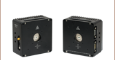
ITC5000
Module
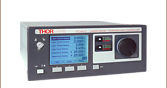
ITC5000 & LS5000
Modules in TXP5016 Chassis


Please Wait
Three Versions to Choose from:
- ITC5022: Laser Diode Current/TEC Controller ±200 mA / ±1.5 A
- ITC5052: Laser Diode Current/TEC Controller ±500 mA / ±1.5 A
- ITC5102: Laser Diode Current/TEC Controller ±1 A / ±1.5 A
ITC5000 Features
- Laser Diode Current and Temperature Control
- Very Low Noise and Drift
- Excellent Temperature Stability
- Supports All Laser Diode and Monitor Diode Polarities
- Constant Current (CC) and Constant Power (CP) Modes
- Superior Laser Diode Protection
- Internal & External Modulation
- Safe & Ultra-Stable Laser Diode Operation
Introduction
The ITC5000 Series Modules are combination laser diode and TEC controllers for the TXP platform. They allow space-saving simultaneous current and temperature control of a laser diode with a single module. The ITC5000 Series offers three laser diode current ranges, ±200 mA , ±500 mA and ±1 A, that support all laser diode and monitor diode polarities. These modules can also be modulated, externally or internally. All three models incorporate a TEC controller that provides up to ±1.5 A / 5.25 W.
Features
Besides common protection functions such as interlock and softstart, an advanced circuit design ensures that transient spikes cannot affect the laser current. The temperature controller, which is identical for all modules, is designed to keep the laser temperature constant for highly stable power and wavelength operation. Separate adjustment of the P, I and D shares of the temperature servo loop allow optimizing temperature settling times. An additional temperature window protection circuit switches the laser current off if the laser temperature leaves a preset temperature window.
The ITC5000 models offer exceptional noise and stability performance. All laser diode and photodiode pin configurations are supported.
Operation
For the operation of the ITC5000 modules a TXP chassis is required. The modules are hot-pluggable, i.e. you can insert or remove them during operation of other modules. An intuitive graphical user interface (GUI) for the ITC5000 is delivered with the TXP chassis, as well as drivers for LabVIEW™, LabWindows/CVI™, MSVC and Borland C.
Connection Cables
A CAB530 cable is required to connect the ITC5000 modules to a Thorlabs' Laser Diode Mount. The cable has to be ordered separately.
For further information, please contact our Tech Support Team.
| Laser Diode Accessory Selection Guide | |||||
|---|---|---|---|---|---|
| Temperature Controlled Mounts | Passive Mounts | Passive Mounts with Collimation Package | Strain Relief Cables | Diode Sockets | Other Controllers |
 |
 |
 |
 |
 |
 |
| Item # | ITC5022 | ITC5052 | ITC5102 |
|---|---|---|---|
| Laser Controller: Current Control | |||
| Control Range (continuous) | 0 to ±200 mA | 0 to ±500 mA | 0 to ±1 A |
| Compliance Voltage | >2.5 V (typ. >3 V) | ||
| Resolution | 4 µA | 10 µA | 20 µA |
| Accuracy (typ., f.s.) | ±100 µA | ±250 µA | ±1 mA |
| Noise without Ripple (10Hz to 10MHz, RMS, typ.) | <2 µA | <7 µA | <20 µA |
| Ripple (50Hz / 60Hz, RMS, typ.) | <0.5 µA | ||
| Transients (Processor, typ.) | <15 µA | <30 µA | <50 µA |
| Transients (other, typ.) | 200 µA | 500 µA | 1 mA |
| Drift (24hrs, at constant ambient temperature, typ.) | <2 µA | <5 µA | <20 µA |
| Temperature Coefficient | <50 ppm/°C | ||
| Laser Controller: Power Control | |||
| Control Range of Photo Current | 10 µA to 5 mA | ||
| Resolution | 0.1 µA | ||
| Accuracy (typ., f.s.) | ±5 µA | ||
| Reverse Bias Voltage | 0 to 4 V (adjustable) | ||
| Laser Controller: Current Limit | |||
| Setting Range | 0 to >200 mA | 0 to >500 mA | 0 to >1 A |
| Resolution | 50 µA | 125 µA | 250 µA |
| Accuracy (typ., f.s.) | ±200 µA | ±500 µA | ±2 mA |
| Laser Voltage Measurement | |||
| Measurement Principle | 4-Wire (improves accuracy by compensating for cable resistance) | ||
| Measurement Range | 0 to 4 V | ||
| Resolution | 0.15 mV | ||
| Accuracy | ±5 mV | ||
| External Laser Modulation | |||
| Input Resistance | 10 kΩ | ||
| Modulation Coefficient (Constant Current Mode) | 20 mA/V ± 10% | 50 mA/V ± 10% | 100 mA/V ± 10% |
| 3 dB Modulation Bandwidth (Constant Current Mode) | 200 kHz | ||
| Modulation Coefficient (Constant Power Mode) | 0.5 mA/V ± 10% | ||
| Internal Laser Modulation | |||
| Format | Sinusoidal, Triangular, Square | ||
| Frequency Range | 0.02 to 20 kHz | ||
| Rise-/Fall Time> | 4 µs | ||
| Temperature Controller: Output | |||
| Control Range of TEC Current | -1.5 A to +1.5 A | ||
| Compliance Voltage | >3.5 V | ||
| Maximum Output Power | 5.25 W | ||
| Measurement Resolution TEC Current | 60 µA | ||
| Measurement Range TEC Voltage | -4 V to +4 V | ||
| Measurement Resolution TEC Voltage | 0.2 mV | ||
| Noise and Ripple (typ.)> | <1 mA | ||
| Temperature Controller: Measurement Sensor | |||
| Sensor Type | Thermistor | ||
| Operating Range | 0.2 to 40 kΩ | ||
| Resolution | 0.8 Ω | ||
| Accuracy | ±10 Ω | ||
| Stability (24hrs) | 1 Ω | ||
| Temperature Control Loop | |||
| Type | PID, analog | ||
| Resolution P/I/D-Share Setting | 12 Bit each | ||
| TEC Current Limit | |||
| Adjustment Range | 0 to >1.5 A | ||
| Resolution via D/A Converter | 0.5 mA | ||
| Accuracy | ±20 mA | ||
| General Data | |||
| Protection Features | Global and Local Interlock, Output Short Circuit when Laser off, Laser Softstart, Laser Temperature Window, Laser and TEC Current Limits, Open Output Detection, No Sensor Detection, Over Temperature Protection | ||
| Connector Laser / TEC | 15-pin D-Sub | ||
| Connector Modulation Input | SMA | ||
| Card Width | 1 TXP Slot | ||
| Dimensions (W x G x D) | 25 mm x 130 mm x 270mm³ | ||
| Weight | 675 g | ||
| Operating Temperature | 0 to 40 °C | ||
| Storage Temperature | -40 to 70 °C | ||
| Warm-up Time | <10 min | ||
Laser Diode, Monitor Diode, TEC and Thermistor Connection

| Pin | Connection | Pin | Connection |
|---|---|---|---|
| 1 | Interlock/Status LED (LED_ILK) | 9 | Laser Diode Voltage Measurement (ULD-) |
| 2 | Monitor Diode Ground/Bias Ground (PD_GND) | 10 | Laser Diode Cathode (LDK) |
| 3 | Laser Diode Ground (LGND) | 11 | Laser Diode Anode (LDA) |
| 4 | Monitor Diode Anode or Cathode, Bias Out (PD_BIAS) | 12 | Laser Diode Voltage Measurement (ULD+) |
| 5 | Interlock Ground (DGND) | 13 | TEC Voltage Measurement (-) UTEC- |
| 6 | TEC Voltage Measurement (+) UTEC+ | 14 | Thermistor Ground (TH-) |
| 7 | TEC Plus (TEC +) | 15 | Thermistor (TH+) |
| 8 | TEC Minus (Ground) (TEC -) |
External Modulation via SMA

Voltage Range 0 - 10 V
The Software Package for the TXP5000 Platform contains the Software Modules for the ITC5000 Series
TXP Software
Version 3.1.5
Standard full TXP software packages for the ITC5000 Series:
Applications, Drivers, and Firmware.
| ITC5022 | ITC5052 | ITC5102 | Part |
|---|---|---|---|
| x | Laser Diode Current/TEC Controller ±200 mA / ±1.5 A (ITC5022) | ||
| x | Laser Diode Current/TEC Controller ±500 mA / ±1.5 A (ITC5052) | ||
| x | Laser Diode Current/TEC Controller ±1 A / ±1.5 A (ITC5102) | ||
| x | x | x | Operating Manual |
PID Basics
The PID circuit is often utilized as a control loop feedback controller and is very commonly used for many forms of servo circuits. The letters making up the acronym PID correspond to Proportional (P), Integral (I), and Derivative (D), which represents the three control settings of a PID circuit. The purpose of any servo circuit is to hold the system at a predetermined value (set point) for long periods of time. The PID circuit actively controls the system so as to hold it at the set point by generating an error signal that is essentially the difference between the set point and the current value. The three controls relate to the time-dependent error signal; at its simplest, this can be thought of as follows: Proportional is dependent upon the present error, Integral is dependent upon the accumulation of past error, and Derivative is the prediction of future error. The results of each of the controls are then fed into a weighted sum, which then adjusts the output of the circuit, u(t). This output is fed into a control device, its value is fed back into the circuit, and the process is allowed to actively stabilize the circuit’s output to reach and hold at the set point value. The block diagram below illustrates very simply the action of a PID circuit. One or more of the controls can be utilized in any servo circuit depending on system demand and requirement (i.e., P, I, PI, PD, or PID).

Through proper setting of the controls in a PID circuit, relatively quick response with minimal overshoot (passing the set point value) and ringing (oscillation about the set point value) can be achieved. Let’s take as an example a temperature servo, such as that for temperature stabilization of a laser diode. The PID circuit will ultimately servo the current to a Thermo Electric Cooler (TEC) (often times through control of the gate voltage on an FET). Under this example, the current is referred to as the Manipulated Variable (MV). A thermistor is used to monitor the temperature of the laser diode, and the voltage over the thermistor is used as the Process Variable (PV). The Set Point (SP) voltage is set to correspond to the desired temperature. The error signal, e(t), is then just the difference between the SP and PV. A PID controller will generate the error signal and then change the MV to reach the desired result. If, for instance, e(t) states that the laser diode is too hot, the circuit will allow more current to flow through the TEC (proportional control). Since proportional control is proportional to e(t), it may not cool the laser diode quickly enough. In that event, the circuit will further increase the amount of current through the TEC (integral control) by looking at the previous errors and adjusting the output in order to reach the desired value. As the SP is reached [e(t) approaches zero], the circuit will decrease the current through the TEC in anticipation of reaching the SP (derivative control).
Please note that a PID circuit will not guarantee optimal control. Improper setting of the PID controls can cause the circuit to oscillate significantly and lead to instability in control. It is up to the user to properly adjust the PID gains to ensure proper performance.
PID Theory
The output of the PID control circuit, u(t), is given as

where
Kp= Proportional Gain
Ki = Integral Gain
Kd = Derivative Gain
e(t) = SP - PV(t)
From here we can define the control units through their mathematical definition and discuss each in a little more detail. Proportional control is proportional to the error signal; as such, it is a direct response to the error signal generated by the circuit:

Larger proportional gain results is larger changes in response to the error, and thus affects the speed at which the controller can respond to changes in the system. While a high proportional gain can cause a circuit to respond swiftly, too high a value can cause oscillations about the SP value. Too low a value and the circuit cannot efficiently respond to changes in the system.
Integral control goes a step further than proportional gain, as it is proportional to not just the magnitude of the error signal but also the duration of the error.

Integral control is highly effective at increasing the response time of a circuit along with eliminating the steady-state error associated with purely proportional control. In essence integral control sums over the previous error, which was not corrected, and then multiplies that error by Ki to produce the integral response. Thus, for even small sustained error, a large aggregated integral response can be realized. However, due to the fast response of integral control, high gain values can cause significant overshoot of the SP value and lead to oscillation and instability. Too low and the circuit will be significantly slower in responding to changes in the system.
Derivative control attempts to reduce the overshoot and ringing potential from proportional and integral control. It determines how quickly the circuit is changing over time (by looking at the derivative of the error signal) and multiplies it by Kd to produce the derivative response.

Unlike proportional and integral control, derivative control will slow the response of the circuit. In doing so, it is able to partially compensate for the overshoot as well as damp out any oscillations caused by integral and proportional control. High gain values cause the circuit to respond very slowly and can leave one susceptible to noise and high frequency oscillation (as the circuit becomes too slow to respond quickly). Too low and the circuit is prone to overshooting the SP value. However, in some cases overshooting the SP value by any significant amount must be avoided and thus a higher derivative gain (along with lower proportional gain) can be used. The chart below explains the effects of increasing the gain of any one of the parameters independently.
| Parameter Increased | Rise Time | Overshoot | Settling Time | Steady-State Error | Stability |
|---|---|---|---|---|---|
| Kp | Decrease | Increase | Small Change | Decrease | Degrade |
| Ki | Decrease | Increase | Increase | Decrease Significantly | Degrade |
| Kd | Minor Decrease | Minor Decrease | Minor Decrease | No Effect | Improve (for small Kd) |
Tuning
In general the gains of P, I, and D will need to be adjusted by the user in order to best servo the system. While there is not a static set of rules for what the values should be for any specific system, following the general procedures should help in tuning a circuit to match one’s system and environment. In general a PID circuit will typically overshoot the SP value slightly and then quickly damp out to reach the SP value.
Manual tuning of the gain settings is the simplest method for setting the PID controls. However, this procedure is done actively (the PID controller turned on and properly attached to the system) and requires some amount of experience to fully integrate. To tune your PID controller manually, first the integral and derivative gains are set to zero. Increase the proportional gain until you observe oscillation in the output. Your proportional gain should then be set to roughly half this value. After the proportional gain is set, increase the integral gain until any offset is corrected for on a time scale appropriate for your system. If you increase this gain too much, you will observe significant overshoot of the SP value and instability in the circuit. Once the integral gain is set, the derivative gain can then be increased. Derivative gain will reduce overshoot and damp the system quickly to the SP value. If you increase the derivative gain too much, you will see large overshoot (due to the circuit being too slow to respond). By playing with the gain settings, you can maximize the performance of your PID circuit, resulting in a circuit that quickly responds to changes in the system and effectively damps out oscillation about the SP value.
| Control Type | Kp | Ki | Kd |
|---|---|---|---|
| P | 0.50 Ku | - | - |
| PI | 0.45 Ku | 1.2 Kp/Pu | - |
| PID | 0.60 Ku | 2 Kp/Pu | KpPu/8 |
While manual tuning can be very effective at setting a PID circuit for your specific system, it does require some amount of experience and understanding of PID circuits and response. The Ziegler-Nichols method for PID tuning offers a bit more structured guide to setting PID values. Again, you’ll want to set the integral and derivative gain to zero. Increase the proportional gain until the circuit starts to oscillate. We will call this gain level Ku. The oscillation will have a period of Pu. Gains are for various control circuits are then given below in the chart.
| Posted Comments: | |
jens
(posted 2010-03-29 16:43:49.0) A reply from Jens at Thorlabs to dianfan: Being able to temperature stabilize or place a butterfly type laser diode in equilibrium depends on the heat generated by the laser as well as the mount that the device is mounted to. If there are temperature gradients, external contribution then the PID control may oscillate trying stabilize but never achieving the steady state. In the first step we will need to know which mount you are using, is it our LM14S2 butterfly mount? We would suggest to run the TEC part of the diode and see how stable the temperature gets at various temperature set points . You should be able to track the resistance change with temperature. You could try to turn the laser diode on with low power so not to over heat the unit until you sure on the TEC level. See if the TEC responds by the feedback value produced by the thermistor.
You mentioned "switching the thermistor in an oscilloscope to help the PID setting". We will have to discuss directly with you what exactly you are measuring in this step. The thermistor is a resistive element that changes its value according to temperature. A 10K type is typically at 25 deg C. This value is read by the controller via bridge compared to the actual temperature set and an error signal if any is used in the feedback to correct the TEC drive current. We will contact you directly to provide further assistance. dianfan
(posted 2010-03-29 11:25:05.0) Thorlabs Techsupport,
My lab bought Thorlabs’ ITC5102 to control a DFB laser (LUCENT’s D2526),
but the controller can not make the temperature stable. The steps and
phenomena as followed:
1. Connecting the D-SUB’s pin with the DFB laser according to the 1.6
connecting components in the operation manual.
2. Dealing with the interlock problem.
3. Inputting thermistor’s R0, T0 and B-Value in the temperature control.
4. Turning on the TEC and adjusting the PID.
5. Whatever the P-, I- and D-share setting, the “temperature not
stabilized” always displaying in the error control and temperature
fluctuation is ±1? at best.
6. According to a senior fellow’s suggestion, switching the thermistor
in an oscilloscope to help the PID setting.
7. However, the voltage between the thermistor only 15~20mV overlying a
200~250Hz noise whose amplitude is about 5mV.
I do not think the controller could measure the thermistor resistance
with such low voltage. Could you explain what is wrong in it?
Please give me some advice how to control the temperature stable. If
this problem is not solved, the LD can not be turned on.
Looking forward you reply
Dian Fan
Center for Photonics Technology
Bradley Department of Electrical and Computer Engineering
Virginia Tech
dianfan@vt.edu demin.ma
(posted 2007-07-24 23:12:47.0) Dear ..
We need 2 types of TEC controller OEM products with small size, their specfication as follows:
UNIT controller1 controller1
temperature control precision: 0C 0.1 0.1
temperature adjustable range: 0C 15-35 15-30
operative environment temperature: 0C 0-50 0-50
Heat generated by Controlling Object : W 5 50
Would you please tell you whether you can build /design such OEM product? Please reply me as soon as possible
best regards
2007/07/25
Ma demin
EE engineer of NLight corp. |