 Products Home / Optical Elements / Optical Filters / Spectral Filters / Edgepass Filters: Longpass and Shortpass
Edgepass Filters: Longpass and Shortpass
- Shortpass and Longpass Filters
- May be Combined for Custom Bandpass Filtering
- 0.01% Max Transmission in Rejection Region
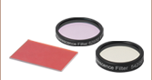
- Available in Kits
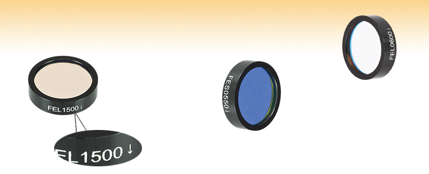
FEL1500
Engraving Indicates Recommended
Transmission Direction
FES0550
FEL0600


Please Wait


| Longpass Filters | Shortpass Filters |
|
|---|---|---|
| Transmission Region | Cut-on λ to 2200 nm (Min) | 0.7λ to Cut-off λ (Unless 0.7λ is < 400 nm, then 400 nm to Cut-off λ) |
| Rejection Region | 200 nm to Cut-on λ | 1.3 times Cut-off λ |
Features
- 1" Outer Diameter (Ø21.0 mm Clear Aperture)
- Order Sorting Filters for Photometry
- Stray Light or Trim Filters to Eliminate any Unwanted Near-Band Radiation
- Raman Spectroscopy Filters
- Astronomy Applications
Thorlabs' longpass and shortpass filters are very useful for isolating regions of a spectrum. These edgepass filters feature durable dielectric coatings that withstand the normal cleaning and handling necessary when using any high-quality optical component. Their film construction is essentially a modified quarter-wave stack, using interference effects rather than absorption, to isolate their spectral bands (see the Specs tab for transmission information).
Unlike colored filter glass, the cut-on and cut-off wavelength of these filters will shift to a shorter wavelength as the angle of incidence is increased. As a rule of thumb, when the angle of incidence goes from 0° to 45°, the central wavlength shifts down by about 10%. This feature can be useful in applications where it is desirable to fine tune the location of the cut-on, or cut-off wavelength. In addition, our edgepass filters are hermetically sealed to provide maximum humidity protection, and they can be stacked to create a custom bandpass filter.
Please note: The edgepass filters on this page are not tested or recommended for fluorescence applications. Please see our premium hard-coated edgepass filters for use in fluorescence applications.
| Webpage Feature | |
|---|---|
| |
Clicking on this symbol in the tables below will open a window showing transmission and optical density data for the corresponding filter. |
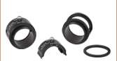
Each filter is housed in a black anodized aluminum ring that is labeled with an arrow indicating the design propagation direction. The ring makes handling easier and enhances the blocking OD by limiting scattering. These filters can be mounted in our extensive line of filter mounts and wheels. As the mounts are not threaded, Ø1" retaining rings will be required to mount the filters in one of our internally-threaded SM1 lens tubes. We do not recommend removing the filter from its mount, as the filter consists of several layers of glass that are held together with epoxy and the mounting ring. These glass layers are necessary to protect the dielectric coating from the atmosphere; exposure would significantly reduce the filter's transmission efficiency over time.
These longpass and shortpass filters are also available in kits. To request a quote for custom edgepass filters, please contact Tech Support. For applications with demanding wavefront requirements, such as imaging, please consider our premium edgepass filters.
| Longpass Filters | Shortpass Filters | |
|---|---|---|
| Transmission Region | Cut-on λ to 2200 nm Minimum | 0.7λ to Cut-off λ (Unless 0.7λ is < 400 nm, Then 400 nm to Cut-off λ) |
| Transmission at Peaka | 400 - 700 nm, 80% 750 - 1000 nm, 75% >1000 nm, 70% |
550 - 1000 nm, 80% <550 nm, 70% |
| Cut-On or Cut-Off Tolerance (Δλ @ 50% of Peak) |
±3 nm (400 to 750 nm) ±15 nm (800 to 1500 nm) |
±3 nm (450 to 750 nm) ±15 nm (800 to 1000 nm) |
| Rejection Region | 200 nm to Cut-On | 1.3 Times Cut-Off |
| Transmission in Rejection Region | 0.01% abs. (OD > 4.0) | 0.01% abs., 0.0001% avg. (OD > 4.0) |
| Cut-off Slope | 3%, OD = 0.3 to OD = 4 | 4-5%, OD = 0.3 to OD = 4 |
| Construction | Immersed Dielectric | |
| Surface Quality (Scratch-Dig) | 80-50 per Mil-0-13830A | |
| Substrate Material | Soda Lime or Equivalent | |
| Clear Aperture | Ø21.0 mm | |
| Diameter | 1" (25.4 mm) | |
Optical Density Equation:

Click to Enlarge
The number of layers shown in this schematic is not indicative of the number of layers in an actual bandpass filter. Also the drawing is not to scale.
Bandpass/Edgepass Filter Structure
A bandpass or edgepass filter is created by depositing layers of material on the surface of the substrate. Typically, there are several dielectric stacks separated by spacer layers. The dielectric stack is composed of a large number of alternating layers of low-index and high-index dielectric material. The thickness of each layer in the dielectric stack is λ/4, where λ is the central wavelength of the bandpass filter (i.e. the wavelength with the highest transmittance through the filter). The spacer layers are placed in between the dielectric stacks and have a thickness of (nλ)/2, where n is an integer. The spacer layers can be formed from colored glass, epoxy, dyes, metallic, or dielectric layers. A Fabry-Perot cavity is formed by each spacer layer sandwiched between dielectric stacks. The filter is mounted in an engraved metal ring for protection and ease of handling.
Filter Operation Overview
The constructive interference conditions of a Fabry-Perot cavity allow light at the central wavelength, and a small band of wavelengths to either side, to be transmitted efficiently, while destructive interference prevents the light outside the passband from being transmitted. However, the band of blocked wavelengths on either side of the central wavelength is small. In order increase the blocking range of the filter, materials with broad blocking ranges are used for or coated onto the spacer layers and the substrate. Although these materials effectively block out of band transmission of incident radiation they also decrease the transmission through the filter in the passband.

FB800-10 and FB800-40 filters were used to make the measurement that resulted in the plot above.
Filter Orientation
An engraved arrow on the edge of the filter is used to indicate the recommended direction for the transmission of light through the filter. Although the filter will function with either side facing the source, it is better to place the coated side toward the source. This will minimize any thermal effects or possible thermal damage that blocking intense out-of-band radiation might cause due to the absorption of the out-of-band radiation by the substrate or colored glass filter layers. The plot to the right was made by illuminating the filter with a low intensity broadband light and measuring the transmission as a function of wavelength. The plot shows that the transmission direction through the filter has very little effect on the intensity and the spectrum of the light transmitted through the filter. The minimal variation between the forward and backward traces is most likely due to a small shift in the incident angle of the light on the filter introduced when the filter was removed, flipped over, and replaced in the jig.
The filter is intended to be used with collimated light normally incident on the surface of the filter. For uncollimated light or light striking the surface and an angle not normally incident to the surface the central wavelength (wavelength corresponding to peak transmission) will shift toward lower wavelengths and the shape of the transmission region (passband) will change. As a rule of thumb, when the angle of incidence goes from 0° to 45°, the central wavlength shifts down by about 10%. This feature can be useful in applications where it is desirable to fine tune the location of the cut-on, or cut-off wavelength.
Filter Temperature
The central wavelength of the bandpass filter can be tuned slightly (~1 nm over the operating range of the filter) by changing the temperature of the filter. This is primarily due to the slight thermal expansion or contraction of the layers.
| Posted Comments: | |
Eberhard Riedle
(posted 2020-12-06 11:13:37.923) please indicate the substrate thickness and the refractive index YLohia
(posted 2021-01-06 02:43:37.0) Hello, based on our direct conversation, you were specifically interested in this information for the FES0500, FES0550, and the FESH0700. FES0550 has an index of 1.7 at 550 nm and has a substrate thickness of 4.5mm. The index for FESH0700's substrate can be found here (https://www.thorlabs.com/images/TabImages/UVFS_Sellmeier_G3-780.gif index) and has a substrate thickness of 2.0 mm. This information for other part numbers can be requested by emailing techsupport@thorlabs.com. ersen.beyatli
(posted 2018-12-10 11:03:27.877) Dear Sales Person
For one of my project I am interested in a longpass filter with cut-on wavelength 2000 nm. Do you have or can you you build such king of filter and what will be the price of it.
thanks
ersen YLohia
(posted 2018-12-12 12:27:24.0) Hello Ersen, thank you for contacting Thorlabs. Custom optics can be requested by emailing techsupport@thorlabs.com. I will reach out to you directly to discuss the possibility of offering this. f.jahantigh
(posted 2018-11-20 22:03:31.597) With greetings
For more information about your products, including FEL0750 and FES0800, I need more information, including optical intensity and total power which is collected at the aperture of the receiver.
Many thanks. nbayconich
(posted 2018-11-26 02:20:09.0) Thank you for contacting Thorlabs. We provide Transmission & OD vs. wavelength plots which you can use to estimate the total power transmitted through these filters.
The raw transmission data can be downloaded under the Transmission Data Icons. chungpo
(posted 2018-06-27 13:32:29.32) Do you have data for 45 deg (or any off normal) angle of incidence? YLohia
(posted 2018-07-03 10:36:04.0) Hello, I have reached out to you directly with that data. r.kamarudheen
(posted 2017-06-21 02:17:22.663) Hi, I'd like to know if you could make custom specified 500 mm short pass filters, with a transmission of 30-50% above 500 nm? Thanks nbayconich
(posted 2017-06-27 02:31:16.0) Thank you for contacting Thorlabs. I will reach out to you directly with more information on our custom capabilities. lasereng
(posted 2016-12-28 17:39:30.783) Hi, I'd like to know the damage threshold for this item, specifically FEL1050, and specifically at 1030nm. Can't seem to find it listed on this page.
Thanks,
Alex Rubin
Photonics, LLC tfrisch
(posted 2016-12-30 02:52:32.0) Hello Alex, thank you for contacting Thorlabs. While we don't have any damage threshold testing for The FEL and FES series filters, I can say that the damage threshold would be low. The construction involves multiple layers of dielectric and absorbing layers connected by adhesive, and that adhesive would be limiting. I will reach out to you directly about alternatives such as our hard coated filters. smou
(posted 2016-12-26 17:12:26.683) I am interested in an FEL0900 and FEL1500 filter, but with 8.5mm diameter. Is that available on a custom order? tfrisch
(posted 2016-12-27 03:04:40.0) Hello, thank you for contacting Thorlabs. Our Technical Support team will reach out to you directly about these customs. weilun
(posted 2016-08-10 13:37:43.727) do you have the data about refection for the low transmission range jlow
(posted 2016-08-17 10:28:52.0) Response from Jeremy at Thorlabs: We only specify the transmission characteristic for these filters. chuck.malone
(posted 2016-07-18 20:34:05.587) what is the thickness of the filter FEL1350 aaron.b.potter
(posted 2016-01-08 11:16:33.923) I am interested in an FEL1000 filter, but with 12.7mm diameter. Is that available on a custom order? besembeson
(posted 2016-01-12 02:15:43.0) Response from Bweh at Thorlabs USA: We can provide this to you as a custom item. I will contact you. liangguanquan
(posted 2015-07-29 00:28:06.063) I need a filter 2 inch in diameter, highly reflecting 532 nm and highly transmitting 390 nm. Do you have corresponding products? and price? besembeson
(posted 2015-09-23 07:21:48.0) Response from Bweh at Thorlabs USA: A suggestion you may consider for 45deg AOI will be the HBSY22 found at the following link: http://www.thorlabs.com/newgrouppage9.cfm?objectgroup_id=7035 grovyle
(posted 2015-04-13 13:32:58.277) Do you have these filters on 1/2" diameter?
I'd like to use them inside a SM05L05, in between the sphere outlet and a screwed-in SM05SMA (which goes out to a fiber-coupled spectrometer). besembeson
(posted 2015-04-21 06:24:51.0) Response from Bweh at Thorlabs USA: We can provide this to you as a special item. I will follow-up by email for a quotation. esoto
(posted 2015-04-10 17:24:15.83) I need a short pass filter of 12,5 mm (0,5 inches)
without frame or mounting (bare), which will cut beginning at 700 to 1100 nm or 750 to 1100 nm
with OD more than 4
must have transmitance at least beginning from 350 nm
do you have someting like that or similar??
thanks
Ed jlow
(posted 2015-04-16 01:25:02.0) Response from Jeremy at Thorlabs: I will contact you directly about quoting this. pallysally
(posted 2014-08-01 00:00:43.8) can these filters be used for femtosecond laser? besembeson
(posted 2014-08-07 03:53:02.0) Response from Bweh E at Thorlabs: These would not be a great choice for short pulse systems. The base material for these filters is Soda Lime which is an economy grade material. Because of the potential for high power with the short pulses the premium edge pass filters would be a better choice. These can be found at the following link: http://www.thorlabs.com/newgrouppage9.cfm?objectgroup_id=1860. ben
(posted 2014-07-18 12:43:11.72) Does this filter come in smaller sizes? besembeson
(posted 2014-07-23 09:10:46.0) A response from Bweh at Thorlabs USA: Hello, we certainly can provide smaller sizes for this filter. I will follow up by email to get your special requirements. hussain
(posted 2014-05-20 04:47:27.983) Would you pls tell me the transmission of FEL1200 from 4-5µm. besembeson
(posted 2014-05-21 12:03:55.0) This is a response from Bweh Esembeson at Thorlabs: Thanks for your inquiry. This filter doesn't transmit in the 4-5 micron range. The blocking optical density will be at least 2. tuomas
(posted 2014-01-08 07:14:44.71) What is the effective refractive index of your filters? I.e. the quantity N_e discussed in http://www.irf.se/~urban/avh/html/node17.html jlow
(posted 2014-01-29 03:58:49.0) Response from Jeremy at Thorlabs: The effective refractive index is generally used to estimate the central wavelength shift for angle tuning. It seems that you are looking to achieve a certain cut-off wavelength that we do not carry. We can do a transmission scan for you at different angles for a specific filter. I will get in contact with you to arrange this. guoqiang.xia
(posted 2013-03-04 01:43:47.503) The is a follow up on the previous question. The following data are a short section of transmission data of FEL0800, there are negative values, please verify your measurements. Thanks!
706 1.97E-05
705 -1.06E-06
704 5.04E-06
703 -4.71E-07
702 8.78E-06
701 1.32E-06
700 -4.57E-06 guoqiang.xia
(posted 2013-02-27 01:15:11.893) About transmition data on your website, why are there negative values? Especially in the rejected region, since we are very concerned with the performance in the rejected region, so please clarify that at the OD 6-8 region, your measurements are not noise plagued. sharrell
(posted 2012-06-20 10:17:00.0) Response from Sean at Thorlabs: Thank you for your feedback on our longpass filters page. I am sorry that the filter was not available for purchase on the page, we have corrected the error and it is now available for purchase. The plot on the page has also been updated. m.c.ashby
(posted 2012-06-20 08:00:13.0) is the FEL0600 filter available? It is not on the list of order numbers and data shown is for FLE0650. bdada
(posted 2012-01-10 12:22:00.0) Response from Buki at Thorlabs:
As a guideline, the power density should no more than 1W/cm2 for CW and 0.15J/cm2 (10ns, 532nm, .508mm) for pulsed lasers. The filter will not be able to withstand 1kW/cm^2. Please contact TechSupport@thorlabs.com if you have further questions. sven
(posted 2012-01-09 15:14:42.0) Is there any LIDT data for these filters? In my special case: Are the FEL0450/FES0500 filters able to withstand ~1kW/cm² cw? bdada
(posted 2011-12-26 12:10:00.0) Response from Buki at Thorlabs:
Thank you for your feedback. The direction of the incident light does matter. Please refer to the excerpt from the "Tutorial" tab on the website. We will look into how to make this information clearer in our packaging and on our website. Please contact TechSupport@thorlabs.com if you have any questions.
"An engraved arrow on the edge of the filter is used to indicate the recommended direction for the transmission of light through the filter. Although the filter will function with either side facing the source, it is better to place the coated side toward the source. This will minimize any thermal effects or possible thermal damage that blocking intense out-of-band radiation might cause due to the absorption of the out-of-band radiation by the substrate or colored glass filter layers." user
(posted 2011-12-22 17:52:19.0) Does the direction of the incident light matter, there seems to be an arrow on the outer edge of the filter, but nothing is said in the presentation or on the packaging. jjurado
(posted 2011-08-31 18:35:00.0) Response from Javier at Thorlabs to smuehlen: Dielectric coated filters such as our short and long pass filters do not affect the polarization state of the incident beam. However, at angles of incidence greater than 0°, the parallel (p) and perpendicular (s) polarization components of light are filtered differently. This effect, which includes changes in the transmission profile and a shortening in the cut-on wavelength, become more pronounced as the angle of incidence increases. I will contact you directly with more information. smuehlen
(posted 2011-08-30 11:23:15.0) Do the filters have any influence on the polarization of the transmitted beam? bdada
(posted 2011-04-15 16:55:00.0) Response from Buki at Thorlabs:
As a guideline, the power density should no more than 1W/cm2 for CW and 0.15J/cm2 (10ns, 532nm, .508mm) for pulsed lasers. Note that the amount of energy in the transmitting region and the blocking region should be considered. For example, the amount of energy the FEL1000 filter is subjected to at 1200nm (transmitted) will be more than the amount of energy it is subjected to at 800nm (absorbed).
Please contact TechSupport@thorlabs.com if you have further questions. jmod1g09
(posted 2011-04-15 16:15:20.0) Hello,
What is the maximum out of band (rejected/reflected) power density permited before damage? jjurado
(posted 2011-04-14 13:56:00.0) Response from Javier at Thorlabs to David de Castro Alves: Thank you very much for submitting your request. If the purpose of your application is to block the transmission of light at the harmonic wavelength and pass light at the fundamental wavelength, then the FEL0700 longpass filter would work, with a transmission of ~81% at 1232 nm. Alternatively, you can use a shortpass dichroic mirror such as our DMSP1000, which has reflection band of 1020-1550 nm with (Ravg > 90%) and a transmission band of 520-985 nm (Tavg > 90%). Here is the link for this mirror: http://www.thorlabs.com/NewGroupPage9.cfm?ObjectGroup_ID=3313&pn=DMSP1000
I will contact you directly for further support. dmvalves
(posted 2011-04-14 16:20:36.0) Hi,
I need to remove the following wavelength 1232nm from is second harmonic 616nm. In the filter datasheet there are no information about the 1232nm transmission. It is possible to tell me the transmission to the fundamental wavelength (1232nm)?
Best regards,
David de Castro Alves jjurado
(posted 2011-02-07 09:56:00.0) Response from Javier at Thorlabs to Pramod: Thank you very much for contacting us with your request. We are currently in the process of adding raw data for most of our optics products as a standard across our entire website. This includes all of our interference filters. In the meantime, please contact our Technical Support department at techsupport@thorlabs.com so that we can send you these files directly.
We can also provide these filter unmounted. user
(posted 2011-02-04 18:38:25.0) I will greatly appreciate transmission data for FEL1050, FEL1100, FEL1150, FEL1200, FEL1250, FEL1300, FEL1350, FEL1400, FEL1450, and FEL1500 in the range 900nm to 1800nm.
I already have these filters, and would like to have another set without mounts.
Pramod pkkhulbe
(posted 2011-02-04 18:37:33.0) I will greatly appreciate transmission data for FEL1050, FEL1100, FEL1150, FEL1200, FEL1250, FEL1300, FEL1350, FEL1400, FEL1450, and FEL1500 in the range 900nm to 1800nm.
I already have these filters
Pramod Thorlabs
(posted 2010-11-05 09:52:08.0) Response from Javier at Thorlabs to Tristan: I will send you this information shortly. tristan.deborde
(posted 2010-11-05 01:43:16.0) Can I please get transmission data on the FEL1000 for a wavelength range going from 400 to 2000 nm? Thorlabs
(posted 2010-10-27 16:12:16.0) Response from Javier at Thorlabs to Tristan: I will contact you directly with this information. tristan.deborde
(posted 2010-10-26 23:19:27.0) Do you have more Transmission data for the FES1000 and FEL1000. Im interested in about 450 nm up to posted graph for FES1000 and out to 2000 nm for FEL1000 if possible? Thorlabs
(posted 2010-10-15 18:13:40.0) Response from Javier at Thorlabs to Angela: I will contact you directly with a quotation for this filter. angelakyea
(posted 2010-10-15 10:41:50.0) I want to purchase two of the FEL0400 long pass filter,
What is the cost of both the product price and the shipping price?
And how is the payment done please? Thorlabs
(posted 2010-09-08 16:32:24.0) Response from Javier at Thorlabs to bmangum: I will send you an Excel file with typical data for the transmission and optical density of the FEL0450 filter. bmangum
(posted 2010-09-08 13:36:23.0) I have an FEL0450. Is there a way of getting the ascii data?
Also it is more helpful to have a plot of the optical density vs wavelength compared to % transmission. Thorlabs
(posted 2010-07-09 17:46:27.0) Response from Javier at Thorlabs to wwu: thank you for your feedback. As a general guideline, the central wavelength of the filter will shift to a lower wavelength by about 10% as you rotate the filter form 0 to 45 degrees. For the FEL0800, this translates into a total shift of ~80 nm. Also, the tranmission percentage decreases and the profile of the passband changes slightly. wwu
(posted 2010-07-09 15:21:58.0) What is the expected wavelength shift in cut-off frequency when one rotates the filter? Single nm? or tens of nm? My interest is specfically in the FEL0800 filter. Adam
(posted 2010-05-14 08:21:35.0) A response from Adam at Thorlabs to to vkhopov: As you rotate the filter from normal incidence, the cut off frequency will shift to lower wavelengths and broaden out. Adam
(posted 2010-05-14 08:17:17.0) A response from Adam at Thorlabs to xshen: We are inspecting the FEL1100 today. We will measure the transmission at 2100nm and send you the data. xshen
(posted 2010-05-12 18:02:26.0) Hello, we just have some quesitons about the longpass 1100 nm filters. We found that there is a big dip (almost cutoff) at the wavelength around 2100 nm. Would you please send me the transmission data from 1100 - 2200 nm? klee
(posted 2009-11-30 17:00:45.0) A response from Ken at Thorlabs to physics_nt: The "V" is indeed an indicator for the beam direction. It points with the laser. physics_nt
(posted 2009-11-30 16:46:17.0) I notice a V on the side of these is that an indicator of laser propagation direction? Should it point against the laser or with the laser or is this just a part number? Tyler
(posted 2008-11-26 14:14:24.0) A response from Tyler at Thorlabs to dasfda: We are always working toward improving the quality and type of content available to our customers through the web, so thank you for your suggestion. Our web development team and our optics quality control department are working on a method of providing all of the lot specific transmission measurements made directly to the customer via the our website. Although this functionality is not currently ready to release yet, we can send you via email the transmission data and plots for any of the filters that you are interested in. To receive this information, just email our tech support department with a list of filters (include the lot number engraved on the filter mount if available). dasfda
(posted 2008-11-26 12:07:24.0) Please give the transmission data in text or CSV format as well as the graphs. One file with the whole lot in would be very useful. Please include the full wavelength range (including the bits excluded from the graphs where the transmission is ~0). Graphs in db would also be useful.
25mm mounts (not 1") would be lovely. |

 Zoom
Zoom
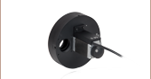
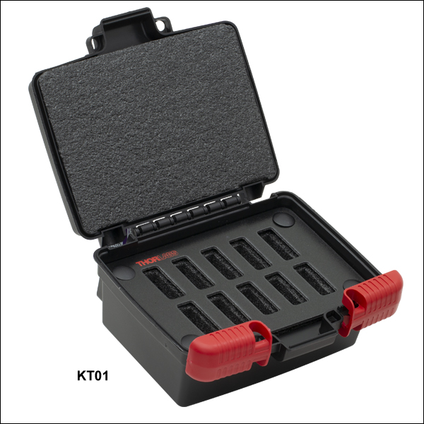
- Designed to Hold Ø25 mm and Ø50 mm Mounted ND Filters
- Protects Optics from Dust and Scratches
- Foam Inserts Separate Optics
The KT01 and KT02 are designed to hold filters that are housed in SM1-and SM2-threaded mounts respectively.