 Products Home / Technical Resources / Optical Elements Technical Publications / Non-Polarizing Beamsplitters Lab Facts
Non-Polarizing Beamsplitters Lab Facts

Please Wait

Thorlabs Lab Fact: Beamsplitter Package Matters
We present laboratory measurements of the polarization angle, split ratio, and total throughput power of a beam transmitted through Thorlabs plate, cube, and pellicle beamsplitters. While all non-polarizing beamsplitters function similarly, the exact performance is different for different types of beamsplitter. Each type of beamsplitter contains its own advantages and disadvantages compared to other types of beamsplitters. Appropriate choice of beamsplitter is essential to sensitive experimental systems. We present a complete analysis and comparison of optical parameters for three common types of non-polarizing beamsplitters.
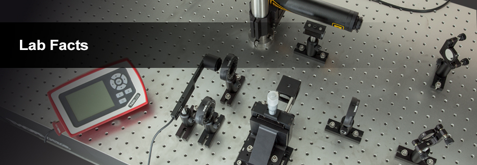
For our experiment we used the HRS015 stabilized HeNe as the light source for our investigation. A linear polarizer is used to set the laser beam's polarization axis to 45° in order to provide equal S- and P-polarized light incident on the beamsplitter. The beamsplitter under investigation was then placed in the beampath, and its split beams directed to appropriate detectors. The total power though the optic, polarization states, split ratios, and angle of incidence effects were investigated under this configuration.

The plots below summarize the measured results for all three types of beamsplitters. From these graphs the performance of each optic can be easily compared to one another. The bottom left plot summarizes the results for the total power throughput for each optic. The total power throughput is measured as the fraction of input power. While the plate and pellicle beamsplitters perform rather similarly, the cube shows signs of absorption inside the optic. Additionally, this plot shows the relative insensitivity of throughput power to angle of incidence. The bottom middle graph summarizes the results for the output polarization angle for each optic. The cube shows the most similar polarization angles between the reflected and transmitted beams, with the plate producing the largest difference in polarization between beams. The bottom right plot summarizes the results for the split ratio, as a fraction of input power, for the beamsplitters. Here it can be shown that the plate beamsplitter demonstrates the most ideal for 50/50 power splitting. For details on the experimental setup employed and the results summarized here, please click here.


| Posted Comments: | |
bruce harrison
(posted 2019-04-04 21:27:10.27) How about how beamsplitters are used as beam combiners? How does the side 2 coating come into play with the different types of splitters? How well can they combine two beams of the same wavelength and then two beams of different wavelength? YLohia
(posted 2019-04-05 04:59:46.0) Hello, thank you for your valuable feedback. We have added this to our list of tasks and intend to have this information available on our website as a future Lab Fact or just a general guide on the relevant beamsplitter pages. |