 Products Home / Motorized Stages / Motorized Rotation Stages and Mounts / Direct Drive Rotation Stage
Direct Drive Rotation Stage
- 180 rpm (3 Hz) Velocity
- 5 kg Load Capacity
- Max Axial Wobble 60 µrad
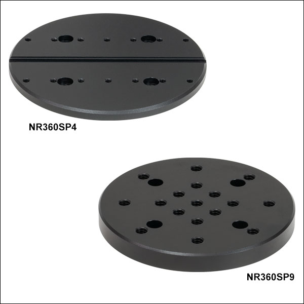
NR360SP4
Grooved Adapter Plate
NR360SP9
Threaded Adapter Plate
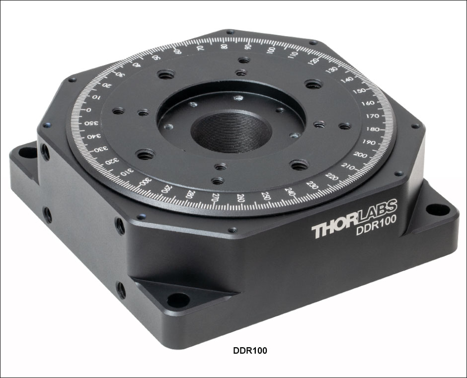
DDR100
SM1-Threaded Center Hole


Please Wait
| Key DDR100 Specificationsa | |
|---|---|
| Travel Range | 360° Continuous |
| Velocity (Max) | 180 rpm (3 Hz) |
| Max Wobble (Axial) | 60 µrad |
| Bidirectional Repeatability | 60 µrad |
| Horizontal Load Capacity (Max)b | 5.0 kg |
| Vertical Load Capacity (Max)b | 2.0 kg (Mounted Centrally) |
| Min Achievable Incremental Movement | 70 µrad |
| Cable Length | 3.0 m (9.8') |
| Recommended Controllera | BBD201 |
| Stage Dimensions (L x W x H) | 115 mm x 115 mm x 40 mm (4.53" x 4.53" x 1.58") |

Features
- 360° Continuous Rotation
- High Speeds up to 180 rpm
- Low Profile: 40 mm (1.57")
- Integrated, Brushless DC Servo Motor Actuators
- High-Quality, Precision-Engineered Bearings
- Compatible with SM1 Lens Tubes and 30 mm Cage System Components
- Compatible with NR360SP4 and NR360SP9 Adapter Plates
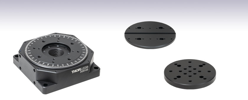
The Thorlabs' DDR100 low-profile, direct-drive rotary stage provides continuous rotation of a load up to 5 kg (11 lb) with 2 µrad resolution and a maximum rotation speed of 180 rpm. An SM1-threaded central aperture allows an optical path to pass directly through the body of the stage.
This stage has a 3-phase, brushless DC motor integrated directly into the frame of the stage. This eliminates all forms of mechanical transmission providing high repeatability, rigidity and reliability. The winding design eliminates torque ripple due to magnetic cogging, enabling good velocity stability even at low speeds. The high magnetic pole count produces a large amount of torque (0.7 N•m). The high-resolution encoder mounted directly on the moving world provides high accuracy and repeatability, while the precision-engineered bearings and tight manufacturing tolerances produce very low axial wobble (60 µrad) and radial eccentricity (6 µm). An engraved vernier scale with 1° graduations allows for coarse positioning.
The stage can be mounted horizontally on the work surface, or vertically on a Ø1"post (see the diagram to the right) or by using our AP90RL or VB01 right-angle brackets. It can also be mounted directly to the DDS300 and DDS600 translation stages. The top plate features an SM1-threaded (1.035"-40) through hole to allow Ø1" optics and our SM1 product line to be mounted. The rotating and non-rotating top surfaces, and the rear face, all feature an array of 4-40 tapped holes to integrate 30 mm cage assemblies and components.
Controller
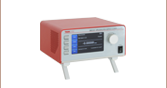
The recommended controller is the BBD201 single-axis Brushless DC Motor Controller. This controller provides a user-configurable, S-curve acceleration/deceleration profile that enables fast, smooth positioning without vibration or shock. It is ideal for motion control applications demanding operation at high speeds (hundreds of mm/s) and high encoder resolution (50 nm). The design incorporates the latest digital and analog techniques as well as high-bandwidth, high-power servo control circuitry. The controllers ship with our software for easy integration into an existing system. For multi-axis applications (e.g. when used with the DDS300 and DDS600 translation stages) the stage can also be driven by our BBD202 and BBD203 2-Axis and 3-Axis Controllers.
Adapter Plates
Adapter plates are available that fix to the rotating platform of the stage. The NR360SP4 Grooved Adapter Plate allows the stage to be used with our fiber launch systems product line. The NR360SP9 Threaded Adapter Plate has 17 1/4"-20 or M6 mounting holes and four #8 or M4 counterbored fixing holes and provides numerous options for attaching devices. See below for more details.
Joystick Option
An optional 2-axis joystick console (MJC001) is also available for remote positioning applications. See the presentation below for more details. Please note that in order to control two stages simultaneously, a multi-axis BBD202 or BBD203 controller is required.
| DDR100 Direct Drive Rotation Stage | |
|---|---|
| Travel Range | 360° Continuous |
| Velocity (Max) | 180 rpm (3 Hz) |
| Acceleration (Max)a | 7200°/s2 at 0.5 kg (1.1 lb) Load 1800°/s2 at 2.0 kg (4.4 lb) Load |
| Bidirectional Repeatability | 60 µrad |
| Backlashb | N/A |
| Encoder Resolution | 2.0 µrad (0.0001°) |
| Min Achievable Incremental Movement | 70 µrad |
| Recommended Loadc | 2 kg (4.4 lb) |
| Horizontal Load Capacity (Max)c | 5.0 kg |
| Vertical Load Capacity (Max)c | 2.0 kg (Mounted Centrally) |
| Absolute On-Axis Accuracy | 250 µrad |
| Max Burst Torque (1 Sec) | 0.7 N•m |
| Continuous Torque | 0.5 N•m |
| Settling Time | 200 ms Typical |
| Velocity Stability | 0.5% |
| Max Wobble (Axial) | 60 µrad |
| Limit Switches | None |
| Central Aperture | SM1 Threaded (1.035"-40) |
| Operating Temperature Ranged | 5 to 40 °C (41 to 104 °F) |
| Motor Type | Brushless DC Rotary Motor |
| Cable Length | 3 m (9.8') |
| Dimensions | 115 mm x 115 mm x 40 mm (4.53" x 4.53" x 1.58") |
| Weight (Excluding Cables) | 2 kg (4.4 lbs) |
| BBD201 Controller | |
|---|---|
| Drive Connector | 8-Pin DIN, Round, Female |
| Feedback Connector | 15-Pin D-Type |
| Continuous Drive Output | 2.5 A |
| PWM Frequency | 40 kHz |
| Operating Modes | Position and Velocity |
| Control Algorithm | 16-Bit Digital PID Servo Loop with Velocity and Acceleration Feedforward |
| Velocity Profile | Trapezoidal/S-Curve |
| Position Count | 32 Bit |
| Position Feedback | Incremental Encoder |
| Encoder Bandwidth | 2.5 MHz 10 M Counts/s |
| Encoder Supply | 5 V |
| AUX Control Connector | 15-Pin D-Type |
| Power Supply Input | Power: 250 VA Voltage: 100 to 240 VAC Frequency: 47 to 63 Hz Fuse: 3.15 A |
| Dimensions | 174 mm x 245 mm x 126 mm (6.85" x 9.65" x 4.96") |
| Weight | 3.46 kg (7.60 lbs) |
The flying leads are terminated in a male 15-pin D-Type and male 8-pin round DIN connector. Pin details are given below.
Feedback Connector

Motor Drive Connector

| Pin | Description | Pin | Description |
|---|---|---|---|
| 1 | Not Used | 9 | Ground |
| 2 | Ground | 10 | Limit Switch + |
| 3 | Not Used | 11 | Limit Switch - |
| 4 | Enconder Index - | 12 | Encoder Index + |
| 5 | Encoder Phase B - | 13 | Encoder Phase B + |
| 6 | Encoder Phase A - | 14 | Encoder Phase A + |
| 7a | 5 V | 15 | Not Used |
| 8a | 5 V |
| Pin | Description |
|---|---|
| 1 | Motor Phase V |
| 2 | Ground |
| 3 | Thermistor (Not Used) |
| 4 | Motor Phase U |
| 5 | Stage ID |
| 6 | Ground |
| 7 | Motor Phase W |
| 8 | Enable |
Thorlabs offers two platforms to drive our wide range of motion controllers: our Kinesis® software package or the legacy APT™ (Advanced Positioning Technology) software package. Either package can be used to control devices in the Kinesis family, which covers a wide range of motion controllers ranging from small, low-powered, single-channel drivers (such as the K-Cubes™ and T-Cubes™) to high-power, multi-channel, modular 19" rack nanopositioning systems (the APT Rack System).
The Kinesis Software features .NET controls which can be used by 3rd party developers working in the latest C#, Visual Basic, LabVIEW™, or any .NET compatible languages to create custom applications. Low-level DLL libraries are included for applications not expected to use the .NET framework. A Central Sequence Manager supports integration and synchronization of all Thorlabs motion control hardware.

Kinesis GUI Screen

APT GUI Screen
Our legacy APT System Software platform offers ActiveX-based controls which can be used by 3rd party developers working on C#, Visual Basic, LabVIEW™, or any Active-X compatible languages to create custom applications and includes a simulator mode to assist in developing custom applications without requiring hardware.
By providing these common software platforms, Thorlabs has ensured that users can easily mix and match any of the Kinesis and APT controllers in a single application, while only having to learn a single set of software tools. In this way, it is perfectly feasible to combine any of the controllers from single-axis to multi-axis systems and control all from a single, PC-based unified software interface.
The software packages allow two methods of usage: graphical user interface (GUI) utilities for direct interaction with and control of the controllers 'out of the box', and a set of programming interfaces that allow custom-integrated positioning and alignment solutions to be easily programmed in the development language of choice.
A range of video tutorials is available to help explain our APT system software. These tutorials provide an overview of the software and the APT Config utility. Additionally, a tutorial video is available to explain how to select simulator mode within the software, which allows the user to experiment with the software without a controller connected. Please select the APT Tutorials tab above to view these videos.
Software
Kinesis Version 1.14.25
The Kinesis Software Package, which includes a GUI for control of Thorlabs' Kinesis and APT™ system controllers.
Also Available:
- Communications Protocol
Software
APT Version 3.21.4
The APT Software Package, which includes a GUI for control of Thorlabs' APT™ and Kinesis system controllers.
Also Available:
- Communications Protocol
Thorlabs' Kinesis® software features new .NET controls which can be used by third-party developers working in the latest C#, Visual Basic, LabVIEW™, or any .NET compatible languages to create custom applications.
C#
This programming language is designed to allow multiple programming paradigms, or languages, to be used, thus allowing for complex problems to be solved in an easy or efficient manner. It encompasses typing, imperative, declarative, functional, generic, object-oriented, and component-oriented programming. By providing functionality with this common software platform, Thorlabs has ensured that users can easily mix and match any of the Kinesis controllers in a single application, while only having to learn a single set of software tools. In this way, it is perfectly feasible to combine any of the controllers from the low-powered, single-axis to the high-powered, multi-axis systems and control all from a single, PC-based unified software interface.
The Kinesis System Software allows two methods of usage: graphical user interface (GUI) utilities for direct interaction and control of the controllers 'out of the box', and a set of programming interfaces that allow custom-integrated positioning and alignment solutions to be easily programmed in the development language of choice.
For a collection of example projects that can be compiled and run to demonstrate the different ways in which developers can build on the Kinesis motion control libraries, click on the links below. Please note that a separate integrated development environment (IDE) (e.g., Microsoft Visual Studio) will be required to execute the Quick Start examples. The C# example projects can be executed using the included .NET controls in the Kinesis software package (see the Kinesis Software tab for details).
 |
Click Here for the Kinesis with C# Quick Start Guide Click Here for C# Example Projects Click Here for Quick Start Device Control Examples |
|
LabVIEW
LabVIEW can be used to communicate with any Kinesis- or APT-based controller via .NET controls. In LabVIEW, you build a user interface, known as a front panel, with a set of tools and objects and then add code using graphical representations of functions to control the front panel objects. The LabVIEW tutorial, provided below, provides some information on using the .NET controls to create control GUIs for Kinesis- and APT-driven devices within LabVIEW. It includes an overview with basic information about using controllers in LabVIEW and explains the setup procedure that needs to be completed before using a LabVIEW GUI to operate a device.
 |
Click Here to View the LabVIEW Guide Click Here to View the Kinesis with LabVIEW Overview Page |
|
These videos illustrate some of the basics of using the APT System Software from both a non-programming and a programming point of view. There are videos that illustrate usage of the supplied APT utilities that allow immediate control of the APT controllers out of the box. There are also a number of videos that explain the basics of programming custom software applications using Visual Basic, LabView and Visual C++. Watch the videos now to see what we mean.
 |
Click here to view the video tutorial | |
To further assist programmers, a guide to programming the APT software in LabView is also available.
|
Click here to view the LabView guide | |
Rotation Mount and Stage Selection Guide
Thorlabs offers a wide variety of manual and motorized rotation mounts and stages. Rotation mounts are designed with an inner bore to mount a Ø1/2", Ø1", or Ø2" optic, while rotation stages are designed with mounting taps to attach a variety of components or systems. Motorized options are powered by a DC Servo motor, 2 phase stepper motor, piezo inertia motor, or an Elliptec™ resonant piezo motor. Each offers 360° of continuous rotation.
Manual Rotation Mounts
| Rotation Mounts for Ø1/2" Optics | |||||||
|---|---|---|---|---|---|---|---|
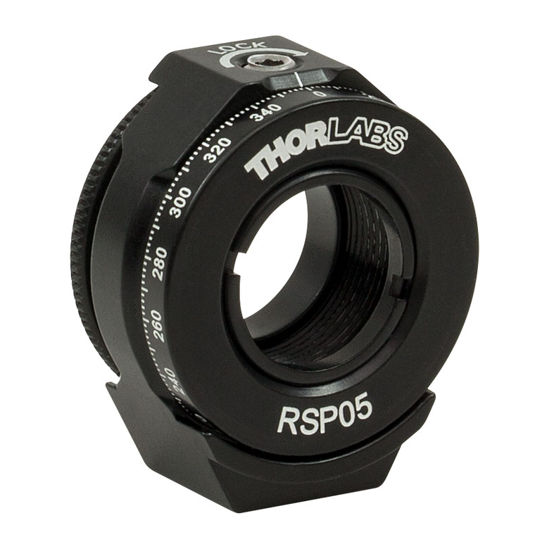
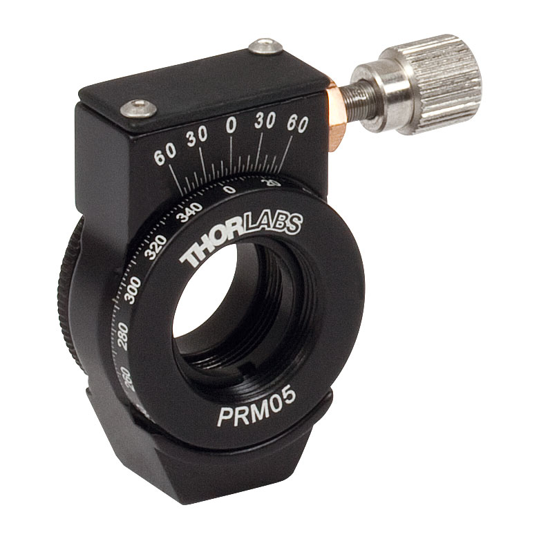
| Item # | MRM05(/M) | RSP05(/M) | CRM05 | PRM05(/M)a | SRM05 | KS05RS | CT104 |
| Click Photo to Enlarge |
 |
 |
 |
 |
 |
 |
 |
| Features | Mini Series | Standard | External SM1 (1.035"-40) Threads |
Micrometer | 16 mm Cage-Compatible | ±4° Kinematic Tip/Tilt Adjustment Plus Rotation | Compatible with CT1 Cage Translator Stage and 1/4" Translation Stagesb |
| Additional Details | |||||||
| Rotation Mounts for Ø1" Optics | ||||||||
|---|---|---|---|---|---|---|---|---|
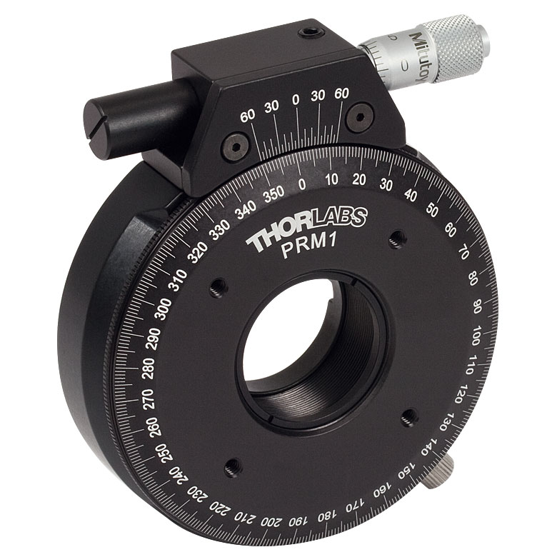
| Item # | RSP1(/M) | LRM1 | RSP1D(/M) | DLM1(/M) | CLR1(/M) | RSP1X15(/M) | RSP1X225(/M) | PRM1(/M)a |
| Click Photo to Enlarge |
 |
 |
 |
 |
 |
 |
|
 |
| Features | Standard | External SM1 (1.035"-40) Threads |
Adjustable Zero | Two Independently Rotating Carriages | Rotates Optic Within Fixed Lens Tube System |
Continuous 360° Rotation or 15° Increments |
Continuous 360° Rotation or 22.5° Increments |
Micrometer |
| Additional Details | ||||||||
| Rotation Mounts for Ø1" Optics | ||||||
|---|---|---|---|---|---|---|
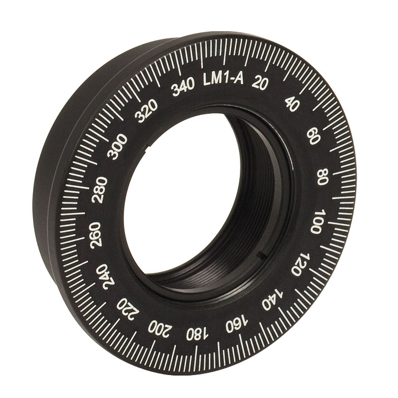
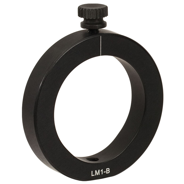
| Item # | LM1-A & LM1-B(/M) |
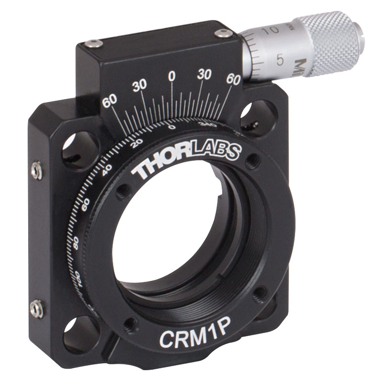
CRM1(/M) | CRM1L(/M) | CRM1P | KS1RS | K6XS |
| Click Photo to Enlarge |
  |
 |
 |
 |
 |
 |
| Features | Optic Carriage Rotates Within Mounting Ring | 30 mm Cage-Compatiblea | 30 mm Cage-Compatible for Thick Opticsa |
30 mm Cage-Compatible with Micrometera |
±4° Kinematic Tip/Tilt Adjustment Plus Rotation | Six-Axis Kinematic Mounta |
| Additional Details | ||||||
| Rotation Mounts for Ø2" Optics | |||||||
|---|---|---|---|---|---|---|---|
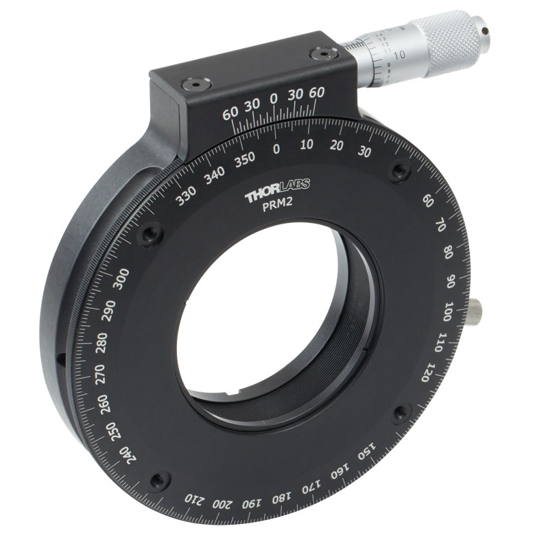
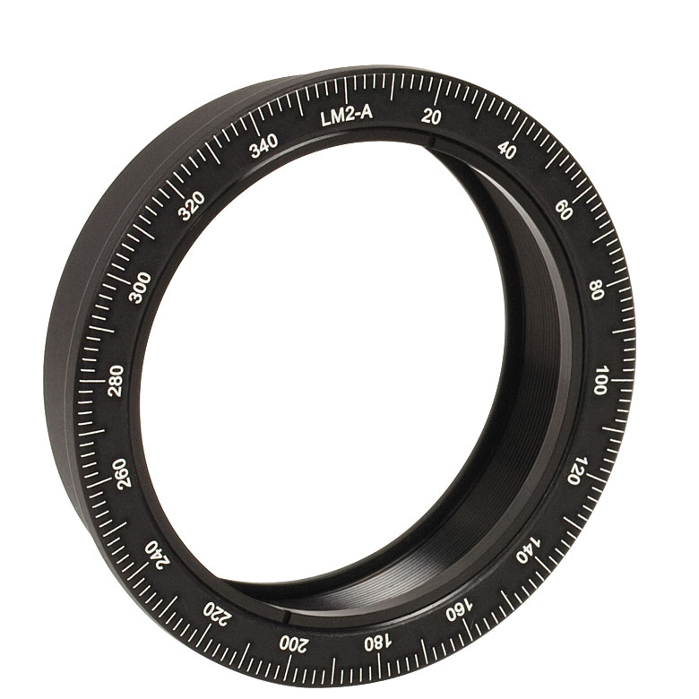
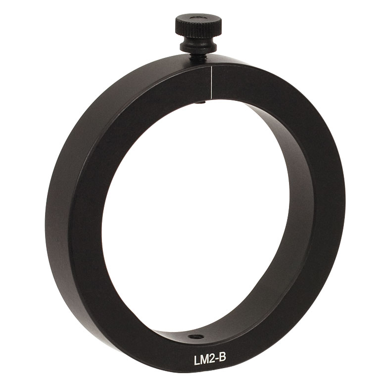
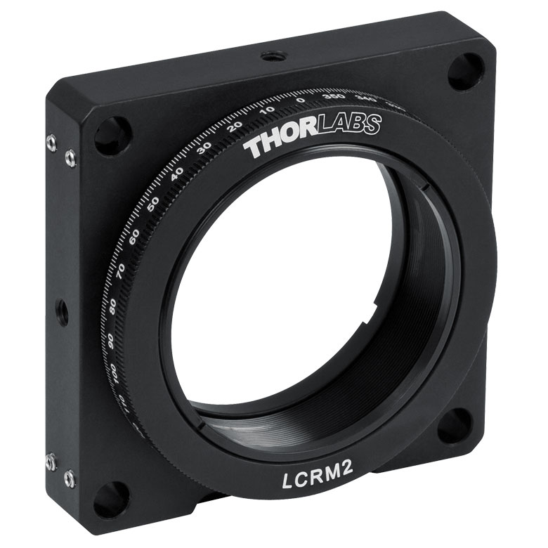
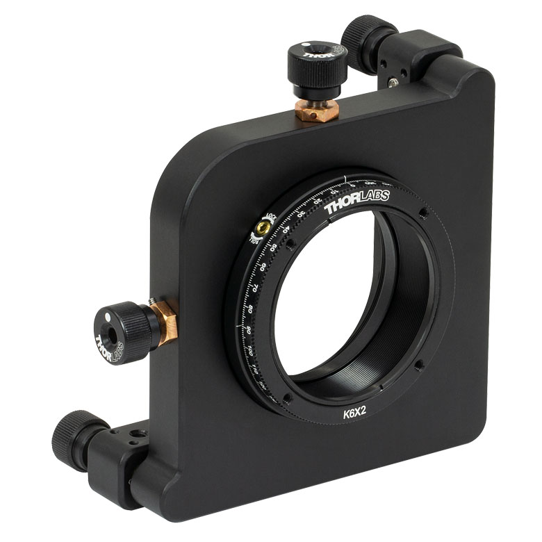
| Item # | RSP2(/M) | RSP2D(/M) | PRM2(/M) | LM2-A & LM2-B(/M) |
LCRM2(/M) | KS2RS | K6X2 |
| Click Photo to Enlarge |  |
 |
 |
  |
 |
 |
 |
| Features | Standard | Adjustable Zero |
Micrometer | Optic Carriage Rotates Within Mounting Ring | 60 mm Cage-Compatible | ±4° Kinematic Tip/Tilt Adjustment Plus Rotation | Six-Axis Kinematic Mount |
| Additional Details | |||||||
Manual Rotation Stages
| Manual Rotation Stages | ||||||
|---|---|---|---|---|---|---|
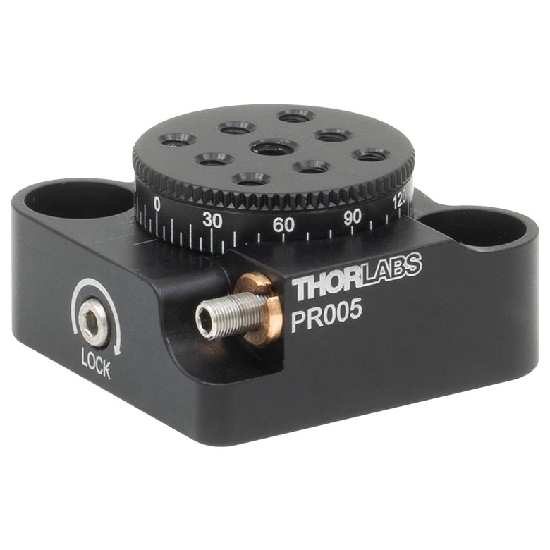
| Item # | RP005(/M) | PR005(/M) | MSRP01(/M) | RP01(/M) | RP03(/M) | QRP02(/M) |
| Click Photo to Enlarge |
 |
 |
 |
 |
 |
 |
| Features | Standard | Two Hard Stops | ||||
| Additional Details | ||||||
| Manual Rotation Stages | ||||||
|---|---|---|---|---|---|---|
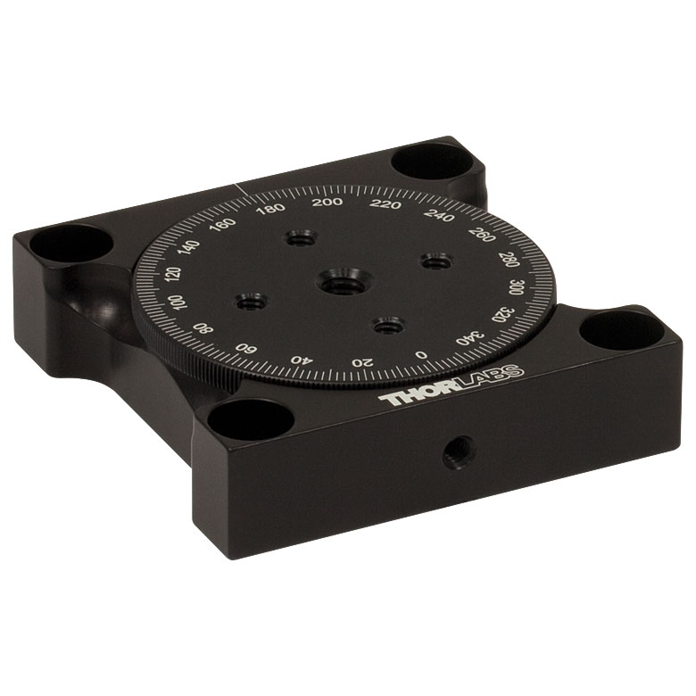
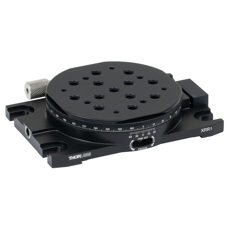
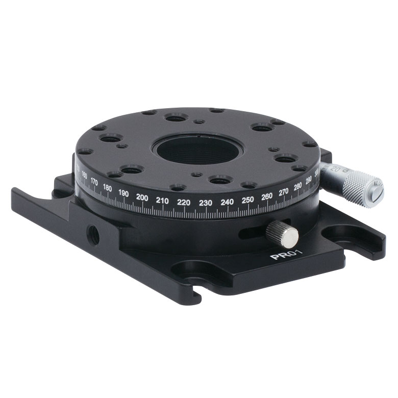
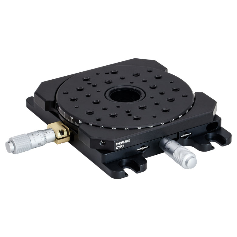
| Item # | XRNR1(/M) | XRR1(/M) | PR01(/M) | CR1(/M) | XYR1(/M) | OCT-XYR1(/M) |
| Click Photo to Enlarge |
 |
 |
 |
 |
 |
 |
| Features | Fine Rotation Adjuster and 2" Wide Dovetail Quick Connect |
Fine Rotation Adjuster and 3" Wide Dovetail Quick Connect |
Fine Rotation Adjuster and SM1-Threaded Central Aperture |
Fine Pitch Worm Gear | Rotation and 1/2" Linear XY Translation | |
| Additional Details | ||||||
Motorized Rotation Mounts and Stages
| Motorized Rotation Mounts and Stages with Central Clear Apertures | |||||||
|---|---|---|---|---|---|---|---|
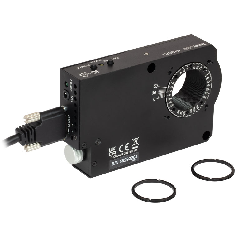
| Item # | DDR25(/M) | PDR1(/M) | K10CR1(/M) | PRM1Z8(/M)a | DDR100(/M) | ELL14 | HDR50(/M) |
| Click Photo to Enlarge |
 |
 |
 |
 |
 |
 |
 |
| Features | Compatible with SM05 Lens Tubes, 16 mm Cage System, 30 mm Cage System |
Compatible with SM05 Lens Tubes, 30 mm Cage System, PD1(/M) Linear Stages |
Compatible with SM1 Lens Tubes & 30 mm Cage System |
Compatible with SM1 Lens Tubes, 16 mm Cage System, 30 mm Cage System |
Compatible with SM1 Lens Tubes, Open Frame Design for OEM Applications |
Compatible with SM2 Lens Tubes |
|
| Additional Details | |||||||
| Motorized Rotation Mounts and Stages with Tapped Platforms | ||
|---|---|---|
| Item # | PRMTZ8(/M)a | ELL18(/M)b |
| Click Photo to Enlarge |
 |
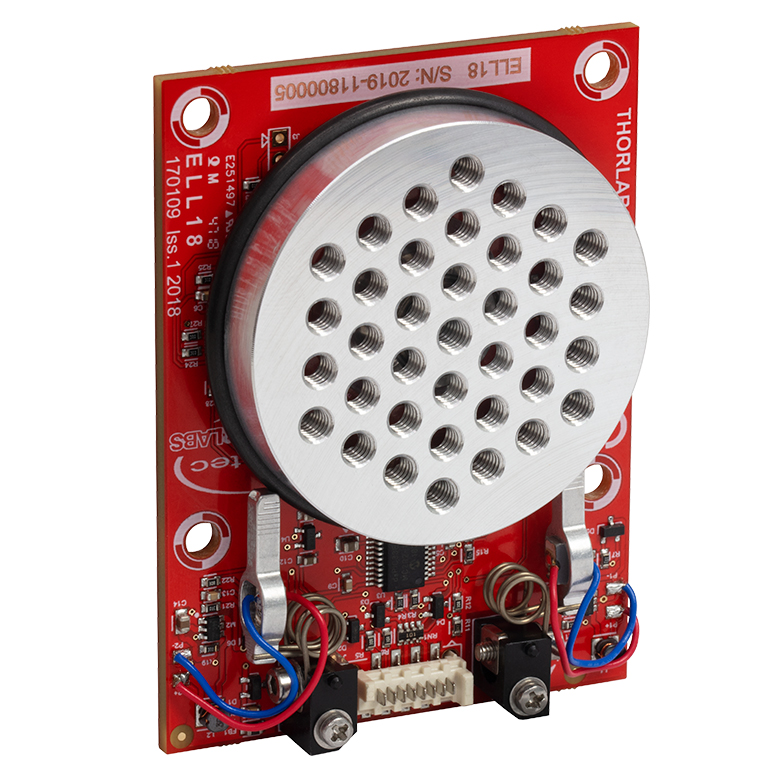 |
| Features | Tapped Mounting Platform for Mounting Prisms or Other Optics | Tapped Mounting Platform, Open Frame Design for OEM Applications |
| Additional Details | ||
| Posted Comments: | |
Henrik Madsen
(posted 2020-04-03 06:21:55.75) What is the max eccentricity of the stage in terms of µm? DJayasuriya
(posted 2020-04-08 03:57:25.0) Response from Charles at Thorlabs: Thank you for your inquiry. We don't have a published spec for max eccentricity but we will get in touch with you directly to help with your application. user
(posted 2019-12-16 07:12:50.777) Hi,
I have a Thorlabs DDR100/M Direct Drive Rotation Stage and a BBD202 controller. It is used at an angular velocity of 8degrees/second and every 12 months I want to make sure the angular velicity remains at this speed. How do I best calibrate the system? cwright
(posted 2019-12-17 09:49:39.0) Response from Charles at Thorlabs: Hello Daniel, the stage includes a high resolution encoder and should not require calibration. The correct speed should be maintained unless there is a fault with the stage/controller. I will reach out to you directly to discuss your concerns. benjamin.judkewitz
(posted 2017-12-30 20:53:31.697) Can you please let me know what the maximum small-angle rotation frequency is? For example, we would like to rotate +/-5 deg at up to 100 Hz sinusoidal rotation angle. rmiron
(posted 2018-01-04 09:15:08.0) Response from Radu at Thorlabs: According to the specifications we posted on the website, the maximum frequency for sinusoidal rotation over that angular range is 6Hz for a 500g load and 3Hz for a 2kg load. A lesser weight would allow for a higher frequency, but without additional test data, it is difficult to say what the absolute maximum frequency would be. I will contact you directly in order to check whether we have any stage that can address your requirements. |

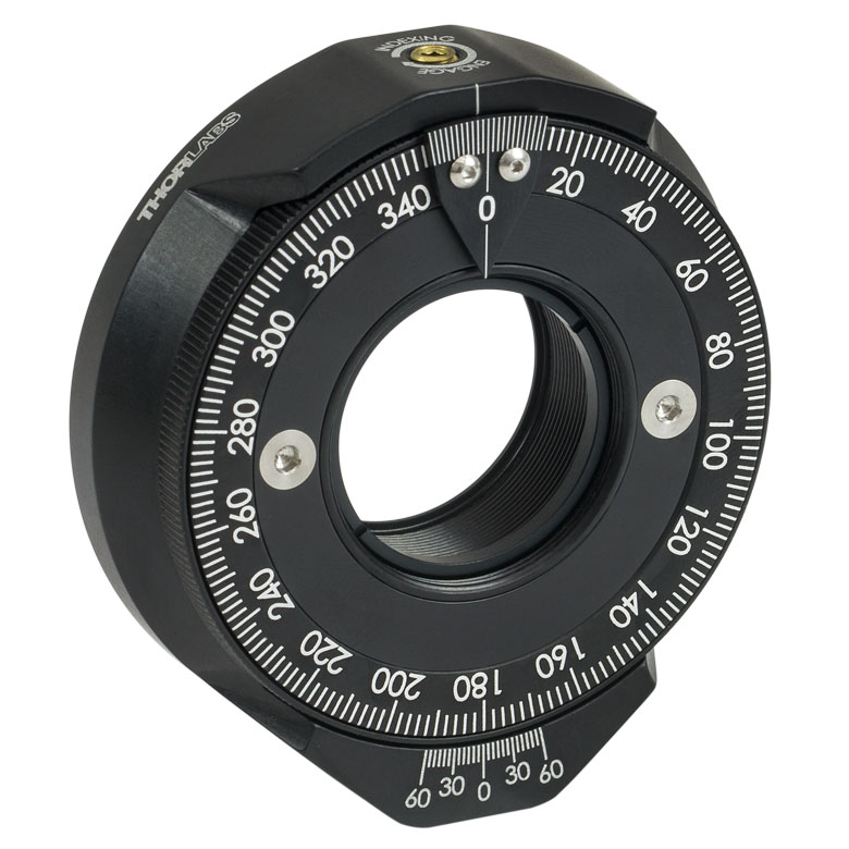
 Zoom
ZoomCharacterized by high-speed rotation and high-positional accuracy, the DDR100 stage is well-suited for applications where there is a need to rotate components at high speed within a cage or other system such as scanning, surface mapping and laser welding. Very precise, fine positioning and control is easily achieved through a combination of the stable closed-loop control system and a BBD series controller with associated MJC001 joystick option (available below).

 Zoom
Zoom- Adapter Plates for Mount Accessories
- Options Available with Keyway or Taps
- NR360SP4: 3 mm Keyway for Flexure Stage Accessories
- NR360SP9: 1/4"-20 Taps for Optomechanical Accessories
- Includes 8-32 (M4) Cap Screws for Mounting onto the DDR100(/M)

 Zoom
Zoom- Speed Adjustment for Fast or High Precision Moves
- Speed Dial for Sensitivity Adjustment
- Ergonomic Design
- High-Quality Machined Anodized Aluminum Casing
- High-Reliability Hall Effect Joystick
The MJC001 Joystick Console has been designed to provide intuitive, tactile, manual positioning of the DDR100 and other rotation stages. The console features a two-axis joystick for bidirectional control. In most applications, the default parameter settings saved within the controller allow the joystick to be used out-of-the-box, with no need for further setup, thereby negating the requirement to be connected to a host PC and allowing true remote operation.
The MJC001 is compatible with our Benchtop Brushless Controllers, Rack-Mounted Brushless Controller, and Stepper Motor Controllers. The joystick is shipped complete with cables for use with these controllers. If you intend to use the joystick with a legacy BBD10x series unit, please contact Tech Support for a compatible cable.