 Products Home
Specialty Optical Fiber Manufacturing

Please Wait
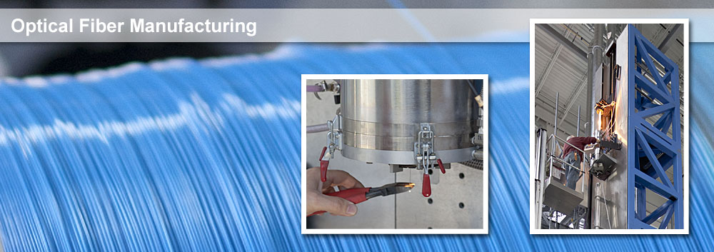
- State-of-the-Art Fiber Manufacturing Facility Produces our Extensive Catalog Offerings as well as Customer Specified Fibers
- Ability to Fabricate Passive and Active Fibers that Transmit in the UV through the MIR from Materials such as Silica, Fluoride, and Doped Glasses
- UV Curing Coating Capabilities for Materials Including Acrylate and Optical Polymers
- ITAR-Qualified Facility Located in Newton, NJ, USA, Experienced with University, Industrial, and Government Work
- Full In-House Design Team and Extensive Metrology Lab

Capabilities
- Specialize in Silica and Fluoride Glasses (Other Materials Available Upon Request)
- Transmission from the UV to the MIR: 200 nm - 5.5 μm
- Numerical Apertures: 0.10 to 0.48
- Fiber Core Sizes Range from 2 µm (Single Mode) to 1500 µm (Multimode)
- Custom Single Mode and Multimode Fluoride Glass Fibers
- Custom Multimode Silica Glass Fibers
- Active Fluoride Fibers with a Variety of Core and Cladding Geometries and Dopants such as Erbium, Thulium, and Holmium
- UV Coating Capabilities for Materials Including Acrylate and Optical Polymers
- Extrusion of Tefzel and Nylon Buffer Materials
- Flexible Manufacturing Setups and Schedules Allow for Prototyping as well as Volume Production
- Tensile Strength, Prooftesting, Static Fatigue, and Dynamic Fatigue Testing for All Fiber Types
- Attenuation, Spectral Attenuation, Bend Loss, and NA Testing in Our Metrology Lab
- Vertically Integrated Cabling Operation Provides a Full-Service Solution
Thorlabs' ITAR-certified fiber draw facility, located at our headquarters in Newton, NJ, fabricates specialty optical fiber for a variety of applications. In addition to manufacturing our extensive catalog offerings, this facility supports the flexible tower configurations and draw schedules required for fabricating custom fibers. Our engineering team has experience with designing and fabricating fibers for academic, industrial, and government applications.
The fiber drawn here is sold bare and is also made into connectorized patch cables or incorporated into many products in our ever-growing line of photonics equipment. This fiber will be sold to laboratories all over the world and will be used for everything from optogenetics to telecommunication applications.
We are able to accommodate requests for long fiber lengths resulting from one large, continuous fiber draw. However, the amount of fiber that can be drawn into a given spool will vary by production run. Please contact Tech Support with any specialty needs not covered by our standard offering. For more information about the draw process used at Thorlabs, please see the Preform Preparation and Draw Process tabs above.


Preform Preparation
Optical fiber production begins with a glass preform. The preform must be completely free of surface contaminants in order to produce high-quality fiber. We first attach a handle to the preform to allow the technician to move it without touching the preform itself. One handle is welded onto each end of the preform using an oxygen-hydrogen torch. The thermal expansion coefficient of the handle glass matches that of the preform glass to prevent the weld from separating as the temperature changes. These handles can be reused.
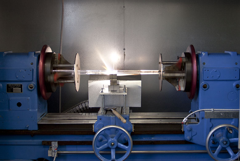
The handles are chucked into a lathe, suspending the preform over an oxygen-hydrogen burner. The preform is rotated as the burner slowly translates down its length, removing all surface contaminants. This process is called firepolishing. Firepolishing takes off the outermost layer of glass leaving a clean surface behind. This clean surface ensures the resulting fiber has the highest strength possible.
Once the firepolishing is complete, one of the two handles is removed leaving a pointed "drop" end. The preform is fed far enough into the furnace that, when a high enough temperature is reached, the drop end exits the furnace and initates the draw. The handle that remains will support the preform on the tower.
Click on the Draw Process tab for information about the next steps in the draw process.
Click on the Fiber Draw Tower shown below for further details.

Preform

Optical fiber production begins with a preform. The core/clad ratio of the preform is maintained during the draw process. The resulting optical fiber has this same core/clad ratio.
The silica fiber production facility at Thorlabs uses cylindrical silica preforms. Silica is commonly used to make optical fiber because it has good transmission over a wide range of wavelengths and low absorption and scattering losses (~0.2 dB/km). Silica is also highly resistant to both mechanical and optical damage. It can withstand pulling and bending as well as amplified laser pulses.
Thorlabs manufactures optical fiber in one of two ways: drawing a preform containing a glass core and a glass clad or drawing a pure silica rod and coating the resulting fiber with an optical polymer as the cladding.
The preform is prepared for draw on the glass-working lathe. Please see the Preform Preparation tab for more information about glass working and firepolishing. The handle end is chucked, or loaded, into the top-feed unit located at the top of the tower.
Furnace

The top-feed unit lowers the preform into the furnace, and the heating process begins. This inline furnace has a graphite element that surrounds, but does not touch, the preform. The graphite allows the heat to be evenly distributed around the glass cylinder. High-purity, oxygen-free Argon gas is cycled through the furnace to protect the graphite element at high temperatures.
The furnace slowly heats up the preform. As the temperature rises, the preform will start to glow. This bright orange glow is caused by the heat of the furnace and will scatter at the weld between the handle and the preform. The preform transmits light similarly to the optical fiber it will become.
Once the furnace reaches about 2000 °C, the drop end of the preform begins to fall under gravity through the hole in the bottom of the furnace. The drop end is what remains after a quartz handle has been removed after firepolishing.
A technician cuts the drop end off the glass flow and begins to pull the newly drawn fiber out of the furnace. He tapes a small weight to the end of the glass and threads it through the rest of the apparatuses along the length of the tower and into the capstan puller. This process can be seen in the photo gallery below.
Diameter Measurement

The fiber travels 36 feet from the furnace to the capstan. The speed that the fiber is drawn is inversely proportional to the desired diameter of the fiber: the larger the diameter, the slower the draw speed. The fiber passes through three diameter monitors: one directly after the furnace measuring the bare fiber diameter, one after it is coated, and one after the buffer jacket is applied. These monitors are connected to the tower control system. The bare glass diameter is used to control the capstan speed and maintain the desired fiber diameter.
Cooling Chamber

After coming out of the furnace, the fiber travels through a cooling chamber. Chilled water and helium gas are cycled through the 150 cm long cylinder, keeping it at an internal temperature of 12 °C. The fiber is cooled to room temperature as it passes through this chamber. Fiber needs to be at room temperature for proper coating application.
Coating

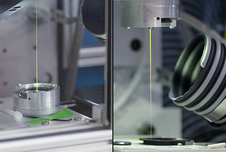
Once the fiber is thin enough, the technician cuts off the bottom portion of unusable fiber and feeds it through the coating cup. Thorlabs coats its fiber with a variety of coatings including TECS, acrylate, and polyimide. TECS is an industry-leading hard optical polymer cladding material that was developed by 3M™ and is now offered exclusively by Thorlabs. A coating layer is applied as the fiber is passed through a coating cup. The thickness of the coating is controlled by the inner diameter of the carbide dies in the coating cup.
The coating goes on the fiber wet and is hardened in the UV curing units located just below the coating cup. This coating protects the surface of the optical fiber, maintaing its intrinsic strength.
Final Steps

The capstan at the bottom of the fiber tower provides the pulling action that forms the fiber from the preform during the draw. After exiting the capstan, the fiber is pulled through an extruder where a Tefzel, or nylon, buffer is applied. The application of the extruded buffer can be seen in the picture to the left. A wide variety of buffer colors are available.
The Draw Process


Testing and Characterization Capabilities
- Spectral Attenuation Measurement
- UV / Visible / NIR / MIR Wavelength Range
- SM or MM Fiber and Bulk Glass
- SM Fiber Cutoff Wavelength Measurement
- Fiber NA Measurement
- Fiber Glass / Coating Geometry Measurement with Sub-µm Accuracy
- MIR High-Power Screening for MM Fibers
- Fiber Tensile Strength Testing
- Defect / Break Analysis
- Degree of Cure Testing for Fiber Coatings
Request testing for Thorlabs or third-party fibers by contacting Tech Support.
Capabilities
- Zirconium Fluoride (ZrF4) and Indium Fluoride (InF3) Fiber Production
- Transmission in the Mid-IR Region up to 5.5 µm
- Flexible Manufacturing Setups and Schedules Allow for Prototyping as well as Catalog Production
- Custom Fiber Options:
- Different Cross-Sectional Shapes, Such as Hexagonal, Square, and D-Shaped
- Single Mode Fiber with Core Diameters <20 µm
- Multimode Fiber with Core Diameters >20 µm
- NAs Ranging from 0.10 to 0.35
Thorlabs' optical fiber draw facility produces and draws zirconium fluoride (ZrF4) and indium fluoride (InF3) fibers in addition to drawing silica fiber. ZrF4 and InF3 fibers feature high transmission over the 300 nm - 4.5 µm spectral range or 300 nm - 5.5 µm spectral range, respectively, with no material absorption peaks, excellent mechanical strength, and good environmental stability.
Fluoride fibers are ideal for transmission in the mid-IR wavelength range. Low attenuation in the MIR wavelength range is aided by an extremely low hydroxyl ion (OH) content. Fluoride fibers also have a lower refractive index and lower chromatic dispersion when compared to other fibers that offer transmission in the mid-IR range. Thorlabs' fluoride fibers are ideal for use in applications including mid-IR spectroscopy, fiber optic sensors, imaging, and fiber lasers.
Fluoride Preform Manufacturing and Fiber Draw Process
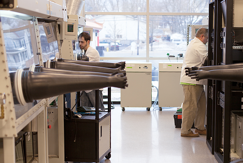
Thorlabs' fluoride fibers are fabricated using a technique that provides world-class purity, dimensional control, and strength. The glass components are combined and melted in the controlled environment of a glove box for purity. Once the glass is melted, it is poured into the preform mold and cooled.
After preparation, the preform is loaded into the down-feed unit at the top of the tower and drawn into fiber. Fluoride glass fiber is drawn using preform techniques similar to that used for silica fibers (see the Draw Process tab for details). This technique is well developed and has proven to be very effective in controlling fiber parameters, such as fiber diameter, concentricity, and the refractive index profile. The drawing temperature range of fluoride glasses is lower than that of silica, significantly reducing the cooling time. Thus, our fluoride fiber draw tower is much shorter than our silica fiber towers. The diagram below to the right details the components on our fluoride fiber draw tower.
Thorlabs' team of mid-IR fiber researchers and engineers has many years of experience in fluoride glass research and development, production, and fiber draw. Our team is divided into two groups: one dedicated to production of catalog items and the second devoted to research and development and custom fiber manufacturing. Their knowledge and expertise, as well as flexible tower configurations and draw schedules, allow us to produce both catalog items as well as custom orders. For details on our custom fluoride fiber capabilities, please contact Tech Support.
Fluoride Fiber Characterization and Testing
Thorlabs has a team dedicated to the testing and characterization of our fiber products. We precisely measure the properties of each drawn fiber to ensure that it meets our high standards of quality. Extensive testing also provides feedback for our fiber draw team, enabling tight control of each step in the manufacturing process. Customers can request custom testing of any Thorlabs-manufactured fiber, which is then provided with the shipped fiber. Testing of third-party fiber samples provided by customers is also available upon request. Available tests and services are provided in the list to the right; please contact Tech Support with inquiries.

Schematic of Our Mid-IR Fiber Draw Tower
Thorlabs' Mid-IR Fiber Capabilities


Kaitlin Hoffmann |
"Thorlabs' Fiber Business Unit has the unique advantage of drawing optical fiber to our own specifications so that it is precisely suited for integration into high-end finished assemblies. Our knowledge and expertise not only provide the highest quality products for our customers but also allow us to easily customize anything from bare optical fibers to fully integrated assemblies." |

With three fiber draw towers, an in-house R&D team, and on-site metrology and testing, our ITAR-qualified fiber facility is built to accommodate the flexible tower configurations and draw schedules required for volume production on short notice. It is accustomed to the on-time fulfillment of academic, industrial, and government contracts and offers same-day shipping for patch cables with custom lengths and connectors.
We are collaborating with university customers to widen our industry-leading selection of optogenetics equipment, and we routinely accept orders for modifications of Thorlabs' catalog products.


| Posted Comments: | |
Ashok Chopra
(posted 2020-09-30 08:01:13.533) is there a Water Bath required anywhere in the Drawing Tower, perhaps for maintaining Coating Temperature OR for stabilising the extruded Buffer cover ? asundararaj
(posted 2020-10-06 07:28:53.0) Thank you for contacting Thorlabs. In our Fiber tower, there is a cooling chamber that the fiber goes through after it is pulled and before coating is applied, but there isn't a cooling process during or after the application of the coating. You can find more information on this in this link, I have contacted you directly to discuss this further - https://www.thorlabs.com/newgrouppage9.cfm?objectgroup_id=6832&tabname=Draw%20Process Jordan Adams
(posted 2019-12-13 12:58:33.937) Would like to order custom fiber. We want a double clad ytterbium fiber that is tapered (decreasing). YLohia
(posted 2019-12-13 02:34:13.0) Thank you for contacting Thorlabs. Custom items can be requested by emailing techsupport@thorlabs.com. We have not offered such a fiber previously, but I have reached out to you directly to discuss the possibility of offering this. user
(posted 2019-07-08 04:38:37.77) Hello, what is the minimal quantity required for manufacturing fiber with custom rare earth doping concentration? Thanks in advance. YLohia
(posted 2019-07-08 10:40:23.0) Hello, thank you for your interest in our products. Please reach out to us at techsupport@thorlabs.com with your inquiry since we do not have your contact info for further communications. k.nasiri
(posted 2018-07-14 14:09:00.74) Dears,
I was reading below feedback but I can not sure about it.
Would you please inform me that are you provide and implementing a full package of optical fiber manufacturing tower line with engineer training and other needs or not?
Regards
Nassiri YLohia
(posted 2018-07-16 08:41:35.0) Hello Nassiri, thank you for contacting Thorlabs. Unfortunately, setting up a fiber draw tower is beyond the scope of the type of assistance that Thorlabs can provide. asha
(posted 2017-08-19 13:28:54.913) I need to install a drawing tower in my lab. What is the basic model you can provide. Or can you provide furnace and a preform holder used in a drawing tower.
Thanks tfrisch
(posted 2017-08-28 10:54:22.0) Hello, thank you for contacting Thorlabs. It looks like you are already in contact with Tech support, but unfortunately we are not able to offer components that could be used to make a fiber draw tower. t-bach
(posted 2015-12-18 10:46:20.353) Hello,
I have a question regarding the supply possibility of manufacturing a special fiber. Please reply to this comment, so that we can continue to talk.
Thank you jlow
(posted 2015-12-18 08:58:38.0) Response from Jeremy at Thorlabs: We will contact you directly about the details on making the special fiber. emichael
(posted 2015-11-05 13:14:27.81) Dear Ladies and Gentlemen,
I wonder if Thorlabs can make photonic crystal fiber from a custom material using your facility you show in the video.
I have in mind for example CS 3-68 glass because of its record
nonlinearity. If so, what would it cost approximately?
Kind regards, Ernest Michael besembeson
(posted 2015-11-05 01:40:45.0) Response from Bweh at Thorlabs USA: Thanks for contacting Thorlabs. At this time we don't manufacture these photonics crystal fiber in-house. You may want to contact NKT Photonics to discuss your requirements. yichang
(posted 2014-05-22 21:39:09.663) I am looking for a circulator with wavelength in the UV-Visible-NIR range (350nm-1000nm). Is it possible to manufact? Any minimal quantity is required? Please reply.
Thanks
Yin Chang besembeson
(posted 2014-06-05 07:17:40.0) A response from Bweh E at Thorlabs Newton-USA: There are few things that limit the type of fiber circulator that can be made, most stringent is the fiber itself. Circulators need to work with single mode fiber and the SM fiber ranges generally fall into the following regions: 320 – 430nm, 400 – 680nm, 630 – 860nm, 780 – 970nm, 980 – 1060nm, 1260 – 1625nm. Within those regions we have Faraday rotator elements that are the basic component in a circulator. The Faraday elements have a general range of about +/- 10nm so we offer models that are centered at the more common wavelengths: 660nm, 780nm, 850nm, 1030nm, 1064nm, 1310nm, 1550nm, and 2000nm. We do not offer models below 660nm because the combination of small core size and higher loss in the Faraday material are very difficult to overcome. akhalifa
(posted 2013-09-05 15:30:36.873) Hello,
Just one small question regarding your optical fiber draw tower. Do you measure the fiber tension while drawing ? There was one small device, which was not explained in the description of the draw tower process that located below the second curing unit and just above the second diameter meter. Does this device measure the tension ? The reason behind my question is that we are developing a new tension measuring method and we want to know what is being used for this purpose.
Best regards
Ahmed Khalifa
Institut für Mikroelektronik,
Mikromechanik und Mikrooptik (I3M)
Hochschule Bremen
akhalifa@stud.hs-bremen.de jlow
(posted 2013-09-05 11:03:00.0) Response from Jeremy at Thorlabs: We do monitor the fiber tension during the drawing of our smaller diameter fibers. We will contact you directly regarding this. |