 Products Home / Optomechanical Components / Optical Rails / 25 mm Optical Rails / Optical Enclosure Accessories
Optical Enclosure Accessories

- Anodized Aluminum and High-Strength Plastic Cubes for Corners
- Black Hardboard and Aluminum Enclosure Panels
- Hinge and Backstop for Easy-to-Use Lids
- Cover Plate Protects Rail End
XE25H
Hinge for Lids or
Other Openings
XE25W3
Quick-Install Corner
XE25LS
Backstop
XE25C
Cover Plate
TB4
Black Hardboard
RM1S
Slotted to Accept Hardboard
XE25DK1
Sliding Door Kit
(Not to Scale)
LPCE9
Laser Safety Fabric Panel


Please Wait
| XE25 25 mm Construction Rail Accessories | ||||
|---|---|---|---|---|
 |
 |
 |
 |
 |
| Rails | Cubes and Brackets |
Breadboard Mounting |
Rail Joiners | Channel Insert |
 |
 |
 |
 |
|
| Construction Tools |
T-Nuts and Screws |
Enclosures | Enclosure Accessories |
|

Click for Details
Side view of XE25C11 and AEPU1 enclosure utility panel.
Features
- Construction Cubes for Rigid Corners and Joints
- Right-Angle Brackets Reinforce Corners
- Enclosure Panels
- Black Hardboard Panels are Lightweight and Block Unwanted Light
- Durable Aluminum Panels with Blank Connection Panels
- Laser Safety Fabric Panels Certified to EN Specifications
- Kit for Assembly of Sliding Doors for Existing Enclosures
- Hinge for Constructing Lids that Smoothly Open and Close
- Attachable Handles Allow Easy Movement
- Backstops Hold Enclosure Lids Open
- Cover Plate Hides Exposed Rail Ends
Thorlabs' add-ons for 25 mm rail optical enclosures aid in building complex structures that are sturdy and easy to use. We offer construction cubes of either high-strength plastic or anodized aluminum for forming corners of up to three rails and a bracket that reinforces right-angle connections. Our black hardboard and posterboard panels block stray light and can easily be cut to size. We also offer a kit for the addition of sliding doors to an existing optical enclosure such as the XE25C9(/M). Additionally, our hinges and backstops help construct convenient enclosure openings. Our non-flammable, black-anodized aluminum enclosure utility panels offer superior durability to our black hardboard panels, while our flame-retardant laser safety fabric panels provide a flexible alternative. Thorlabs also manufactures a cover plate designed to shield a rail end.
Thorlabs' accessories for assemblies made of 25 mm rails include corner cubes and brackets, T-Nuts, low-profile channel screws, breadboard mounting accessories, rail joiners, and a channel insert. In addition, we offer optical enclosures, enclosure accessories, and do-it-yourself tools like taps, tap guides, and drill guides for home-built XE25-based constructions.

XE25 Construction Techniques
Thorlabs' XE25 rails and components are the building blocks for many types of modular systems, including custom enclosures. For the most demanding applications, Thorlabs recommends the "direct connection" technique for forming right angles with rails, detailed here. All the construction parts shown in this tutorial are available on our XE25 Construction Tools page.
Step 1: Drill Side Holes


A Ø4.6 mm hole in the end of one rail, as shown in the picture to the right, is needed to provide access for a 1/8" (4 mm) balldriver.
For this step, you will need the T119873 Ø4.6 mm Drill Bit, the XE25DG Drill Guide, a hand drill or drill press, and a vise such as the TMV2.
The XE25DG drill guide is secured to the rail using the locking screw on top. A guide hole for the drill bit will be located 12.5 mm from the end of the rail. Now a hole can be drilled into the rail as shown in the figure to the left.
If your application requires a "three-way corner," such as that shown at the top of the page, you will have to drill a second hole in the rail at a 90° angle relative to the first hole.
Step 2: Tap the Center Hole, If Necessary

All stock and custom-length anodized XE25 rails have a 1/4"-20 (M6) tapped hole in the end of the rail. If you have cut a standard XE25 rail, or are using the XE25RL2 Raw Extrusion, you will need to tap a hole into the end of the rail.
For this step, you will need the 71598 1/4"-20 Tap (or the 71498 M6 Tap), the XE25TG Tap Guide, and the TW25 Hand Tap Wrench.
Fix the tap inside the tap wrench. Place the tap guide block over the end of the rail. The hole in the top of the guide will keep the tap square with the hole and minimize the chance of misthreading. Turn the tap to thread the hole.
Step 3: Attach Low-Profile Channel Screw

For this step, you will need a SH25LP38 1/4"-20-threaded (SH6M10LP M6-threaded) Low-Profile Channel Screw and a 1/8" (4 mm) balldriver.
Insert the screw into the threaded hole in the end of the rail, and tighten down partway with the balldriver. If you are making a three-way connection, you will need to thread another channel screw into the end of a second rail.
Step 4: Join the Rails


Slide the head of the channel screw into the channel of the rail with the drilled holes, so that the hex head lines up with the hole. Insert the balldriver into the hole, and tighten the channel screw. If making a three-way connection, repeat this process with the third rail, as shown in the figure to the right.
For increased stability, the corners may be reinforced with the XE25A90 Right-Angle Bracket.
525 mm (L x W x H) enclosure with black hardboard panels. The parts needed for this custom enclosure are provided in the tables below.
Design a Custom Enclosure Using Thorlabs Components
With our vast selection of enclosure components, building your own DIY optical enclosure is simple. All our optical enclosure components, from panels to optical rails and corner cubes, can be purchased separately and customized to a size suitable for your application. For example, simple enclosures can be constructed to be as small as 1' x 1' x 1' (300 mm x 300 mm x 300 mm), whereas much larger enclosures are possible and might include hinged doors for easy access to an experiment. Enclosure components are designed to work together seamlessly, reducing the amount of time required during assembly.
Any side or dimension of the enclosure can be modified to suit the requirements of your application. The black hardboard enclosure panels can be cut to the appropriate size or drilled to accommodate integrating optomechanical components, like lens tubes. Alternatively, black-anodized aluminum panels are available with pre-drilled slots, for fiber and electrical panels, and an SM1-threaded (1.035"-40) through hole.
Should you choose not to build your own DIY enclosure, we welcome the opportunity to work with you to provide a custom enclosure that meets your specific requirements. Customizable options include enclosure dimensions, like panel sizes and optical rails; panel material, like black hardboard or black-anodized aluminum; and number and configuration of doors. We will ensure the proper fit and function of the customized components. Once the custom enclosure meets specification, we will ship the components for customer assembly. Please note that aluminum breadboards are not included with our custom enclosures and that enclosures will need to be assembled by the customer.
If you would like consultation regarding whether to place a custom order or which components you need to purchase in order to assemble your own DIY optical enclosure, please contact Tech Support.
Custom Enclosure Example
This section details how to construct a two-door enclosure with black hardboard panels, which is shown completely assembled in the bottom-right image. Watch the video above for step-by-step instructions on how to assemble this particular enclosure. The size of this enclosure is 1200 mm x 600 mm x 525 mm (L x W x H). Refer to the tables below for a complete parts list. The enclosure was constructed from metric components, but it can also be constructed using the imperial equivalent components.

Click for Details
Custom enclosures can be built using our 25 mm rails and accessories. This two-door enclosure was constructed entirely from stock items. The video above provides step-by-step instructions on how to assemble this enclosure.

Click to Enlarge
Two TB4 hardboards (cut to the required height) can be taped together using T743-2.0 Black Masking Tape to form the back panel of the enclosure.
This enclosure was assembled on a 600 mm x 1200 mm aluminum breadboard (24" x 48" for imperial components), though other breadboard sizes are possible. The left and right doors are 500 mm and 600 mm (20" and 24") wide, respectively. Each door can be opened separately, allowing access to the breadboard inside the enclosure. We recommend building the doors and frame of the enclosure separately and then assembling them to complete the enclosure. The rails used in the doors and frame are connected via construction cubes with slotted corners, which help to prevent light leakage at the corners of the enclosure, and are secured using low-profile channel screws. Alternatively, for a faster solution, our quick corner cubes can be used. Our TB4 hardboard, which constitute the panels of the enclosure, can be cut to size using a utility knife; these pieces fit directly into the slots of the 25 mm rails and the counterbores of the cubes. The back panel is formed using two pieces of hardboard cut to the desired length and height and taped together using T743-2.0 Black Masking Tape (see the image to the right). Note that, for the imperial enclosure, black masking tape will also be needed to connect the 24" x 24" panels together along the sides and back of the enclosure.
A 25 mm rail is installed along the top of the enclosure to mount the doors and door hinges. This rail is attached by drilling through the top two frame rails; see the video above for details. For details on drilling and tapping a hole into the top frame rails for precise placement of the support rail, see the Construction Methods tab above.
The height of the enclosure can easily be customized to fit any application. For best results when adding doors to your enclosure, the total door height with connection cubes should match the enclosure height minus the bottom rails; otherwise, the door will overlap with the bottom rail. We recommend using 500 mm (20") and 525 mm (21") long rails for the door and enclosure, respectively.
For applications requiring a light-tight enclosure, our BFP1 black flocked self-adhesive paper can be used to seal gaps in the hinges of the enclosure.
| Posted Comments: | |
| No Comments Posted |

 Zoom
Zoom
Click to Enlarge
Three-Way 25 mm Rail Junction Using an RM1G Construction Cube

Click to Enlarge
RM1S Slotted Cube Securing a Hardboard Enclosure Wall
- Hold up to Three Rails at Right Angles
- RM1G: Counterbored on Three Sides
- RM1S: Counterbored on Three Sides and Slotted to Accommodate Enclosure Walls
- One-Piece Aluminum Construction for Excellent Rigidity
- Parallel and Perpendicular to Within 0.002" (0.05 mm)
- For Use with Low-Profile Channel Screws
These Construction Cubes contain three 1/4" (M6) counterbores on adjacent faces. They can be connected to up to three rails by tightening our Low-Profile Channel Screws (sold at the bottom of this page) through the counterbores, as shown in the images to the right. In addition, the RM1S cube has slotted corners to accept posterboard and hardboard walls for the construction of light-tight optical enclosures. Since both these cubes are machined from a single block of aluminum, they are ideal for constructions that need to be as sturdy as possible.

 Zoom
Zoom
Click to Enlarge
Three-Way 25 mm Rail Junction Using an XE25W3 Quick Corner Cube
- Holds up to Three Rails at Right Angles
- Made from High-Strength Reinforced Plastic
- For Use with Low-Profile Channel Screws
The prongs on the faces of an XE25W3 Quick Corner Cube are positioned to fit into the four alignment holes on the end of a 25 mm rail. Because the prongs and the alignment holes form a tight fit, it may be difficult to insert the corner cube by hand. We therefore recommend using our Low-Profile Channel Screws (sold at the bottom of this page) to fasten the corner cube to the rail, as shown in the image and the animation to the right.
Although these corner cubes provide excellent results when building enclosures, they are not recommended in cases where rails are being used to support optomechanics. In these situations, please use the RM1G Construction Cube shown above, or consider the techniques shown in the Construction Methods tab.

 Zoom
Zoom
Click to Enlarge
Reinforced Corner

Click to Enlarge
Enclosure Bolted to Optical Table
- Brace 25 mm Rail Corners or Mount Rails Vertically
- One-Piece Aluminum Construction for Excellent Rigidity
- For Use with 1/4"-20 (M6) Cap Screws
The AB90H and XE25A90 Right-Angle Brackets can be used to fasten 25 mm rails to each other using a T-Nut (not included) or to an optical table. Both intended for use with 1/4"-20 (M6) cap screws and washers, the AB90H has a total of two 1/4" wide slots of lengths of 1" (25.4 mm) and 0.5" (12.7 mm), allowing for additional flexibility in positioning the rails on a breadboard, while the XE25A90 has two counterbored holes.
These brackets are ideal for fastening our optical enclosures to an optical table or breadboard.

 Zoom
Zoom

Click to Enlarge
Enclosure with TB4 Panels
- Blocks Stray or Unwanted Light
- Easily Shaped with a Utility Knife
- TB5: 1/16" (1.6 mm) Thick, Solid Cardboard Panel
- TB4: 3/16" (4.76 mm) Thick, Plastic-Coated Cardboard Panel with Foam Core
Thorlabs' black panels are an essential component of light-tight enclosures. Our TB5 Black Posterboard is 1/16" (1.6 mm) thick and ships in packages of five 20" x 30" (50.8 cm x 76.2 cm) panels. Simply score the panel with a utility knife and bend to form a light-tight corner.
In contrast, our TB4 Black Hardboard is 3/16" (4.76 mm) thick and ships in packages of three 24" x 24" (61.0 cm x 61.0 cm) panels. The increased thickness provides enhanced acoustic absorption, while the foam core (pictured to the right) helps it remain lightweight. We recommend using our 2" wide black masking tape for corners and other joints to eliminate the passage of light through those areas. This is the same hardboard used in our preconfigured optical enclosures.
Upon request, we can offer the TB4 hardboard in custom sizes up to 48" x 48" (121.9 cm x 121.9 cm) to customers in North America, or up to 44" x 32" (111.8 cm x 81.3 cm) elsewhere. Please contact Technical Support for a quote. Thorlabs also offers a comprehensive selection of blackout materials.

 Zoom
Zoom| Damage Threshold Specificationsa | |
|---|---|
| Type | Damage Threshold |
| Pulsed | 0.50 J/cm2 (532 nm, 10 ns, 10 Hz, Ø0.504 mm, 200 shots) 0.90 J/cm2 (1064 nm, 10 ns, 10 Hz, Ø1.00 mm, 200 shots) |
| CW | 23.6 W/cm (532 nm, Ø1.00 mm, 60 s exposure) |

Click to Enlarge
AEPU1 Being Inserted in an Aluminum Enclosure
- Anodized Aluminum For Durability
- Four Blank Connection Panels and One SM1-Threaded Through Hole
- Eliminates Need to Drill Holes for Connectors
- Rubber Anti-Vibration Dampeners Increase Stability
- Available in 15" x 12" (375 mm x 300 mm) or 9" x 12" (225 mm x 300 mm) Sizes
- 0.13" (3.2 mm) Thick
These aluminum enclosure utility panels feature four RBX-BLK1F blank connection panels and one SM1-threaded (1.035"-40) through hole covered by a removable SM1CP2M end cap. The blank connection panels can be removed for easy installation of our fiber or electrical connection panels. The SM1-threaded hole allows for a range of SM1-compatible components, like our lens tubes, to be installed. Designed to be used in an optical enclosure, each utility panel includes six rubber anti-vibration dampeners to increase durability and stability, eliminating rattling when the enclosure is moved.
These enclosure panels are designed to be used in our line of optical enclosures. The AEPU2(/M) enclosure panel is compatible with our XE25C7(/M) and XE25C8(/M) black hardboard enclosures, while the AEPU1(/M) enclosure panel is compatible with the XE25C9(/M) and XE25C9D(/M) black hardboard enclosures, as well as the XE25C10(/M) and XE25C10D(/M) Plexiglass enclosures. Note the AEPU1(/M) is already included with our XE25C11(/M) aluminum enclosure.
These aluminum enclosure panels are offered in custom sizes and designs. Please send all inquiries to Tech Support.

 Zoom
Zoom Click to Enlarge
Engraved dots indicate the widened channels.
- Kit for Constructing Sliding Doors Compatible with 25 mm Rail Optical Enclosures
- 21" x 12" (525 mm x 300 mm) Rail Assembly
- Doors Made of TB4 Hardboard to Block Stray or Unwanted Light
- Some Assembly Required
- Compatible with the XE25C9(/M) Optical Enclosure
The XE25DK1(/M) Sliding Door Kit allows for the integration of sliding doors or a barrier into an existing optical enclosure. This kit uses 21" (525 mm) long and 12" (300 mm) long rails, resulting in an overall 23" x 13" (584 mm x 325 mm) frame. The frame is shipped with the rails assembled; the door panels, handles, and door guide must be added during final assembly. Holes are pre-drilled for quick installation of the handles.
Please note that the rails and cubes included in this kit are not identical to our stock items. Each rail includes a widened channel over twice the thickness of TB4 panels to allow for each panel to slide over the other. The widened rail channels are indicated with engravings, as seen in the image to the right. For a complete enclosure assembly that includes the doors from this kit, please see the XE25C9D(/M) enclosure.

 Zoom
Zoom| Fabric Panel Item # | Dimensions | Compatible Enclosures |
|---|---|---|
| LPCE9 | 10.96" x 12.99" | XE25C7 XE25C8 |
| LPCE15 | 16.97" x 12.99" | XE25C7 XE25C9 |
| LPCE21 | 22.97" x 12.99" | XE25C8 XE25C9 |
| LPCE225/M | 275.0 x 325.0 mm | XE25C7/M XE25C8/M |
| LPCE375/M | 425.0 x 325.0 mm | XE25C7/M XE25C9/M |
| LPCE525/M | 575.0 x 325.0 mm | XE25C8/M XE25C9/M |

Click to Enlarge
LPCE21 Panel Used to Replace One Hardboard Side of an Optical Enclosure. The thumbscrews can be easily removed in order to access the inside of the enclosure.
- Attach to 25 mm Rails for Optical Enclosures
- Flame Retardant
- Certified to EN 12254: 2010(E) (See Disclaimer Below)
- For Custom Sizes, Contact Tech Support
- Fasteners Sold Separately Below
These laser safety fabric panels are designed for the sides of our optical enclosures. Alternatively, the panels can be attached to custom-built enclosures using 25 mm rails. The table to the right shows compatible enclosures for each fabric panel.
All imperial panels are 12.99" tall and designed for an enclosure using vertical XE25L12 rails. All metric panels are 325.0 mm tall and designed for an enclosure using vertical XE25L300/M rails.
The fabric panels can be attached to the 25 mm rails using the LPCEF(/M) fasteners sold separately below.
*DISCLAIMER
This laser safety fabric has been tested by a third party using EN specifications; see the Certifications tab of the full web presentation for details. Due to manufacturing variances, mechanical wear, and laser damage, Thorlabs assumes no responsibility for laser material failure. Please consult your local laser safety specialist before purchasing to ensure that the fabric is suitable for your application. To minimize risk, inspect the material before each use and ensure that it is in excellent condition.

 Zoom
Zoom- Attach Laser Safety Fabric Panels to 25 mm Rail Channels
- Each LPCEF(/M) Kit Includes:
- Seven 8-32 (M4 x 0.7) Thumbscrews
- Seven 8-32 (M4 x 0.7) T-Nuts
- Seven 8-32 (M4 x 0.7) Setscrews
- Replacement 8-32 (M4 x 0.7) Thumbscrews Available [Item # LPCET(/M)]
The LPCEF(/M) fastener kit contains seven sets of thumbscrews, T-nuts, and setscrews. One fastener kit is enough to affix one laser safety fabric panel to the side of a compatible enclosure. Please see the manual for instructions.
The setscrews can be tightened using a 5/64" (2.0 mm) hex key or balldriver, while the thumbscrews do not have a hex socket.
Replacement thumbscrews for the fastener kit are also available in packs of 10.

 Zoom
Zoom
Click to Enlarge

Click to Enlarge
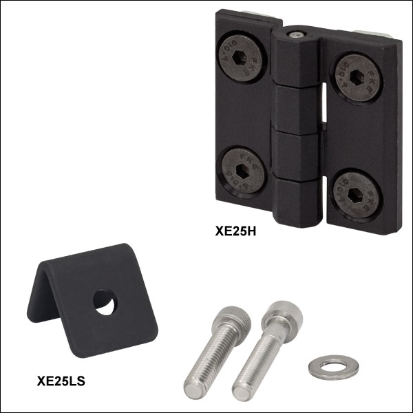
Back of XE25H Hinge
- Build Lids that Swing Open and Closed
- Lid Stops Allow Hands-Free Operation in Confined Spaces
- Installed Using Rail Channels
The XE25H Hinge is a high-strength, molded plastic hinge that creates a cover that smoothly opens and closes. It is held in the rail channel by four low-profile channel screws and four T-Nuts (all included) that fasten with a 3 mm balldriver. Please note that the closed hinge leaves a gap between the two rails to which it is attached, resulting in an opening that is not light tight without further modification.
The XE25LS Lid Stop is an anodized aluminum backstop that limits the travel of a lid to a 120° arc, holding the lid open and allowing hands-free operation inside the enclosure. It is ideal for setups with limited space or other situations where a fully open lid is not desirable. The XE25LS attaches to the rail channel using a T-Nut (not included) and is packaged with a 1/4"-20 cap screw, an M6 cap screw, and a washer.

 Zoom
Zoom
Click for Details
Breadboard Handle Mounted onto a 25 mm Rail at the Base of a Custom Optical Enclosure
- Attach Handles to Rails
- Easily Open and Close Optical Enclosures
BBH1 Handles can be attached to optical enclosure rails for simplified transport and movement. As shown to the right, handles can be placed on an enclosure door, allowing easy opening and closing. These polymer handles are reinforced with glass fiber and are rated up to 250 kg (550 lbs) when properly installed. The two through holes allow the handles to be attached to rails using T-Nuts and standard 1/4"-20 or M6 cap screws (each sold separately). These handles can also be directly attached to breadboards, simplifying their removal from frames and ScienceDesks.

 Zoom
Zoom
Click to Enlarge
- Hide Exposed Rail Ends
- Beveled Corners Match Beveled Edges of 25 mm Rail
These 1 mm thick cover plates are designed to hide an exposed extrusion end. To maintain a minimal physical profile, we recommend the use of Low-Profile Channel Screws to hold the cover plate in place. These screws are sold below.

 Zoom
Zoom| Item # | Threading | Thread Length | Hex | Head Height | Quantity | Material |
|---|---|---|---|---|---|---|
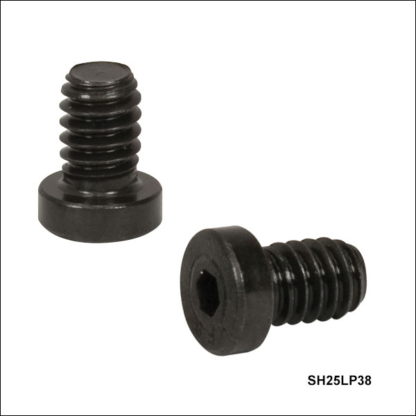
| SH25LP38 | 1/4"-20 | 0.38" (9.7 mm) | 1/8" | 0.13" (3.2 mm) | 100 | Steel, Black Oxide Finish |
| SH25LP63 | 0.63" (15.9 mm) | 50 | ||||
| SH6M8LP | M6 x 1.0 | 8 mm (0.31") | 4 mm | 4 mm (0.16") | 50 | |
| SH6M10LP | 10 mm (0.39") | 100 | ||||
| SH6M16LP | 16 mm (0.63") | 50 |

Click to Enlarge
Low-Profile Screw in RM1G Construction Cube

Click to Enlarge
Standard Cap Screw in RM1G Construction Cube
Our Low-Profile Channel Screws have a reduced cap head height relative to standard screws, permitting them to be used in tight spaces. In particular, they are recommended when neighboring screws are at a right angle and in close proximity, as in our XE25W3 Corner Cube or RM1G and RM1S Construction Cubes.
Shown to the right are a standard cap screw and a low-profile channel screw installed in an RM1G cube. The low-profile screw's shortened cap height prevents neighboring screws from interfering with each other.
The head of each screw also fits into XE rail channels for alternate construction methods, as outlined here.