 Products Home / Incoherent Sources / Superluminescent Diodes (SLDs) / NIR Superluminescent Diodes (SLDs)
NIR Superluminescent Diodes (SLDs)

- Broadband Emission Wavelengths from 810 nm to 1550 nm
- Low Ripple
- Butterfly Package
SLD1325
1325 nm SLD, >100 nm Bandwidth
Application Idea
SLD1550S-A2
Superluminescent Diode
Mounted in a CLD1015 Compact
Laser Diode Driver with TEC


Please Wait
| Recommended Controller / Mount Options | |||
|---|---|---|---|
| Item # | Mount | Diode Driver | TEC Controller |
| CLD1015 | |||
| LM14S2 | - | - | |
| ITC4000 Series | Use with LM14S2 Mount | ||
| LDC200 Series | Use with LM14S2 Mount | - | |
| TED200C | Use with LM14S2 Mount | - | |
Features
- Center Wavelengths from 810 nm to 1550 nm
- Typical 3 dB Bandwidths Ranging from 20 to 110 nm
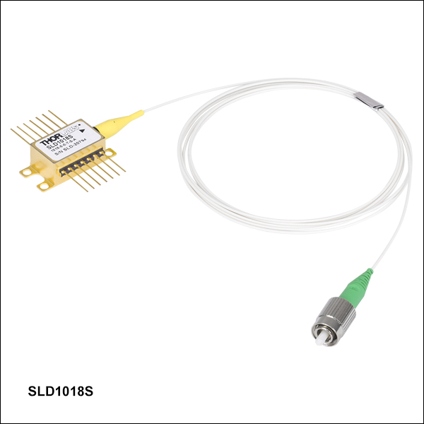
- 14-Pin Butterfly Package Pigtailed with ≥1 m of SM or PM Fiber
- 2.0 mm Narrow Key FC/APC Connector
- Integrated TEC and Thermistor
Superluminescent Diodes (SLDs) are excellent high-power, broadband light sources that are ideal for use in applications such as Optical Coherence Tomography (OCT) Imaging Systems and Fiber Optic Gyroscopes (FOG). The butterfly-packaged SLDs offered here are indium phosphide (InP) devices.
Each device is built into a 14-pin butterfly package with an integrated thermoelectric cooler (TEC) and thermistor to ensure output stability. The output is coupled into an SM or PM fiber terminated with a 2.0 mm narrow key FC/APC connector. Please note that optical feedback can diminish the output power or damage the SLD. We do not recommend using these SLDs with components that are prone to back reflections, such as FC/PC connectors. The SLD1325 1325 nm superluminescent diode incorporates an integrated isolator. If you are interested in an SLD at a different wavelength with an integrated isolator, please contact Tech Support with inquiries.
Each SLD is shipped with an individualized product data sheet, which includes information on the spectrum and operating parameters of the device. Test data for a specific SLD can be requested by contacting Tech Support.
The SLDs featured on this page have either a near-Gaussian or flat-top optical spectrum. The calculation for the center wavelength differs with these two spectral shapes. Please see the Specs tab for center wavelength calculations.
Thorlabs is able to provide low-ripple SLDs with custom wavelengths or higher power diodes. Please note that the engineering design and wafer manufacturing costs involved make the purchase of low quantities very costly. For a quote on custom SLDs, please contact Tech Support. A selection of the SLDs sold here are also available as benchtop sources. For more information, see the Selection Guide tab.
Due to the nature of producing superluminescent diodes with ultra wide bandwidths, some of the SLDs sold below have spectral shapes that are near gaussian, while others have a shape with a flattened top. This difference in spectral shape demands two different methods of defining center wavelength in order to provide an accurate description of the diode.
Near-Guassian Center Wavelength Definition
The center wavelength for devices with a near-gaussian spectral shape is defined by an average weighted by the relative amplitude and may not correspond to peak power or the FWHM center wavelength due to the variability of the spectrum shape. For a given Optical Spectrum Analyzer (OSA) trace:

where
- CW is the Specified Center Wavelength
- Xi is the Wavelength of a Trace Data Point
- Yi is the Amplitude of a Trace Data Point
Flat-Top Center Wavelength Definition
The center wavelength for devices with a flat-top spectral shape is defined by the midpoint between the two wavelengths located at 3 dB below the maximum intensity point on the spectrum. For a given OSA trace:

where
- CW is the Specified Center Wavelength
- XR_3dB is the Right Wavelength Edge of the 3 dB Bandwidth
- XL_3dB is the Left Wavelength Edge of the 3 dB Bandwidth
SLD Specifications
Note that these specifications are given as guidelines. The characterization sheet shipped with each SLD provides the minimum, maximum, and recommended operating parameters and specifications specific to that device. The ASE Power specification is the output from the fiber pigtail.
810 nm Superluminescent Diodes
| Item # | SLD810S | |||||
|---|---|---|---|---|---|---|
| Parametera | Min | Typical | Max | |||
| Operating Current | - | - | 270 mA | |||
| Center Wavelengthb | 795 nm | 810 nm | 825 nm | |||
| Spectral Shape | Near Gaussian | |||||
| ASE Powerc | 13 mW | 15 mW | - | |||
| Optical 3 dB Bandwidthc,d | 25 nm | 30 nm | - | |||
| RMS Gain Ripplec | - | 0.03 dB | 0.15 dB | |||
| Forward Voltage | - | 2.1 V | 2.5 V | |||
| Fiber | 780HP (SM) | |||||
| TEC Operation: Typ. / Max @ TCASE = 25 °C / 70 °C | ||||||
| TEC Current | - | 0.2 A | 1.4 A | |||
| TEC Voltage | - | 0.3 V | 6.0 V | |||
| Thermistor Resistance | - | 10 kΩ | - | |||
| Performance Graphs (Click Icons for Plots) | ||||||
| Output Spectrum | ||||||
| LIV Plot | ||||||
| Gain Ripplec,e | ||||||
| Absolute Maximum Ratingsa | ||||||
| Absolute Max Current | 290 mA | |||||
| Operating Case Temperature | 0 to 70 °C | |||||
| Storage Temperature | -10 to 70 °C | |||||
| Pin Code | 14 Pin, Type 1 | |||||
830 nm Superluminescent Diodes
| Item # | SLD830S-A10W | SLD830S-A20W | SLD830S-A10 | SLD830S-A20 | ||||||||
|---|---|---|---|---|---|---|---|---|---|---|---|---|
| Parametera | Min | Typical | Max | Min | Typical | Max | Min | Typical | Max | Min | Typical | Max |
| Operating Current | - | - | 240 mA | - | - | 330 mA | - | - | 150 mA | - | - | 240 mA |
| Center Wavelengthb | 815 nm | 830 nm | 845 nm | 815 nm | 830 nm | 845 nm | 820 nm | 830 nm | 840 nm | 820 nm | 830 nm | 840 nm |
| Spectral Shape | Flat Top | Flat Top | Near Gaussian | Near Gaussian | ||||||||
| ASE Powerc,d | 10 mW | - | - | 20 mW | - | - | 10 mW | 13 mW | - | 20 mW | 22 mW | - |
| Optical 3 dB Bandwidthc,e | 50 nm | 60 nm | - | 40 nm | 55 nm | - | 17 nm | 20 nm | - | 17 nm | 20 nm | - |
| Optical 20 dB Bandwidthc | - | - | - | - | - | - | - | 50 nm | - | - | 50 nm | - |
| RMS Gain Ripplec,f | - | 0.06 dB | 0.3 dB | - | 0.03 dB | 0.3 dB | - | 0.03 dB | 0.15 dB | - | 0.03 dB | 0.15 dB |
| Forward Voltage | - | 2.0 V | 2.5 V | - | 2.0 V | 2.5 V | - | 2.0 V | 2.5 V | - | 2.0 V | 2.5 V |
| Fiber Type | 780HP | 780HP | 780HP | 780HP | ||||||||
| TEC Operation: Typ. / Max @ TCASE = 25 °C / 70 °C | ||||||||||||
| TEC Current | - | 0.14 A | 1.4 A | - | 0.14 A | 1.4 A | - | 0.1 A | 1.5 A | - | 0.1 A | 1.5 A |
| TEC Voltage | - | 0.18 V | 6.0 V | - | 0.18 V | 6.0 V | - | 0.13 V | 4.0 V | - | 0.13 V | 4.0 V |
| Thermistor Resistance | - | 10 kΩ | - | - | 10 kΩ | - | - | 10 kΩ | - | - | 10 kΩ | - |
| Performance Graphs (Click Icons for Plots) | ||||||||||||
| Output Spectrum | ||||||||||||
| LIV Plot | ||||||||||||
| Gain Ripplef | ||||||||||||
| Absolute Maximum Ratingsa | ||||||||||||
| Absolute Max Current | 240 mA | 330 mA | 150 mA | 240 mA | ||||||||
| Operating Case Temperature | 0 to 70 °C | |||||||||||
| Storage Temperature | -10 to 70°C | |||||||||||
| Pin Code | 14 Pin, Type 1 | |||||||||||
850 nm Superluminescent Diodes
| Item # | SLD850S-A10W | SLD850S-A20W | ||||
|---|---|---|---|---|---|---|
| Parametera | Min | Typical | Max | Min | Typical | Max |
| Operating Current | - | - | 180 mA | - | - | 340 mA |
| Center Wavelengthb | 835 nm | 850 nm | 865 nm | 835 nm | 850 nm | 865 nm |
| Spectral Shape | Flat Top | Flat Top | ||||
| ASE Powerc,d | 10 mW | - | - | 20 mW | - | - |
| Optical 3 dB Bandwidthc,e | 40 nm | 60 nm | - | 40 nm | 55 nm | - |
| RMS Gain Ripplec,f | - | 0.03 dB | 0.3 dB | - | 0.03 dB | 0.3 dB |
| Forward Voltage | - | 2.0 V | 2.5 V | - | 2.0 V | 2.5 V |
| Fiber Type | 780HP | 780HP | ||||
| TEC Operation: Typ. / Max @ TCASE = 25 °C / 70 °C | ||||||
| TEC Current | - | 0.11 A | 1.4 A | - | 0.18 A | 1.4 A |
| TEC Voltage | - | 0.17 V | 6.0 V | - | 0.27 V | 6.0 V |
| Thermister Resistance | - | 10 kΩ | - | - | 10 kΩ | - |
| Performance Graphs (Click Icons for Plots) | ||||||
| Output Spectrum | ||||||
| LIV Plot | ||||||
| Gain Ripplef | ||||||
| Absolute Maximum Ratingsa | ||||||
| Absolute Max Current | 180 mA | 340 mA | ||||
| Operating Case Temperature | 0 to 70 °C | |||||
| Storage Temperature | -10 to 70°C | |||||
| Pin Code | 14 Pin, Type 1 | |||||
880 nm Superluminescent Diodes
| Item # | SLD880S-A7 | SLD880S-A25 | ||||
|---|---|---|---|---|---|---|
| Parametera | Min | Typical | Max | Min | Typical | Max |
| Operating Current | - | - | 225 mA | - | - | 410 mA |
| Center Wavelengthb | 860 nm | 880 nm | 900 nm | 860 nm | 880 nm | 900 nm |
| Spectral Shape | Flat Top | Flat Top | ||||
| ASE Powerc,d | 6 mW | 7 mW | - | 23 mW | 25 mW | - |
| Optical 3 dB Bandwidthc | 35 nm | 40 nm | - | 35 nm | 40 nm | - |
| Optical 20 dB Bandwidthc | - | 80 nm | - | - | 80 nm | - |
| RMS Gain Ripplec,e | - | 0.06 dB | 0.3 dB | - | 0.06 dB | 0.3 dB |
| Forward Voltagec | - | 2.0 V | 2.5 V | - | 2.0 V | 2.5 V |
| Fiber Type | 780HP | 780HP | ||||
| TEC Operation: Typ. / Max @ TCASE = 25 °C / 70 °C | ||||||
| TEC Current | - | 0.2 A | 1.4 A | - | 0.2 A | 1.4 A |
| TEC Voltage | - | 0.8 V | 6.0 V | - | 0.8 V | 6.0 V |
| Thermistor Resistance | - | 10 kΩ | - | - | 10 kΩ | - |
| Performance Graphs (Click Icons for Plots) | ||||||
| Output Spectrum | ||||||
| LIV Plot | ||||||
| Gain Ripplee | ||||||
| Absolute Maximum Ratingsa | ||||||
| Absolute Max Current | 225 mA | 410 mA | ||||
| Operating Case Temperature | 0 to 70 °C | |||||
| Storage Temperature | -10 to 70°C | |||||
| Pin Code | 14 Pin, Type 1 | |||||
930 nm Superluminescent Diodes
| Item # | SLD930x-A40W | |||||
|---|---|---|---|---|---|---|
| Parametera | Min | Typical | Max | |||
| Operating Current | - | - | 800 mA | |||
| Center Wavelengthb | 915 nm | 930 nm | 945 nm | |||
| Spectral Shape | Flat Top | |||||
| ASE Powerc,d | 36 mW | 40 mW | - | |||
| Optical 3 dB Bandwidthc,e | 40 nm | 45 nm | - | |||
| RMS Gain Ripplec,f | - | 0.06 dB | 0.3 dB | |||
| Forward Voltage | - | 2.0 V | 2.5 V | |||
| Fiber | 780HP (SM) PM780-HP (PM)g |
|||||
| TEC Operation: Typ. / Max @ TCASE = 25 °C / 70 °C | ||||||
| TEC Current | - | 0.54 A | 1.4 A | |||
| TEC Voltage | - | 0.78 V | 6.0 V | |||
| Thermister Resistance | - | 10 kΩ | - | |||
| Performance Graphs (Click Icons for Plots) | ||||||
| Output Spectrum |
|
|||||
| LIV Plot |
|
|||||
| Gain Ripplef |
|
|||||
| Absolute Maximum Ratingsa | ||||||
| Absolute Max Current | 800 mA | |||||
| Operating Case Temperature | 0 °C to 70 °C | |||||
| Storage Temperature | -10 °C to 70 °C | |||||
| Pin Code | 14 Pin, Type 1 | |||||
970 nm Superluminescent Diode
| Item # | SLD970x-A40W | ||
|---|---|---|---|
| Parametera | Min | Typical | Max |
| Operating Current | - | 1000 mA | 1010 mA |
| Center Wavelengthb | 945 nm | 970 nm | 995 nm |
| Spectral Shape | Flat Top | ||
| ASE Powerc,d | 35 mW | 40 mW | - |
| Optical 3 dB Bandwidthc,e | 40 nm | 50 nm | - |
| RMS Gain Ripplec,f | - | 0.03 dB | 0.2 dB |
| Forward Voltage | - | 1.2 V | 2.5 V |
| Fiber Type | HI1060 (SM) PM980-XP (PM)g |
||
| TEC Operation: Typ. / Max @ TCASE = 25 °C / 70 °C | |||
| TEC Current | - | 0.83 A | 1.4 A |
| TEC Voltage | - | 0.12 V | 6.0 V |
| Thermister Resistance | - | 10 kΩ | - |
| Performance Graphs (Click Icons for Plots) | |||
| Output Spectrum | |||
| LIV Plot | |||
| Gain Ripplef | |||
| Absolute Maximum Ratingsa | |||
| Absolute Max Current | 1010 mA | ||
| Operating Case Temperature | 0 °C to 70 °C | ||
| Storage Temperature | -10 °C to 70 °C | ||
| Pin Code | 14 Pin, Type 1 | ||
1050 nm Superluminescent Diodes
| Item # | SLD1050x | SLD1050S-A60 | SLD1050P-A60 | |||||||||
|---|---|---|---|---|---|---|---|---|---|---|---|---|
| Parametera | Min | Typical | Max | Min | Typical | Max | Min | Typical | Max | |||
| Operating Current | - | - | 300 mA | - | - | 1010 mA | - | - | 1010 mA | |||
| Center Wavelengthb | 1030 nm | 1050 nm | 1070 nm | 1025 nm | 1050 nm | 1075 nm | 1025 nm | 1050 nm | 1075 nm | |||
| Spectral Shape | Near Gaussian | Flat Top | Flat Top | |||||||||
| ASE Powerc,d | 6 mW | 8 mW | - | 55 mW | 60 mW | - | 55 mW | 60 mW | - | |||
| Optical 3 dB Bandwidthc,e | 40 nm | 50 nm | - | 60 nm | 70 nm | - | 60 nm | 70 nm | - | |||
| Optical 20 dB Bandwidthc | - | - | - | - | 100 nm | - | - | - | - | |||
| RMS Gain Ripplec,f | - | 0.1 dB | 0.25 dB | - | 0.03 dB | 0.2 dB | - | 0.06 dB | 0.3 dB | |||
| Forward Voltagec | - | 2.0 V | 2.5 V | - | 2.0 V | 2.5 V | - | 1.9 V | 2.5 V | |||
| Fiber Type | HI1060 (SM) PM980-XP (PM)g |
HI1060 | PM980-XPg | |||||||||
| TEC Operation: Typ. / Max @ TCASE = 25 °C / 70 °C | ||||||||||||
| TEC Current | - | 0.25 A | 1.5 A | - | 0.7 A | 2.5 A | - | 0.7 A | 2.5 A | |||
| TEC Voltage | - | 0.30 V | 4.0 V | - | 0.9 V | 3.2 V | - | 1.0 V | 3.2 V | |||
| Thermistor Resistance | - | 10 kΩ | - | - | 10 kΩ | - | - | 10 kΩ | - | |||
| Performance Graphs (Click Icons for Plots) | ||||||||||||
| Output Spectrum |
|
|||||||||||
| LIV Plot |
|
|||||||||||
| Gain Ripplef | - | |||||||||||
| Absolute Maximum Ratingsa | ||||||||||||
| Absolute Max Current | 360 mA | 1010 mA | 1010 mA | |||||||||
| Operating Case Temperature | 0 °C to 70 °C | |||||||||||
| Storage Temperature | - | -10 °C to 70 °C | ||||||||||
| Chip Temperature (TEC) | 10 °C to 30 °C | - | ||||||||||
| Pin Code | 14 Pin, Type 1 | |||||||||||
1310 nm Superluminescent Diodes
| Item # | SLD1021S | SLD1018x | |||||||
|---|---|---|---|---|---|---|---|---|---|
| Parametera | Min | Typical | Max | Min | Typical | Max | |||
| Operating Current | - | 700 mA | 900 mA | - | 600 mA | 800 mA | |||
| Center Wavelengthb | 1290 nm | - | 1330 nm | 1290 nm | - | 1330 nm | |||
| Spectral Shape | Near Gaussian | Near Gaussian | |||||||
| ASE Powerc,d | 10 mW | 12.5 mW | - | 22 mW | 30 mW | - | |||
| Optical 3 dB Bandwidthc | 80 nm | 85 nm | - | 40 nm | 45 nm | - | |||
| RMS Gain Ripplec,e | - | - | 0.35 dB | - | 0.1 dB | 0.35 dB | |||
| Forward Voltagec | - | 1.55 V | 2.0 V | - | 1.5 V | 1.8 V | |||
| Fiber Type | SMF-28e+ | SMF-28e+ (SM) Corning PM 13-U40A (PM)f |
|||||||
| TEC Operation: Typ. / Max @ TCASE = 25 °C / 65 °C | |||||||||
| TEC Current | - | 0.4 A | 1.5 A | - | 0.4 A | 1.5 A | |||
| TEC Voltage | - | 0.5 V | 4 V | - | 0.5 V | 4 V | |||
| Thermistor Resistance | - | 10 kΩ | - | - | 10 kΩ | - | |||
| Performance Plots (Click Icons for Plots) | |||||||||
| Output Spectrum | |||||||||
| LIV Plot | |||||||||
1325 nm Superluminescent Diode
| Item # | SLD1325 | ||
|---|---|---|---|
| Parametera | Min | Typical | Max |
| Operating Current | - | - | 780 mA |
| Center Wavelengthb | - | 1325 nm | - |
| Spectral Shape | Flat Top | ||
| ASE Powerc | 10 mW | - | - |
| Optical 3 dB Bandwidth | 100 nm | - | - |
| RMS Gain Ripple | - | - | - |
| Forward Voltage | - | - | 4 V |
| Fiber Type | SMF-28e | ||
| Operating Temperature Range | 0 to 40 °C | ||
| TEC Operation | |||
| TEC Current | - | - | 4 A |
| TEC Voltage | - | - | 4 V |
| Thermistor Resistanced | - | - | 10 kΩ |
| Integrated Isolator | |||
| Isolation | 30 dB | - | - |
| Performance Plots (Click Icons for Plots) | |||
| Output Spectrum | |||
| LIV Plot | |||
1550 nm Superluminescent Diodes
| Item # | SLD1550x-A1 | SLD1550x-A2 | SLD1005S | SLD1550x-A40 | ||||||||
|---|---|---|---|---|---|---|---|---|---|---|---|---|
| Parametera | Min | Typical | Max | Min | Typical | Max | Min | Typical | Max | Min | Typical | Max |
| Operating Current | - | 450 mA | 500 mA | - | 550 mA | 600 mA | - | 600 mA | 800 mA | - | 750 mA | 900 mA |
| Center Wavelengthb | 1520 nm | 1550 nm | 1580 nm | 1520 nm | 1550 nm | 1580 nm | 1530 nm | 1550 nm | 1570 nm | 1530 nm | 1550 nm | 1570 nm |
| Spectral Shape | Near Gaussian | Near Gaussian | Near Gaussian | Near Gaussian | ||||||||
| ASE Powerc,d | 0.75 mW | 1.0 mW | - | 2.0 mW | 2.5 mW | - | 20 mW | 22 mW | - | 35 mW | 40 mW | - |
| Optical 3 dB Bandwidthc | 100 nm | 110 nm | - | 85 nm | 90 nm | - | 45 nm | 50 nm | - | 30 nm | 33 nm | - |
| RMS Gain Ripplec,e | - | - | 0.1 dB | - | - | 0.25 dB | - | 0.2 dB | 0.35 dB | - | 0.2 dB | 0.35 dB |
| Forward Voltagec | - | 1.6 V | 2.0 V | - | 1.6 V | 2.0 V | - | 1.4 V | 1.8 V | - | 1.4 V | 1.8 V |
| Fiber Type | SMF-28e+ (SM) Corning PM 15-U40A (PM)f |
SMF-28e+ (SM) Corning PM 15-U40A (PM)f |
SMF-28e+ | SMF-28e+ (SM) Corning PM 15-U40A (PM)f |
||||||||
| TEC Operation: Typ. / Max @ TCASE = 25 °C / 65 °C | ||||||||||||
| TEC Current | - | 0.35 A | 1.5 A | - | 0.35 A | 1.5 A | - | 0.3 A | 1.5 A | - | 0.3 A | 1.5 A |
| TEC Voltage | - | 0.5 V | 3.5 V | - | 0.5 V | 3.5 V | - | 0.3 V | 3.5 V | - | 0.3 V | 3.5 V |
| Thermistor Resistance | - | 10 kΩ | - | - | 10 kΩ | - | - | 10 kΩ | - | - | 10 kΩ | - |
| Performance Plots (Click Icon for Plot) | ||||||||||||
| Output Spectrum | ||||||||||||
| LIV Plot | ||||||||||||
Butterfly Package, Type 1

| Pin | Description | Pin | Description |
|---|---|---|---|
| 1 | + TEC | 14 | - TEC |
| 2 | Thermistor | 13 | Case Ground |
| 3 | NC | 12 | NC |
| 4 | NC | 11 | SLD Cathode |
| 5 | Thermistor | 10 | SLD Anode |
| 6 | NC | 9 | NC |
| 7 | NC | 8 | NC |
| Posted Comments: | |
Byeong-Kwan YANG
(posted 2020-11-13 05:31:56.183) This is YANG, Byeong-Kwan of Jiny Photonics in S. Korea.
I purchased SLD830S-A20W (serial number: SLD-41707-40313.2.A04) and I am testing it now.
When measured with a low resolution spectrometer (USB4000), its spectrum comes out smoothly. We are currently manufacturing a high-resolution spectroscopy (spectral resolution 0.04 nm), and if I measure the spectrum with the spectrometer being manufactured, high-frequency components are measured.
I don't have a spectrum analyzer, so I can't get a high resolution spectrum to verify. Can I get the high resolution spectrum of the SLD830S-A20W? YLohia
(posted 2020-11-13 02:02:12.0) Hello, we measure each unit with a high resolution optical spectrum analyzer (resolution 0.02 nm). I have reached out to you directly with the data for your serial number. Ronald Dekker
(posted 2019-12-13 03:00:30.13) Can the SLD830S-A20W also be delivered with a PM fiber? YLohia
(posted 2019-12-13 09:54:13.0) Hello, we will reach out to you directly to discuss the possibility of offering this. max.koeppel
(posted 2016-09-08 06:30:40.14) Dear ladies and gentlemen,
Is the SLD1005S (22 mW SLD, CWL= 1550 nm, FWHM = 50 nm, Butterfly Pkg, SM Fiber, FC/APC) also available with a PM fiber output (FC/APC)?
Regards,
Max tfrisch
(posted 2016-09-08 11:19:30.0) Hello, I will contact you directly with a quote. hallt
(posted 2014-03-20 17:38:49.003) Hi. I'm also interested in intensity noise. Do you have any measurements for your SLDs that you could share? cdaly
(posted 2014-04-09 03:32:58.0) Response from Chris at Thorlabs: We will contact you directly information on the relative noise intensity. Laser diodes generally show a peak in the RIN curve from some resonance effects of the cavity, whereas ASE sources do not. Noise at various frequencies(frequency of intensity noise, not wavelength of the light) in ASE source would be more flat. neil.troy
(posted 2014-03-13 22:36:43.313) What fibers are used with all of these modules? myanakas
(posted 2014-03-20 12:19:08.0) Response from Mike at Thorlabs: Thank you for your feedback. Based on your feedback we have updated our web presentation to include the fiber types included with our SLDs. This information can now be found in the specification tables located in the “Specs” tab and in the Sub Groups above where the Products are sold. user
(posted 2014-01-28 10:32:58.903) Hello: what is the typical output power (normalized to peak at 1050 nm) for SLD1050S between 950 nm to 850 nm? Thanks. jlow
(posted 2014-01-30 11:51:35.0) Response from Jeremy at Thorlabs: The intensity at 950nm is estimated to be around -25dB lower than the peak. It falls sharply after that to around -60dB at 850nm. Since you did not leave your contact info, can you contact me at techsupport@thorlabs.com please? I can provide a spectral scan for a SLD1050S unit. bdada
(posted 2012-04-25 10:50:00.0) Response from Buki at Thorlabs to alexandru.serb05:
Thank you for your feedback. Gain ripple is not intensity noise. It is due to interference between two SLD facets such that, on its spectrum, you will see variation of the amplitude of the spectrum density vs. wavelength.
SLD noise only depends its bandwidth and in principle, it is frequency independent. We have done some studies on that and I have contacted you with the results. alexandru.serb05
(posted 2012-04-24 05:00:41.0) Hallo,
I just need to ask a couple of questions:
1) Could you please explain to me the concept of gain ripple? Is it variations in average output intensity:
a) between different LEDs?
b) between different frequency bins within the same LED?
c) at each frequency bin over time within the same LED?
d) Something completely different?
2) Is there a way I can see some noise plots for all these products? It would be particularly useful if I had access to such data and comparable data relating to the pigtailed laser diode range of products you offer. Noise vs frequency as measured by the same photodetector capturing the entire outgoing beam at a specificed power output is the sort of plot I have in my mind, but anything that yields meaningful comparative noise data will do. Note: both laser and non-laser diode may be assumed to be driven by a controller + TEC, but without feedback stabilisation if such data is available. Introducing feedback brings along a whole array of other parameters and will only make comparisons more difficult...
Thanks. |
Superluminescent Diode Performance:
| Item # | Center Wavelengtha | Output Powerb | Bandwidth (3 dB)b | Optical Spectrum | LIV Curvesc | Equivalent Benchtop Source |
|---|---|---|---|---|---|---|
| SLD810S | 810 nm | 15 mW | 30 nm | N/A | ||
| SLD830S-A10W | 830 nm | 10 mW (Min) | 60 nm | N/A | ||
| SLD830S-A20W | 830 nm | 20 mW (Min) | 55 nm | N/A | ||
| SLD830S-A10 | 830 nm | 13 mW | 20 nm | N/A | ||
| SLD830S-A20 | 830 nm | 22 mW | 20 nm | N/A | ||
| SLD850S-A10W | 850 nm | 10 mW (Min) | 60 nm | N/A | ||
| SLD850S-A20W | 850 nm | 20 mW (Min) | 55 nm | N/A | ||
| SLD880S-A7 | 880 nm | 7 mW | 40 nm | N/A | ||
| SLD880S-A25 | 880 nm | 25 mW | 40 nm | N/A | ||
| SLD930S-A40W | 930 nm | 40 mW | 45 nm | N/A | ||
| SLD930P-A40W | 930 nm | 40 mW | 45 nm | N/A | ||
| SLD970S-A40W | 970 nm | 40 mW | 50 nm | N/A | ||
| SLD970P-A40W | 970 nm | 40 mW | 50 nm | N/A | ||
| SLD1050S | 1050 nm | 8 mW | 50 nm | N/A | ||
| SLD1050P | 1050 nm | 8 mW | 50 nm | N/A | ||
| SLD1050S-A60 | 1050 nm | 60 mW | 70 nm | N/A | ||
| SLD1050P-A60 | 1050 nm | 60 mW | 70 nm | N/A | ||
| SLD1021S | 1310 nm | 12.5 mW | 85 nm | S5FC1021S | ||
| SLD1018S | 1310 nm | 30 mW | 45 nm | S5FC1018S S5FC1018P |
||
| SLD1018P | 1310 nm | 30 mW | 45 nm | S5FC1018S S5FC1018P |
||
| SLD1325 | 1325 nm | 10 mW (Min) | 100 nm (Min) | N/A | ||
| SLD1550S-A1 | 1550 nm | 1.0 mW | 110 nm | N/A | ||
| SLD1550P-A1 | 1550 nm | 1.0 mW | 110 nm | N/A | ||
| SLD1550S-A2 | 1550 nm | 2.5 mW | 90 nm | S5FC1550S-A2 S5FC1550P-A2 |
||
| SLD1550P-A2 | 1550 nm | 2.5 mW | 90 nm | S5FC1550S-A2 S5FC1550P-A2 |
||
| SLD1005S | 1550 nm | 22 mW | 50 nm | S5FC1005S | ||
| SLD1550S-A40 | 1550 nm | 40 mW | 33 nm | N/A | ||
| SLD1550P-A40 | 1550 nm | 40 mW | 33 nm | N/A |

 Zoom
ZoomIn order to support OCT imaging applications, these SLDs are designed with a low gain ripple no higher than 0.15 dB (RMS) and a typical ripple value of 0.03 dB (RMS). More information on Thorlabs' SLDs for OCT systems can be found here. Note that the bandwidth will decrease as the current is decreased; bandwidth specifications below are specified at the operating current.
| Item #a | SLD810S | ||
|---|---|---|---|
| Parameter | Min | Typ. | Max |
| Operating Current | - | - | 270 mA |
| Center Wavelengthb | 795 nm | 810 nm | 825 nm |
| Spectral Shape | Near Gaussian | ||
| ASE Powerc | 13 mW | 15 mW | - |
| Optical 3 dB Bandwidthc,d | 25 nm | 30 nm | - |
| RMS Gain Ripplec,e | - | 0.03 dB | 0.15 dB |
| Fiber Type | 780HP | ||
| Performance Graphs (Click Icons for Plots) | |||
| Output Spectrum | |||
| LIV Plot | |||
| Gain Ripplee | |||

 Zoom
ZoomIn order to support OCT imaging applications, these SLDs are designed with a low gain ripple no higher than 0.3 dB (RMS) and a typical ripple value of 0.03 dB (RMS). More information on Thorlabs' SLDs for OCT systems can be found here. Note that the bandwidth will decrease as the current is decreased; bandwidth specifications below are specified at the operating current.
| Item #a | SLD830S-A10W | SLD830S-A20W | SLD830S-A10 | SLD830S-A20 | ||||||||
|---|---|---|---|---|---|---|---|---|---|---|---|---|
| Parameter | Min | Typ. | Max | Min | Typ. | Max | Min | Typ. | Max | Min | Typ. | Max |
| Operating Current (mA) | - | - | 240 | - | - | 330 | - | - | 150 | - | - | 240 |
| Center Wavelength (nm)b | 815 | 830 | 845 | 815 | 830 | 845 | 820 | 830 | 840 | 820 | 830 | 840 |
| Spectral Shape | Flat Top | Flat Top | Near Gaussian | Near Gaussian | ||||||||
| ASE Power (mW)c,d | 10 | - | - | 20 | - | - | 10 | 13 | - | 20 | 22 | - |
| Optical 3 dB Bandwidth (nm)c,e | 50 | 60 | - | 40 | 55 | - | 17 | 20 | - | 17 | 20 | - |
| Optical 20 dB Bandwidth (nm)c | - | - | - | - | - | - | - | 50 | - | - | 50 | - |
| RMS Gain Ripple (dB)c,f | - | 0.06 | 0.3 | - | 0.03 | 0.3 | - | 0.03 | 0.15 | - | 0.03 | 0.15 |
| Fiber Type | 780HP | 780HP | 780HP | 780HP | ||||||||
| Performance Graphs (Click Icons for Plots) | ||||||||||||
| Output Spectrum | ||||||||||||
| LIV Plot | ||||||||||||
| Gain Ripplef | ||||||||||||

 Zoom
ZoomIn order to support OCT imaging applications, these SLDs are designed with a low gain ripple no higher than 0.3 dB (RMS) and a typical ripple value of 0.03 dB (RMS). More information on Thorlabs' SLDs for OCT systems can be found here. Note that the bandwidth will decrease as the current is decreased; bandwidth specifications below are specified at the operating current.
| Item #a | SLD850S-A10W | SLD850S-A20W | ||||
|---|---|---|---|---|---|---|
| Parameter | Min | Typ. | Max | Min | Typ. | Max |
| Operating Current (mA) | - | - | 180 | - | - | 340 |
| Center Wavelength (nm)b | 835 | 850 | 865 | 835 | 850 | 865 |
| Spectral Shape | Flat Top | Flat Top | ||||
| ASE Power (mW)c,d | 10 | - | - | 20 | - | - |
| Optical 3 dB Bandwidth (nm)c,e | 40 | 60 | - | 40 | 55 | - |
| RMS Gain Ripple (dB)c,f | - | 0.03 | 0.3 | - | 0.03 | 0.3 |
| Fiber Type | 780HP | 780HP | ||||
| Performance Graphs (Click Icons for Plots) | ||||||
| Output Spectrum | ||||||
| LIV Plot | ||||||
| Gain Ripplef | ||||||

 Zoom
ZoomThese SLDs are designed to be used in OCT imaging applications. They have a low gain ripple no larger than 0.3 dB (RMS) and a typical ripple value 0.03 dB (RMS). More information on Thorlabs' SLDs for OCT systems can be found here. Note that the bandwidth will decrease as the current is decreased; bandwidth specifications below are specified at the operating current.
| Item #a | SLD880S-A7 | SLD880S-A25 | ||||
|---|---|---|---|---|---|---|
| Parametera | Min | Typ. | Max | Min | Typ. | Max |
| Operating Current (mA) | - | - | 225 | - | - | 410 |
| Center Wavelength (nm)b | 860 | 880 | 900 | 860 | 880 | 900 |
| Spectral Shape | Flat Top | Flat Top | ||||
| ASE Power (mW)c,d | 6 | 7 | - | 23 | 25 | - |
| Optical 3 dB Bandwidth (nm)c | 35 | 40 | - | 35 | 40 | - |
| Optical 20 dB Bandwidth (nm)c | - | 80 | - | - | 80 | - |
| RMS Gain Ripple (dB)c,e | - | 0.06 | 0.3 | - | 0.06 | 0.3 |
| Fiber Type | 780HP | 780HP | ||||
| Performance Graphs (Click Icons for Plots) | ||||||
| Output Spectrum | ||||||
| LIV Plot | ||||||
| Gain Ripplee | ||||||

 Zoom
ZoomThese SLDs are designed to be used in OCT imaging applications. They have a low gain ripple no larger than 0.3 dB (RMS) and a typical ripple value 0.06 dB (RMS). More information on Thorlabs' SLDs for OCT systems can be found here. Note that the bandwidth will decrease as the current is decreased; bandwidth specifications below are specified at the operating current.
| Item #a | SLD930x-A40W | ||||
|---|---|---|---|---|---|
| Parameter | Min | Typ. | Max | ||
| Operating Current (mA) | - | - | 800 | ||
| Center Wavelength (nm)b | 915 | 930 | 945 | ||
| Spectral Shape | Flat Top | ||||
| ASE Power (mW)c,d | 36 | 40 | - | ||
| Optical 3 dB Bandwidth (nm)c | 40 | 45 | - | ||
| RMS Gain Ripple (dB)c,e | - | 0.06 | 0.3 | ||
| Fiber Type | 780HP (SM) PM780-HP (PM)f |
||||
| Performance Graphs (Click Icons for Plots) | |||||
| Output Spectrum |
|
||||
| LIV Plot |
|
||||
| Gain Ripplee |
|
||||

 Zoom
ZoomIn order to support OCT imaging applications, these SLDs are designed with a low gain ripple no higher than 0.2 dB (RMS) and a typical ripple value of 0.03 dB (RMS). More information on Thorlabs' SLDs for OCT systems can be found here. Note that the bandwidth will decrease as the current is decreased; bandwidth specifications below are specified at the operating current.
| Item #a | SLD970x-A40W | ||
|---|---|---|---|
| Parameter | Min | Typical | Max |
| Operating Current (mA) | - | 1000 | 1010 |
| Center Wavelength (nm)b | 945 | 970 | 995 |
| Spectral Shape | Flat Top | ||
| ASE Power (mW)c,d | 35 | 40 | - |
| Optical 3 dB Bandwidth (nm)c,e | 40 | 50 | - |
| RMS Gain Ripple (dB)c,f | - | 0.03 | 0.2 |
| Fiber Type | HI1060 (SM) PM980-XP (PM)g |
||
| Performance Graphs (Click Icons for Plots) | |||
| Output Spectrum | |||
| LIV Plot | |||
| Gain Ripplef | |||

 Zoom
ZoomThe SLD1050S-A60 is designed to be used in OCT imaging applications. More information on Thorlabs' SLDs for OCT systems can be found here. Note that the bandwidth will decrease as the current is decreased; bandwidth specifications below are specified at the operating current.
| Item #a | SLD1050S | SLD1050P | SLD1050S-A60 | SLD1050P-A60 | ||||||||
|---|---|---|---|---|---|---|---|---|---|---|---|---|
| Parameter | Min | Typ. | Max | Min | Typ. | Max | Min | Typ. | Max | Min | Typ. | Max |
| Operating Current (mA) | - | - | 300 | - | - | 300 | - | - | 1010 | - | - | 1010 |
| Center Wavelength (nm)b | 1030 | 1050 | 1070 | 1030 | 1050 | 1070 | 1025 | 1050 | 1075 | 1025 | 1050 | 1075 |
| Spectral Shape | Near Gaussian | Near Gaussian | Flat Top | Flat Top | ||||||||
| ASE Power (mW)c,d | 6 | 8 | - | 6 | 8 | - | 55 | 60 | - | 55 | 60 | - |
| Optical 3 dB Bandwidth (nm)c,e | 40 | 50 | - | 40 | 50 | - | 60 | 70 | - | 60 | 70 | - |
| Optical 20 dB Bandwidth (nm)c | - | - | - | - | - | - | - | 100 | - | - | - | - |
| RMS Gain Ripple (dB)c,f | - | 0.1 | 0.25 | - | 0.1 | 0.25 | - | 0.03 | 0.2 | - | 0.06 | 0.3 |
| Fiber Type | HI1060 | PM980-XPg | HI1060 | PM980-XPg | ||||||||
| Performance Graphs (Click Icons for Plots) | ||||||||||||
| Output Spectrum | ||||||||||||
| LIV Plot | ||||||||||||
| Gain Ripplef | - | - | ||||||||||

 Zoom
ZoomNote that the bandwidth will decrease as the current is decreased; bandwidth specifications below are specified at the operating current.
| Item #a | SLD1021S | SLD1018x | ||||
|---|---|---|---|---|---|---|
| Parameter | Min | Typ. | Max | Min | Typ. | Max |
| Operating Current (mA) | - | 700 | 900 | - | 600 | 800 |
| Center Wavelength (nm)b | 1290 | - | 1330 | 1290 | - | 1330 |
| Spectral Shape | Near Gaussian | Near Gaussian | ||||
| ASE Power (mW)c,d | 10 | 12.5 | - | 22 | 30 | - |
| Optical 3 dB Bandwidth (nm)c | 80 | 85 | - | 40 | 45 | - |
| RMS Gain Ripple (dB)c,e | - | - | 0.35 | - | 0.1 | 0.35 |
| Fiber Type | SMF-28e+ | SMF-28e+ (SM) Corning PM 13-U40A (PM)f |
||||
| Benchtop Version | S5FC1021S | S5FC1018S (SM) S5FC1018P (PM) |
||||
| Performance Plots (Click Icons for Plots) | ||||||
| Output Spectrum | ||||||
| LIV Plot | ||||||

 Zoom
ZoomThe SLD1325 is designed to have a broad bandwidth of >100 nm for improved resolution when used in Spectral Domain Optical Coherence Tomography (SD-OCT) systems. This SLD is packaged with an integrated TEC and thermistor for temperature control, as well as an optical isolator for enhanced optical stability. More information on Thorlabs' SLDs for OCT systems can be found here. Note that the bandwidth will decrease as the current is decreased; bandwidth specifications below are specified at the operating current.
| Item #a | SLD1325 | ||
|---|---|---|---|
| Parameter | Min | Typ. | Max |
| Operating Current (mA) | - | - | 780 |
| Center Wavelength (nm)b | - | 1325 | - |
| Spectral Shape | Flat Top | ||
| ASE Power (mW)c | 10 | - | - |
| Optical 3 dB Bandwidth (nm) | 100 | - | - |
| Fiber Type | SMF-28e | ||
| Integrated Optical Isolator | |||
| Isolation (dB) | 30 | - | - |
| Performance Plots (Click Icons for Plots) | |||
| Output Spectrum | |||
| LIV Plot | |||

 Zoom
ZoomNote that the bandwidth will decrease as the current is decreased; bandwidth specifications below are specified at the operating current.
| Item #a | SLD1550x-A1 | SLD1550x-A2 | SLD1005S | SLD1550x-A40 | ||||||||
|---|---|---|---|---|---|---|---|---|---|---|---|---|
| Parameter | Min | Typ. | Max | Min | Typ. | Max | Min | Typ. | Max | Min | Typ. | Max |
| Operating Current (mA) | - | 450 | 500 | - | 550 | 600 | - | 600 | 800 | - | 750 | 900 |
| Center Wavelength (nm)b | 1520 | 1550 | 1580 | 1520 | 1550 | 1580 | 1530 | 1550 | 1570 | 1530 | 1550 | 1570 |
| Spectral Shape | Near Gaussian | Near Gaussian | Near Gaussian | Near Gaussian | ||||||||
| ASE Power (mW)c,d | 0.75 | 1.0 | - | 2.0 | 2.5 | - | 20 | 22 | - | 35 | 40 | - |
| Optical 3 dB Bandwidth (nm)c | 100 | 110 | - | 85 | 90 | - | 45 | 50 | - | 30 | 33 | - |
| RMS Gain Ripple (dB)c,e | - | - | 0.1 | - | - | 0.25 | - | 0.2 | 0.35 | - | 0.2 | 0.35 |
| Fiber Type | SMF-28e+ (SM) Corning PM 15-U40A (PM)f |
SMF-28e+ | SMF-28e+ (SM) Corning PM 15-U40A (PM)f |
|||||||||
| Benchtop Version | N/A | S5FC1550S-A2 (SM) S5FC1550P-A2 (PM) |
S5FC1005S | N/A | ||||||||
| Performance Plots (Click Icon for Plot) | ||||||||||||
| Output Spectrum | ||||||||||||
| LIV Plot | ||||||||||||