 Products Home / Motion Control Electronics / Auto-Alignment / Kinesis® K-Cube™ NanoTrak® Fiber Alignment Controllers
Kinesis® K-Cube™ NanoTrak® Fiber Alignment Controllers

- Maintain Long-Term Fiber Alignment
- Two Outputs for Driving Piezo Actuators
- Visible (320 to 1000 nm) or IR (900 to 1700 nm) Detector
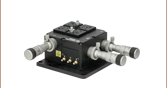
KNA-VIS
320 nm - 1000 nm
(Power Supply Sold Separately)
Table Mounting Plate (Included with K-Cube)
KNA-IR
900 nm - 1700 nm (Shown on Included Mounting Plate)


Please Wait

Click to Enlarge
Back View of the K-Cube NanoTrak® Controller (See the Pin Diagrams Tab for More Information)

Click to Enlarge
Top View of the K-Cube NanoTrak® Controller
Applications
- Fiber-to-Fiber Active Alignment
- Fiber-to-Free-Space Active Alignment
- Fiber Characterization
| NanoTrak® Fiber Alignment Controllers | |||||
|---|---|---|---|---|---|
| K-Cube 2-Channel Controllers | |||||
| Benchtop 2-Channel Controller | |||||
| Modular 2-Channel Rack System Module | |||||
| K-Cube™ Motion Control Modules | |||||
| Brushed DC Servo Motor Controller | |||||
| Brushless DC Servo Motor Controller | |||||
| Four-Channel Piezo Inertia Actuator Controller | |||||
| PSD Auto Aligner | |||||
| Single-Channel Piezo Controller | |||||
| Single-Channel Strain Gauge Reader | |||||
| Solenoid Controller | |||||
| Stepper Motor Controller | |||||
Features
- Compact Footprint: 121 mm x 60 mm x 47 mm
- Two Piezo Actuator Output Channels Provide Closed-Loop Feedback
- Two Detector Options:
- Si for 320 to 1000 nm
- InGaAs for 900 nm to 1700 nm
- Control Using Top Panel or PC Software via USB Plug-and-Play Connectivity
- Tracking Mode Achieves and Maintains Optimum Throughput
- Latched Mode Maintains Stable Positioning
- Full Kinesis® Software Control Suite Included (See Kinesis Software Tab for Details)
- Magnetic, Clip-On Optical Table Mounting Adapter Included
- Single- and Multi-Channel PSU Options Available Separately
K-Cube™ NanoTrak® Fiber Alignment Controllers are a part of Thorlabs' new and growing Kinesis® line of high-end, compact motion controllers. The fiber alignment controllers are designed to maximize the power throughput of a fiber-to-fiber or fiber-to-free-space system. By driving a piezo-actuated stage to move the fiber tip in a circular scan pattern, the controller performs a power gradient search to determine the direction of peak power and positions the fiber for maximum throughput. Two high-voltage output channels provide the drive signal for the associated piezo actuators, eliminating the need for external piezo drivers. In combination with a multi-axis, piezo-driven stage, such as our 3-Axis NanoMax and 6-Axis NanoMax stages, a K-Cube fiber alignment controller creates a complete, compact auto-alignment system (see the Application tab for more details).
The small footprint of this unit (121 mm x 60 mm x 47 mm) and quickly detachable mounting plate allow the K-Cube to be securely mounted to an optical table in close proximity to the system it controls. Each controller comes with a preinstalled detector. The KNA-VIS has a Si detector optimized for the visible spectrum (320 nm to 1000 nm), while the KNA-IR has an InGaAs detector for the infrared (900 nm to 1700 nm). The front of each unit features a power switch that, when turned off, saves all user-adjustable settings. Top panel controls enable convenient standalone operation, and the easy-to-read digital display allows the user to monitor the alignment.
USB connectivity provides easy 'Plug-and-Play' PC-controlled operation with the Kinesis software package, which features new .NET controls that can be used by third-party developers working in the latest C, C#, LabVIEW™ or any .NET compatible languages to create custom applications. A USB 3.0 type A to type Micro B cable is included with each K-Cube NanoTrak controller. For more details, please see the Kinesis Software and Kinesis Tutorials tabs.
Optical Table Mounting Plate
Each unit comes with a mounting plate that clips onto the base of the module. The plate contains two magnets for temporary placement on an optical table and two counterbores for 1/4"-20 (M6) cap screws for a more permanent placement on the tabletop. Please see the Specs for a mechanical drawing of the table mounting plate and the Mounting Options tab for how to mount the plate.
Power Supply Options
The preferred power supply (multi-channel or hub-based) depends on the end user's application and whether you already own compatible power supplies. To that end and in keeping with Thorlabs' green initiative, we do not ship these units bundled with a power supply.
The TPS002 Power Supply Unit should only be used to power a single KNA-VIS or KNA-IR unit to avoid exceeding current limitations. The KCH301 or KCH601 USB Controller Hubs, available below, are ideal for applications involving multiple K-Cubes and/or T-Cubes. The KCH301 features three controller mounting bays while the KCH601 features six controller mounting bays. These K-Cube NanoTrak controllers occupy two mounting bays, so only the KCH601 hub can be used to power multiple K-Cube NanoTrak controllers. All compatible power supply options can be found below.
| Item # | KNA-VIS | KNA-IR |
|---|---|---|
| Optical Power Measurement | ||
| Photodiode Type | Si | InGaAs |
| Optical Input Connector | FC/PC | |
| Detector Photocurrent | 5 nA to 2.5 mA | |
| Saturation Power | 4 mW | 1.5 mW |
| Wavelength | 320 to 1000 nm | 900 to 1700 nm |
| Optical Power Monitor (SMA) | Multiple Ranges | |
| Signal Phase Compensation | -180° to 180° | |
| Power Gradient Search | ||
| Circle Scanning Frequency | 4.4 to 87.5 Hz | |
| Circle Position Range | <1% to >99% Max Piezo Extension | |
| Circle Diameter Adjustment Modes | Automatic or Manual | |
| Piezoelectric Input/Output | ||
| HV OUT Connectors (SMC Male) |
Voltage Output: 0 to 150 VDC/Channel Current Output: 7.5 mA/Channel |
|
| MONITOR Outputs (SMA) | 0 to 10 VDC | |
| EXT IN Analog Inputs (SMA) | 0 to 10 VDC | |
| Other Input/Output | ||
| I/O 1 Auxiliary Input/Output | Trigger I/O: 0 to 5 V, External Input: 0 to 2 V | |
| I/O 2 Auxiliary Input/Output | Trigger I/O: 0 to 5 V, External Output: 0 to 2 V | |
| Input Power Requirements | ||
| Voltage | +5 V (160 mA), +15 V (380 mA), -15 V (60 mA), | |
| Power | <3 W | |
| General | ||
| USB Connection Speed | USB 1.1 | |
| Housing Dimensionsa | 121 mm x 60 mm x 47 mm (4.8" x 2.4" x 1.8") | |
| Weight | 0.45 kg (0.99 lb) | |

Click to Enlarge
Mechanical Drawing of K-Cube NanoTrak® Fiber Alignment Controller
Computer Connection*

*The USB 3.0 port is compatible with a USB 2.0 Micro B connector if the Micro B connector is plugged into the shaded region in the photo above. A USB 3.0 type A to type Micro B cable is included with the K-Cube NanoTrak® Controller.
I/O 1SMA Female |
I/O 2SMA Female |
 |
|
| +5 V TTL | +5 V TTL |
|
These ports are dual purpose. They can be used as a trigger input and output (0 to 5 V). I/O 1 may be also used as an external input (0 to 2 V), amplifying the input signal and presenting it as a drive signal at the HV OUT connectors on the rear panel. I/O 2 may be also used as an external output (0 to 2 V), providing an analogue monitor OUT for the PIN photodiode. I/O 2 may be connected to I/O 1 for use in a dual NanoTrak® setup. |
|
Power Connector
Mini-DIN Female

| Pin | Description | Pin | Description |
|---|---|---|---|
| 1 | +5 V | 6 | Common Ground |
| 2 | +5 V | 7 | Common Ground |
| 3 | -15 V | 8 | Common Ground |
| 4 | +15 V | Shield | Common Ground |
| 5 | +5 V |
MONITOR 1SMA Female |
MONITOR 2SMA Female |
HV OUT 1SMC Male |
HV OUT 2SMC Male |
EXT IN 1SMA Female |
EXT IN 2SMA Female |
|
|
 |
|
|
|
| These low-voltage (0 to +10 V) outputs can be used to monitor the signal at the associated HV OUT high-voltage outputs. They are usually connected directly to an oscilloscope to observe the waveforms or voltage levels present at the high-voltage outputs. | These outputs (0 to 150 V, 0 to 7.5 mA) provide the drive signal to the associated piezo actuators. The maximum voltage (75 V or 150 V) can be set via the front panel or software | Used to receive a piezo feedback signal from a source such as the KSG101 Strain Gauge Reader. The input voltage range is 0 to +10 V and the input impedance is 10 kΩ. | |||
K-Cube Mounting Options
Two options are available to securely mount our K-Cube controllers onto an optical table. An optical table mounting plate, provided with every K-Cube, allows for a single controller to be attached to an optical table. Alternatively, three- and six-port USB controller hubs are offered (sold separately) that can mount and power our K-Cube controllers. These options are described in further detail below.
Optical Table Mounting Plate
Each K-Cube unit comes with a mounting plate that clips onto the base of the controller, as shown in the animation below. The plate contains two magnets for temporary placement on an optical table and two counterbores for 1/4"-20 (M6) cap screws for a more permanent placement on the tabletop. Please see the Specs tab for a mechanical drawing of the table mounting plate.
Kinesis USB Controller Hubs
Multiple units can be mounted and connected to a single PC by using the KCH301 or KCH601 USB Controller Hubs. They each consist of two parts: the hub, which can support up to three (KCH301) or six (KCH601) K-Cubes or T-Cubes, and a power supply that plugs into a standard wall outlet. K-Cubes simply clip into place using the provided on-unit clips, while current- and previous-generation T-Cubes require the KAP101 Adapter Plate, shown in the animation below. The hub vastly reduces the number of USB and power cables required when operating multiple controllers.
K-Cube Table Mounting Plate
Unlike T-Cubes, every K-Cube includes a mounting plate that clips onto the base of the controller. The plate contains two magnets for temporary placement on an optical table and two counterbores for 1/4"-20 (M6) cap screws for more permanent placement on the tabletop.
Kinesis USB Controller Hubs
3- and 6-Port USB Controller Hubs allow multiple controllers to be connected to one PC for multi-axis applications. K-Cubes can be directly attached to the hubs while T-Cubes require a KAP101 Adapter Plate.
Thorlabs' Kinesis® software can be used to control devices in the Kinesis or APT family, which covers a wide range of devices ranging from small, low-powered, single-channel drivers (such as the K-Cubes and T-Cubes) to high-power, multi-channel, modular 19" rack nanopositioning systems (the APT Rack System).
The Kinesis Software features new .NET controls which can be used by 3rd party developers working in the latest C#, Visual Basic, LabVIEW™ or any .NET compatible languages to create custom applications. Low level DLL libraries are included for applications not expected to use the .NET framework. A Central Sequence Manager supports integration and synchronization of all Thorlabs motion control hardware.
The software packages allow two methods of usage: graphical user interface (GUI) utilities for direct interaction with and control of the controllers 'out of the box', and a set of programming interfaces that allow custom-integrated positioning and alignment solutions to be easily programmed in the development language of choice.
Software
Kinesis Version 1.14.25
The Kinesis Software Package, which includes a GUI for control of Thorlabs' Kinesis and APT™ system controllers.
Also Available:
- Communications Protocol

Click to Enlarge
Kinesis GUI Screen for K-Cube NanoTrak® Controllers
Thorlabs' Kinesis® software features new .NET controls which can be used by third-party developers working in the latest C#, Visual Basic, LabVIEW™, or any .NET compatible languages to create custom applications.
C#
This programming language is designed to allow multiple programming paradigms, or languages, to be used, thus allowing for complex problems to be solved in an easy or efficient manner. It encompasses typing, imperative, declarative, functional, generic, object-oriented, and component-oriented programming. By providing functionality with this common software platform, Thorlabs has ensured that users can easily mix and match any of the Kinesis controllers in a single application, while only having to learn a single set of software tools. In this way, it is perfectly feasible to combine any of the controllers from the low-powered, single-axis to the high-powered, multi-axis systems and control all from a single, PC-based unified software interface.
The Kinesis System Software allows two methods of usage: graphical user interface (GUI) utilities for direct interaction and control of the controllers 'out of the box', and a set of programming interfaces that allow custom-integrated positioning and alignment solutions to be easily programmed in the development language of choice.
For a collection of example projects that can be compiled and run to demonstrate the different ways in which developers can build on the Kinesis motion control libraries, click on the links below. Please note that a separate integrated development environment (IDE) (e.g., Microsoft Visual Studio) will be required to execute the Quick Start examples. The C# example projects can be executed using the included .NET controls in the Kinesis software package (see the Kinesis Software tab for details).
 |
Click Here for the Kinesis with C# Quick Start Guide Click Here for C# Example Projects Click Here for Quick Start Device Control Examples |
|
LabVIEW
LabVIEW can be used to communicate with any Kinesis- or APT-based controller via .NET controls. In LabVIEW, you build a user interface, known as a front panel, with a set of tools and objects and then add code using graphical representations of functions to control the front panel objects. The LabVIEW tutorial, provided below, provides some information on using the .NET controls to create control GUIs for Kinesis- and APT-driven devices within LabVIEW. It includes an overview with basic information about using controllers in LabVIEW and explains the setup procedure that needs to be completed before using a LabVIEW GUI to operate a device.
 |
Click Here to View the LabVIEW Guide Click Here to View the Kinesis with LabVIEW Overview Page |
|
| K-Cube vs. T-Cube Feature Comparison | ||
|---|---|---|
| Feature | KNA-VIS & KNA-IR K-Cubes | TNA001/VIS & TNA001/IR T-Cubes |
| Kinesis Software Compatibility | ||
| APT Software Compatibility | N/A | |
| Kinesis USB Controller Hubs Compatibility |
Requires KAP101 Adapter | |
| TCH002 T-Cube USB Controller Hubs Compatibility |
N/A | |
| Power Switch | N/A | |
| Piezo Control | High Voltage Output to Drive Piezo Actuators |
Closed-Loop Feedback to Piezo Drivers |
| Bidirectional SMA I/O Porta | 2 | N/A |
| SMA Monitor Outputa | 2 | |
| SMA External Analog Inputa | 2 | |
| Computer Connectiona | USB 3.0 Micro B (USB 2.0 Compliant) |
USB 2.0 Mini-B (USB 2.0 Compliant) |
| Included Mounting Plate | ||
| Size (L x W x H) |
121.0 mm x 60.0 mm x 47.0 mm (4.76" x 2.36" x 1.85") |
60.0 mm x 60.0 mm x 47.0 mm (4.76" x 2.36" x 1.85") |
| On-Unit Controls | Color LCD Display with Wheel | LED Display with Buttons |
| Track/Latch Modes | ||
| Piezo Drive Voltage | N/A | |
| I/O Signal | N/A | |
| Screen Brightness | N/A | |
Introducing Thorlabs' Kinesis® Motion Controllers
A major upgrade to the former-generation T-Cubes™, the growing K-Cube™ line of high-end controllers provides increased versatility not only through the new Kinesis software, but through an overhaul and updating of their physical design and firmware.
Every K-Cube controller includes a digital display. In addition to basic input and output readouts, this display hosts a number of menu options that include go-to-position commands, homing, velocity control, and jogging. The on-unit velocity wheel and menu button are used to scroll through the available options. Each unit contains a front-located power switch that, when turned off, saves all user-adjustable settings as well as two bidirectional SMA trigger ports that accept or output a 5 V TTL logic signal.
Please see the table to the right for a full comparison of the features offered by our new KNA-VIS and KNA-IR K-Cubes and previous-generation T-Cube fiber alignment controllers.

Click to Enlarge
KNA-VIS K-Cube Kinesis NanoTrak® Controller
Kinesis USB Controller Hubs
Complementing our K-Cubes are our Kinesis USB 2.0 controller hubs. With two versions available for three or six K- or T-Cubes, these USB hubs are designed specifically for communication between multiple controllers and the host control PC. These hubs are backward compatible with our T-Cubes.
K-Cubes simply clip into place using the provided on-unit clips, while current- and previous-generation T-Cubes require the KAP101 Adapter Plate, shown in the animation to the below right. The hub vastly reduces the number of USB and power cables required when operating multiple controllers.
K-Cube Table Mounting Plate
Unlike T-Cubes, every K-Cube includes a mounting plate that clips onto the base of the controller. The plate contains two magnets for temporary placement on an optical table and two counterbores for 1/4"-20 (M6) cap screws for more permanent placement on the tabletop.
Kinesis USB Controller Hubs
3- and 6-Port USB Controller Hubs allow multiple controllers to be connected to one PC for multi-axis applications. K-Cubes can be directly attached to the hubs while T-Cubes require a KAP101 Adapter Plate.
K-Cube™ NanoTrak® Fiber Alignment Application
A K-Cube™ NanoTrak® Fiber Alignment Controller can be used in conjunction with a NanoMax Flexure Stage to create a continuous active fiber alignment system. Light from a K-Cube laser source is transmitted through the input fiber to the fiber end attached to the moving world of the stage. An output fiber is fixed to the stationary portion of the stage, and the light transmitted through the second fiber is fed into the power sensor on the NanoTrak controller.
The NanoTrak controller looks for the gradient in the power signal to determine the direction of peak power. This is achieved by scanning the stage in a circular path. As the input fiber is driven in a circle, the optical power coupling between the two fibers will fluctuate. The NanoTrak samples the power at multiple points around the test circle and then directs the piezos to move the stage in the direction of the highest signal. This process is continued until the highest power lies in the center of the circle and the power at every point on the circle is equal.
Continuous active alignment (Tracking Mode) can be used to maintain alignment in a setup, or the gradient search can be halted (Latched Mode) for next step assembly or R&D operations. The setup below can be used for fiber characterization and testing. If the output fiber is replaced with one of our Fiber Optic Couplers, the same setup may be used to maintain high power throughput to an entire fiber-based setup.

Click to Enlarge
Fiber-to-Fiber Auto-Alignment Setup Using a K-Cube NanoTrak® to Control a NanoMax Stage
| Suggested Components | ||
|---|---|---|
| Laser Source | KLS635 K-Cube Laser Source | KLS1550 K-Cube Laser Source |
| Fiber Patch Cables | Two Fiber Patch Cables Are Required | |
| Fiber Alignment Controller | KNA-VIS | KNA-IR |
| NanoMax Flexure Stage (Choose One) |
MAX312D (MAX312D/M) 3-Axis Stage, Open-Loop Piezos MAX311D (MAX311D/M) 3-Axis Stage, Closed-Loop Piezos MAX381 (MAX381/M) 3-Axis Stage, Closed-Loop Piezosa |
|
| Extension Platform | AMA009 (AMA009/M) Fixed Platform Bracket | |
| Fiber Holder (Two Required) |
HFB001 SMA Fiber Holder for Multi-Axis Stages HFB004 FC/PC Fiber Holder for Multi-Axis Stages HFB005 FC/APC Fiber Holder for Multi-Axis Stages |
|
| Posted Comments: | |
Andrew Barrette
(posted 2020-09-01 11:22:30.513) This is a great system for aligning our pulsed laser into an optical fiber but, on it's own, the NanoTrak alignment algorithm doesn't work with our pulsed laser. We solved the problem by using a lock-in detector to convert the pulsed signal from the alignment photodiode to a CW signal.
It would be nice if you could build this functionality into the NanoTrak controller. I'm imagining a "Sync" BNC port on the controller that takes a sync signal from the laser. cwright
(posted 2020-09-03 08:19:44.0) Response from Charles at Thorlabs: Hello Andrew and thank you for your feedback! We understand there is increasing interest in using our alignment devices with pulsed sources and your suggestion is something I will present on our internal engineering forums for future design considerations. klee
(posted 2009-09-14 12:40:46.0) A response from Ken at Thorlabs to emsicustomer: "apt" stands for "Advanced Positioning Technology". emsicustomer
(posted 2009-09-14 11:45:22.0) What does "apt" stand for? |

 Zoom
ZoomThe K-Cube™ NanoTrak® Fiber Alignment Controllers optimize the coupling power when aligning fiber and free-space devices. Two options are available: the KNA-VIS controller is shipped with a preinstalled Si detector for 320 nm to 1000 nm, while the KNA-IR controller is shipped with a preinstalled InGaAs detector for 900 nm to 1700 nm.
Power supply options for the K-Cubes are sold separately below.

 Zoom
Zoom- Individual ±15 V/5 V Power Supply
- TPS002: For up to Two K-Cubes™ or T-Cubes™ with Mini-DIN Input*
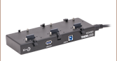
- USB Controller Hubs Provide Power and Communications
- KCH301: For up to Three K-Cubes or T-Cubes
- KCH601: For up to Six K-Cubes or T-Cubes
The TPS002 supplies power for up to two K-Cubes* or T-Cubes. The cubes still require individual computer connection via USB cable.
The KCH301 and KCH601 USB Controller Hubs each consist of two parts: the hub, which can support up to three (KCH301) or six (KCH601) K-Cubes or T-Cubes, and a power supply that plugs into a standard wall outlet. The hub draws a maximum current of 10 A; please verify that the cubes being used do not require a total current of more than 10 A. In addition, the hub provides USB connectivity to any docked K-Cube or T-Cube through a single USB connection.
For more information on the USB Controller Hubs, see the full web presentation.
*The TPS002 can only support one KNA-VIS or KNA-IR controller or one KLD101 driver and should not be used to power any additional units as that may exceed current limitations.