 Products Home
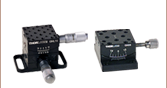
1- and 2-Axis Motorized Goniometer Stages

- Pure Rational Motion About a Fixed Point Above the Stage
- 1° Graduation Markings on Side
- Comes with Z812 DC Motors for Easy Automation
GNL20-Z8
GNL18-Z8
GNL10-Z8
Actual Cable Length
is 1.6' (0.5 m)


Please Wait

| Item # | GNL10-Z8(/M) | GNL18-Z8(/M) | GNL20-Z8(/M) |
|---|---|---|---|
| Distance to Point of Rotation |
1.00" (25.4 mm) | 1.75" (44.5 mm) | 1.00" (25.4 mm) |
| Rotation | ±8o | ±5o | ±5o / ±8o |
| Accuracy | 10 arcmin (0.167°) | 10 arcmin (0.167°) | 10 arcmin (0.167°) |
| Load Capacity | 0.50 lbs (0.227 kg) | 0.50 lbs (0.227 kg) | 0.50 lbs (0.227 kg) |
| Goniometer Dimensions (W x D x H) |
1.50" x 1.50" x 0.75" (38.1 mm x 38.1 mm x 19.1 mm) |
1.50" x 1.50" x 1.50" (38.1 mm x 38.1 mm x 38.1 mm) |
|
| Base Plate Dimensions (W x D x H) |
Imperial Goniometers: 1.50" x 2.50" x 0.20" | ||
| Metric Goniometers: 38.1 mm x 62.7 mm x 5.1 mm | |||
| Body Material | Anodized Aluminum | ||
Features
- Pure Rotational Motion About a Virtual Point
- 1° Graduation Marks on Side
- Backlash-Free Spring-Loaded Design
- Fully Lockable
- Single Axis and XY Configurations
- DC Motorized with Z812B Actuator
- Manual Goniometer Stages Also Available
A goniometer or goniometric stage is a device used to rotate an object precisely, within a small angular range, about a fixed point in space. Goniometers are similar to linear stages, but, rather than providing linear movement, the stage partially rotates about a fixed point above the mounting surface of the stage. In our two product lines, the distance from the point of rotation to the mounting surface was designed so that two different goniometer models may be stacked in an XY configuration and both stages will rotate about the same point. Our motorized goniometers use our Z812B DC Servo Actuator for enhanced, automated, angular positioning of the top plate.

Our goniometers offer unobstructed, pure rotational motion about their point of rotation over the angle of rotation (see image to the right). The compact, stackable design allows one model to be fastened to the top plate of another aligning their points of rotation. In the GNL series, the GNL10(/M) mounts atop the GNL18(/M). These two axis stage setups can be purchased as a single package [Item # GNL20(/M)] at a cost savings.
The precision dovetail design, accompanied by a backlash-free lead screw and a vernier scale, provides accurate and repeatable positioning. A side mounted setscrew can be used to lock the platform in position.
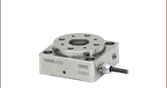
The GNL series goniometers provide an array of twelve 4-40 (M2.5) and sixteen 6-32 (M4) taps for mounting. See below for mounting hole positions.
The KDC101 DC Servo Controller is the ideal driver for the Z8 series actuators. The unit is fully compatible with our new Kinesis® software package and our legacy APT™ Control Software, both of which can be downloaded here. Please see the Motion Control Software tab for more information.
The Z812B DC servo motors shipped with these stages are provided with 1.6' (0.5 m) of cable. An 8' (2.5 m) extension cable, PAA632, is also available.

Click to Enlarge
Goniometer Dimensions

Click for Details
Mounting Options
Goniometer Specifications
| Item # | GNL10(/M) | GNL18(/M) | GNL20(/M) |
|---|---|---|---|
| Distance to Point of Rotation |
1.00" (25.4 mm) | 1.75" (44.5 mm) | 1.00" (25.4 mm) |
| Rotation | ±8o | ±5o | ±5o / ±8o |
| Accuracy | 10 arcmin (0.167°) | ||
| Load Capacity | 0.50 lbs (0.227 kg) | ||
| Goniometer Dimensions (W x D x H) |
1.50" x 1.50" x 0.75" (38.1 mm x 38.1 mm x 19.1 mm) |
1.50" x 1.50" x 1.50" (38.1 mm x 38.1 mm x 38.1 mm) |
|
| Base Plate Dimensions (W x D x H) |
Imperial Goniometers: 1.50" x 2.50" x 0.20" | ||
| Metric Goniometers: 38.1 mm x 62.7 mm x 5.1 mm | |||
| Body Material | Anodized Aluminum | ||
Z8 Actuator Specifications
| Item # | Z812B |
|---|---|
| Travel | 12 mm (0.47") |
| Motor Type | DC Servo |
| Motor Drive Voltage | 12 V |
| Max Recommended Current | 80 mA |
| Lead Screw Pitch | 1.0 mm |
| Calculated Resolution | 29 nma |
| Repeatability | <8 µm |
| Backlash (with Preload) | <8 µm |
| Feedback | Hall Effect Encoder |
| Encoder Counts per Rev. of the Lead Screw |
34,304 |
| Planetary Gearhead Ratio | 67:1 |
| Limit Switches | Electromechanical |
| Speed Range | 0.050 to 2.6 mm/s |
| Operating Temperature | 41 - 104 °F (5 - 40 °C) |
| Cable Length | 1.6' (0.5 m) |
| Compatible Controller | KDC101 |
Z812B DC Servo Motor Output
D-type Male

| Pin | Description | Pin | Description |
|---|---|---|---|
| 1 | Ground | 9 | Ident Resistor |
| 2 | Forward Limit Switch | 10 | 5 V Encoder Supply |
| 3 | Reverse Limit Switch | 11 | Encoder Channel A |
| 4 | Not Connected | 12 | Not Connected |
| 5 | Motor - | 13 | Encoder Channel B |
| 6 | Not Connected | 14 | Not Connected |
| 7 | Motor + | 15 | Not Connected |
| 8 | Not Connected |

Click to Enlarge
GNL10-Z8 Packaging

| Item # | % Weight Reduction | CO2-Equivalent Reductiona |
|---|---|---|
| GNL10-Z8 | 7.92% | 0.05 kg |
| GNL10/M-Z8 | 7.92% | 0.09 kg |
| GNL18-Z8 | 29.80% | 0.17 kg |
| GNL18/M-Z8 | 7.92% | 0.12 kg |
Smart Pack
- Reduce Weight of Packaging Materials
- Increase Usage of Recyclable Packing Materials
- Improve Packing Integrity
- Decrease Shipping Costs
Thorlabs' Smart Pack Initiative is aimed at waste minimization while still maintaining adequate protection for our products. By eliminating any unnecessary packaging, implementing packaging design changes, and utilizing eco-friendly packaging materials for our customers when possible, this initiative seeks to improve the environmental impact of our product packaging. Products listed above are now shipped in re-engineered packaging that minimizes the weight and the use of non-recyclable materials.b As we move through our product line, we will indicate re-engineered packages with our Smart Pack logo.
Thorlabs offers two platforms to drive our wide range of motion controllers: our Kinesis® software package or the legacy APT™ (Advanced Positioning Technology) software package. Either package can be used to control devices in the Kinesis family, which covers a wide range of motion controllers ranging from small, low-powered, single-channel drivers (such as the K-Cubes™ and T-Cubes™) to high-power, multi-channel, modular 19" rack nanopositioning systems (the APT Rack System).
The Kinesis Software features .NET controls which can be used by 3rd party developers working in the latest C#, Visual Basic, LabVIEW™, or any .NET compatible languages to create custom applications. Low-level DLL libraries are included for applications not expected to use the .NET framework. A Central Sequence Manager supports integration and synchronization of all Thorlabs motion control hardware.

Kinesis GUI Screen

APT GUI Screen
Our legacy APT System Software platform offers ActiveX-based controls which can be used by 3rd party developers working on C#, Visual Basic, LabVIEW™, or any Active-X compatible languages to create custom applications and includes a simulator mode to assist in developing custom applications without requiring hardware.
By providing these common software platforms, Thorlabs has ensured that users can easily mix and match any of the Kinesis and APT controllers in a single application, while only having to learn a single set of software tools. In this way, it is perfectly feasible to combine any of the controllers from single-axis to multi-axis systems and control all from a single, PC-based unified software interface.
The software packages allow two methods of usage: graphical user interface (GUI) utilities for direct interaction with and control of the controllers 'out of the box', and a set of programming interfaces that allow custom-integrated positioning and alignment solutions to be easily programmed in the development language of choice.
A range of video tutorials is available to help explain our APT system software. These tutorials provide an overview of the software and the APT Config utility. Additionally, a tutorial video is available to explain how to select simulator mode within the software, which allows the user to experiment with the software without a controller connected. Please select the APT Tutorials tab above to view these videos.
Software
Kinesis Version 1.14.25
The Kinesis Software Package, which includes a GUI for control of Thorlabs' Kinesis and APT™ system controllers.
Also Available:
- Communications Protocol
Software
APT Version 3.21.4
The APT Software Package, which includes a GUI for control of Thorlabs' APT™ and Kinesis system controllers.
Also Available:
- Communications Protocol
These videos illustrate some of the basics of using the APT System Software from both a non-programming and a programming point of view. There are videos that illustrate usage of the supplied APT utilities that allow immediate control of the APT controllers out of the box. There are also a number of videos that explain the basics of programming custom software applications using Visual Basic, LabView and Visual C++. Watch the videos now to see what we mean.
 |
Click here to view the video tutorial | |
To further assist programmers, a guide to programming the APT software in LabView is also available.
 |
Click here to view the LabView guide | |
| Posted Comments: | |
user
(posted 2020-09-13 01:03:12.25) Hi,
following the prior comment written posted on 2020-09-07 05:51:11.08, what is the distance from the lower scales to the point of rotation ?
Thanks in advance llamb
(posted 2020-09-16 03:40:45.0) Thank you for contacting Thorlabs. After discussing further by email, the radius of curvature for each goniometer's top plate is being requested when referring to the distance between the point of rotation and the scales. For the GNL20-Z8, the radius of the top plate of the top goniometer (our GNL10) is 1.623". The radius for the top plate of the bottom goniometer (our GNL18) is 2.314". user
(posted 2020-09-07 05:51:11.08) Hi,
is it possible to detail the distance between the point of rotation to the upper\lower motors scales and not only the distance from the top plate to the rotation point?
I'd like to have an exact radius of the rotation.
Thanks YLohia
(posted 2020-09-11 10:22:29.0) Hello, thank you for contacting Thorlabs. For the GNL20-Z8, the distance between the scales and the surface of the top plate is 11.159 mm. This makes the total distance between the point of rotation and scales 25.4 mm (1") + 11.159 mm = 36.559 mm. user
(posted 2020-07-06 09:00:57.407) Hi,
is there any possiblitity to set a custom home position for the GNL10/M-Z8. It would be nice to position the gonimeter to the 0 Degree position and move it from there to the required position.
Thank you.
M. llamb
(posted 2020-07-20 04:03:12.0) Hello M, thank you for contacting Thorlabs. You can use our Motion Control Software to implement your own Zero Offset through the Settings menu in the software GUI. liu chi
(posted 2019-12-04 16:07:00.39) 现在我可以用GUI来控制角位移台的运动,但我想知道我可以用命令来控制这款角位移台的运动吗?如果可以的话,有没有简易指南之类的能否提供?不胜感激 llamb
(posted 2019-12-05 07:28:23.0) Thank you for contacting Thorlabs. Our APT or Kinesis Motion Control Software can indeed be implemented in third party software for using commands to control your stage. You can find some guides under the APT Tutorials tab on this page, as well as by navigating from this link: https://www.thorlabs.com/navigation.cfm?guide_id=2251. You may also reach out to techsupport-cn@thorlabs.com directly for future technical inquiries. We have reached out to you directly in this case to discuss how you would like to send commands to your stage.
感谢您与Thorlabs联系。 实际上,我们的APT或Kinesis运动控制软件可以在第三方软件中实现,以使用命令来控制舞台。 您可以在此页面的“ APT教程”标签下找到一些指南,也可以通过以下链接导航:https://www.thorlabs.com/navigation.cfm?guide_id=2251。 您也可以直接联系techsupport-cn@thorlabs.com,以进行将来的技术咨询。 在这种情况下,我们已经直接与您联系,讨论您希望如何将命令发送到舞台。 lingxu
(posted 2016-02-10 14:38:56.31) The tilt value displayed in APT cannot be converted to rotation in radians, therefore I could not use this stage to set the tilt to a specific value. besembeson
(posted 2016-03-03 10:03:40.0) Response from Bweh at Thorlabs USA: The actuator is not calibrated with respect to the goniometer stage when we ship these systems. You will have to perform such a calibration to relate the goniometer tilt with the actuator position. I will follow-up with you to further discuss this. scott.gagnon
(posted 2014-03-18 15:59:25.32) You should list the operating temps with your spec sheets. myanakas
(posted 2014-03-19 12:40:04.0) Thank you for you feedback. Currently the operating temperature is in the specifications section of the linked manual and the "Specs" tab. The manual can be found by clicking on the red "Docs" icon next to the part numbers. |

 Zoom
Zoom Click to Enlarge
KCH601 USB Controller Hub (Sold Separately) with Installed K-Cube and T-Cube™ Modules (T-Cubes Require the KAP101 Adapter)
Click to Enlarge
KCH601 USB Controller Hub (Sold Separately) with Installed K-Cube and T-Cube™ Modules (T-Cubes Require the KAP101 Adapter)- Front Panel Velocity Wheel and Digital Display for Controlling Motorized Stages or Actuators
- Two Bidirectional Trigger Ports to Read or Control External Equipment
- Interfaces with Computer Using Included USB Cable
- Fully Compatible with Kinesis® or APT™ Software Packages
- Compact Footprint: 60.0 mm x 60.0 mm x 49.2 mm (2.42" x 2.42" x 1.94")
- Power Supply Not Included (See Below)
Thorlabs' KDC101 K-Cube Brushed DC Motor Controller provides local and computerized control of a single motor axis. It features a top-mounted control panel with a velocity wheel that supports four-speed bidirectional control with forward and reverse jogging as well as position presets. A backlit digital display is also included that can have the backlit dimmed or turned off using the top-panel menu options. The front of the unit contains two bidirectional trigger ports that can be used to read a 5 V external logic signal or output a 5 V logic signal to control external equipment. Each port can be independently configured.
The unit is fully compatible with our new Kinesis software package and our legacy APT control software. Please see the Motion Control Software tab for more information.
Please note that this controller does not ship with a power supply. Compatible power supplies are listed below. Additional information can be found on the main KDC101 DC Servo Motor Controller page.

 Zoom
Zoom
Click for Details
A location-specific adapter is shipped with the power supply unit based on your location. The adapters for the KPS101 are shown here.

Click to Enlarge
The KPS101 Power Supply Unit
- Individual Power Supply
- KPS101: For K-Cubes™ or T-Cubes™ with 3.5 mm Jacks
- USB Controller Hubs Provide Power and Communications
- KCH301: For up to Three K-Cubes or T-Cubes
- KCH601: For up to Six K-Cubes or T-Cubes
The KPS101 power supply outputs +15 VDC at up to 2.4 A and can power a single K-Cube or T-Cube with a 3.5 mm jack. It plugs into a standard wall outlet.
The KCH301 and KCH601 USB Controller Hubs each consist of two parts: the hub, which can support up to three (KCH301) or six (KCH601) K-Cubes or T-Cubes, and a power supply that plugs into a standard wall outlet. The hub draws a maximum current of 10 A; please verify that the cubes being used do not require a total current of more than 10 A. In addition, the hub provides USB connectivity to any docked K-Cube or T-Cube through a single USB connection.
For more information on the USB Controller Hubs, see the full web presentation.