 Products Home / Motion Control Electronics / Piezo / Strain Gauge Controllers / 150 V USB Closed-Loop Piezo Controllers
150 V USB Closed-Loop Piezo Controllers
- 1-Channel and 3-Channel Options
- Selectable High-Power Drive Outputs
- Front Panel Controls
BPC303
BPC301
Full Suite of Software Support Tools Included


Please Wait
| Benchtop Motion Controllers |
|---|
| 1-, 2- and 3-Channel Brushless DC Servo Controllers |
| 1-, 2-, and 3-Channel Stepper Motor Controllers |
| 1- and 3-Channel Open Loop Piezo Controllers |
| 1- and 3-Channel Closed Loop Piezo Controllers |
| 2-Channel NanoTrak® Auto-Alignment Controller |

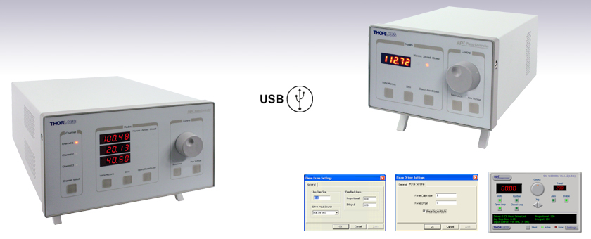
Click to Enlarge
BPC301

Click to Enlarge
BPC301 Rear Panel
Features
- Variable Output Selection: 75 V, 100 V, or 150 V
- Closed-Loop PID with Advanced Control Algorithm
- Strain Gauge or Capacitive Sensor Feedback Options
- High-Resolution Position Control for Very Fine Positioning Applications
- Voltage Ramp/Waveform Generation Capability for Scanning Applications
- High Bandwidth (10 kHz) Piezo Positioning
- Auto-Configure Function for Thorlabs Ident-Equipped Piezo Actuators
- User-Controlled Digital I/O Port
- USB Plug-and-Play – Multiaxis Expansion
- Motor Control I/O Port (Jogging, Interlocks)
- Full Software Control Suite Supplied
- Intuitive Software Graphical Control Panels
- Extensive ActiveX® Programming Interfaces
- Fully Software Integrated with Other APT™ Family Controllers (Integrated Systems Development)
These single- and 3-channel, high-power (150 V) benchtop piezo controllers provide open- or closed-loop nanometer position control. They have been designed to drive our full range of open- and closed-loop piezo-equipped nanopositioning actuators and stages. In addition, flexible software settings make these units highly configurable and therefore suitable for driving a wide range of third-party piezo elements. A waveform generation capability combined with triggering outputs make these units particularly suitable for piezo scanning applications.
Manual controls are located on the front face of the unit to allow manual adjustment of the piezo position using the digitally encoded adjustment pot. The display is easy to read and can be set to show either applied voltage or position in microns. Open- or closed-loop control and zeroing of the piezo can also be selected from the front panel.
USB connectivity provides easy plug-and-play PC operation. Multiple units can be connected to a single PC via standard USB hub technology for multi-axis motion control applications. Coupling this with the user-friendly APT™ software allows the unit to get up and running quickly. For example, all relevant operating parameters are set automatically for Thorlabs' piezo actuated products. Advanced custom motion control applications and sequences are also possible using the extensive ActiveX® programming environment, which is described in more detail on the Motion Control Software tab. These ActiveX Controls can be incorporated into a wide range of software development environments including Labview, C++, and Matlab.
| Other Piezo Driver Controllers | |||
|---|---|---|---|
| K-Cube™ Single-Channel Controller | Open Loop Benchtop Controller 1- and 3-Channel |
Closed Loop Benchtop Controller 1- and 3-Channel |
Modular 2-Channel Rack System Module |
Specifications (Per Channel)
| Item # | BPC301 | BPC303 |
|---|---|---|
| Piezoelectric Output (SMC Male) | ||
| Voltage (Software Control) | 75 V, 100 V, or 150 VDC | |
| Current | 500 mA Continuous (Max) | 1 A Continuous (Max) |
| Stability | 100 ppm Over 24 Hours (After 30 min Warm-Up Time) | |
| Noise | <3 mV RMS | |
| Piezo Capacitance | 1 to 10 µF (Typical) | |
| Bandwidth | 10 kHz (1 µF Load, 1 Vp-p) | |
| External Input (BNC) | ||
| Input Type | Differential or Single Ended | |
| Input Voltage for Full Range (i.e. 75 V, 100 V or 150 V) |
10 V ±2% | |
| Max Output | 75 V Range: -10V to 90 V DC 100 V Range: -10V to 115 V DC 150 V Range: -10 V to 159 V DC |
|
| Position Feedback (PIEZO IN) (9-Pin D-Type Female) | ||
| Feedback Transducer Typea | Strain Gauge or Capacitive Sensor | |
| Detection Method | AC Bridge (18 kHz Excitation) | |
| Typical Resolution | 5 nm (for 20 µm Actuator e.g., PAZ005) | |
| Auto Configure | Identification Resistor or Stage ID EEPROM in Actuator | |
| User Input/Output (AUX IO) (15-Pin D-Type Female) | ||
| 4 Digital Inputs | TTL Levels | |
| 4 Digital Outputs | Open Collector | |
| Trigger Input/Output | TTL | |
| Trigger Input Functionality | Triggered Voltage Ramps/Waveforms | |
| Trigger Output Functionality | Trigger Generation During Voltage Ramp Output | |
| User 5 V (with Ground) | 250 mA (Max) | |
Specifications (Main Unit)
| Item # | BPC301 | BPC303 |
|---|---|---|
| Front Panel Controls | ||
| Display | 5-Digit, 7-Segment | |
| Buttons | Channel Select, Volts/Microns Select, Open/Closed Loop Select, Zero, Resolution, Max Voltage |
|
| Display Brightness | Adjustable | |
| Resolution | Switchable Coarse and Fine Adjustment | |
| Output | Infinite Turn Precision Digital Potentiometer (Encoder) | |
| USB Port | Version 2.0 Full Speed Compatible | |
| Input Power Requirements | ||
| Voltage | 85 - 264 VAC | |
| Power | 150 VA | 250 VA |
| Fuse | 3.15 A | 3.15 A |
| General | ||
| Housing Dimensions (W x D x H) | 152 mm x 244 mm x 104 mm (6" x 9.6" x 4.1") |
240 mm x 360 mm x 133 mm (9.5" x 14.2" x 5.2") |
| Weight | 3.18 kg (7 lbs) | 6.7 kg (14.75 lbs) |
The graphs below show the drive voltage/frequency response at different capacitive loads for the BPC301 and BPC303.

Click to Enlarge
Click Here for Raw Data

Click to Enlarge
Click Here for Raw Data
Piezo In
D-Type Female

| Pin | Description | Pin | Description | Pin | Description |
|---|---|---|---|---|---|
| 1 | Strain Gauge Excitation | 4 | Ground | 7 | Actuator ID Signalb |
| 2 | +15 V Outa | 5 | AC Feedback In | 8 | Reserved for Future Use |
| 3 | -15 V Outa | 6 | Ground | 9 | Reserved for Future Use |
Interconnect
D-Type Male

| Pin | Description | Pin | Description | Pin | Description |
|---|---|---|---|---|---|
| 1 | Not Connected | 4 | Not Connected | 7 | Not Connected |
| 2 | RX (Controller Input) | 5 | Ground | 8 | Not Connected |
| 3 | TX (Controller Output) | 6 | Not Connected | 9 | Not Connected |
AUX I/O
D-Type Female

| Pin | Description | Return | Pin | Description | Return | Pin | Description | Return |
|---|---|---|---|---|---|---|---|---|
| 1 | DIG O/P 1 | 5, 9, 10 | 6 | DIG I/P 1 | 5, 9, 10 | 11 | For Future Use (Trigger OUT) | 5, 9, 10 |
| 2 | DIG O/P 2 | 5, 9, 10 | 7 | DIG I/P 2 | 5, 9, 10 | 12 | For Future Use (Trigger IN) | 5, 9, 10 |
| 3 | DIG O/P 3 | 5, 9, 10 | 8 | DIG I/P 3 | 5, 9, 10 | 13 | DIG I/P 4 | 5, 9, 10 |
| 4 | DIG O/P 4 | 5, 9, 10 | 9 | DIG Ground | - | 14 | 5 V Supply Output | 5, 9, 10 |
| 5 | DIG Ground | - | 10 | DIG Ground | - | 15 | 5 V Supply Output | 5, 9, 10 |
Handset In

| Pin | Description | Pin | Description |
|---|---|---|---|
| 1 | RX (Controller Input) | 4 | +5 V, 100 mA Supply for Joystick |
| 2 | Ground | 5 | TX (Controller Output) |
| 3 | Ground | 6 | Ground |
USB
B-Type Female

HV Out
Male SMC

Output Voltage: 0 - 150 V
Current: 0 - 500 mA
Trig In and Trig Out
BNC Connectors

Input Trig Voltage: 0 - 7 V DC
Output Trig Voltage: 0 - 5 V DC
EXT In (+) and EXT In (-)
BNC Female
Input Voltage: 0 - 10 V
Input Impedance: 20 kΩ
Flexibility

The BPC300 Series are the latest generation piezo controllers to be added to the apt™ motion control family. They have been designed for use in critical alignment applications where manual or automated nanometer level motion control is required. These high power yet low noise units deliver up to 150 V per channel and are compatible with all piezo-actuated nanopositioning actuators and stages in the Thorlabs range. They combine the latest high speed digital signal processors (DSP) with low-noise analog electronics and ActiveX® software technology for effortless software controlled piezo motion.
To support such a wide range piezo actuators these apt™ piezo units are fully configurable through software accessable key parameter settings. Intuitive easy to use software graphical panels allow immediate control and visualization of the operation of the piezo controller – adjustment of many key parameters is possible through direct interaction with the graphical panel. Open or closed loop operating modes can be selected 'on the fly', and in both modes the display can be changed to show drive voltage or position (in microns). In the closed loop operation mode, both the P & I (proportional and integral) components of the feedback control loop can be altered to adjust the servo loop response. The output drive voltage or position can be adjusted by rotating the software-pane" control knob.
Note that all such settings and parameters are also accessible through the ActiveX programmable interfaces which allow the user to build automated alignment routines. Refer to the Motion Control Software tab for further information on the apt™ software support for the BPC200 Series.
Waveform Output/Triggering
Over and above open and closed loop piezo positioning the DSP controllers within the BCP300 Series offer additional and useful functionality. Through software it is possible to program in a voltage (or position) ramp or waveform as a table of values and then instruct the controller to output (clock out) this table either 'single shot' or continuously. It is possible to specify a hardware output trigger to be generated at a specific point during the waveform output in order to control third party equipment as a function of the piezo voltage (position). Alternatively an external system can trigger the piezo unit to initiate the waveform output in the reverse scenario. This functionality is particularly useful for piezo scanning applications.
Full Software GUI Control Suite & ActiveX® Controls Included

A full and sophisticated software support suite is supplied with the BPC300 controller. The suite includes a number of out of the box user utilities to allow immediate operation of the unit without any detailed pre-configuration. All operating modes can be accessed manually and all operating parameters changed and saved for next use. For more advanced custom motion control applications, a fully featured ActiveX® programming environment is also included to facilitate custom application development in a wide range of programming environments. Note that all such settings and parameters described above are also accessible through these ActiveX® programmable interfaces. For further information on the apt™ software support for the BPC300 units refer to the Motion Control Software tab. Demonstration videos illustrating how to program the apt™ software are also available for viewing.
The ActiveX® apt™ system software shipped with these units is also compatible with other apt™ family controllers including our multi-channel rack-based system and smaller optical table mountable 'Cube' controllers. This single unified software offering allows seamless mixing of any apt™ benchtop, table top and rack based units in any single positioning application.
The key innovation of the apt™ range of controllers and associated mechanical products is the ease and speed with which complete automated alignment/positioning systems can be engineered at both the hardware and software level. All controllers in the apt™ range are equipped with USB connectivity. The 'multi-drop' USB bus allows multiple apt™ units to be connected to a single controller PC using commercial USB hubs and cables. When planning a multichannel application, simply add up the number and type of drive channels required and connect together the associated number of APT controllers.
Software Developers Support CD
A developers’ kit is shipped with all of our apt™ series controllers. This additional software support is intended for use by software developers working on large, system integration projects that incorporate apt™ products. The kit contains an extensive selection of useful code samples as well as a library of Video Tutorials.
Thorlabs offers two platforms to drive our wide range of motion controllers: our Kinesis® software package or the legacy APT™ (Advanced Positioning Technology) software package. Either package can be used to control devices in the Kinesis family, which covers a wide range of motion controllers ranging from small, low-powered, single-channel drivers (such as the K-Cubes™ and T-Cubes™) to high-power, multi-channel, modular 19" rack nanopositioning systems (the APT Rack System).
The Kinesis Software features .NET controls which can be used by 3rd party developers working in the latest C#, Visual Basic, LabVIEW™, or any .NET compatible languages to create custom applications. Low-level DLL libraries are included for applications not expected to use the .NET framework. A Central Sequence Manager supports integration and synchronization of all Thorlabs motion control hardware.

Kinesis GUI Screen

APT GUI Screen
Our legacy APT System Software platform offers ActiveX-based controls which can be used by 3rd party developers working on C#, Visual Basic, LabVIEW™, or any Active-X compatible languages to create custom applications and includes a simulator mode to assist in developing custom applications without requiring hardware.
By providing these common software platforms, Thorlabs has ensured that users can easily mix and match any of the Kinesis and APT controllers in a single application, while only having to learn a single set of software tools. In this way, it is perfectly feasible to combine any of the controllers from single-axis to multi-axis systems and control all from a single, PC-based unified software interface.
The software packages allow two methods of usage: graphical user interface (GUI) utilities for direct interaction with and control of the controllers 'out of the box', and a set of programming interfaces that allow custom-integrated positioning and alignment solutions to be easily programmed in the development language of choice.
A range of video tutorials is available to help explain our APT system software. These tutorials provide an overview of the software and the APT Config utility. Additionally, a tutorial video is available to explain how to select simulator mode within the software, which allows the user to experiment with the software without a controller connected. Please select the APT Tutorials tab above to view these videos.
Software
Kinesis Version 1.14.25
The Kinesis Software Package, which includes a GUI for control of Thorlabs' Kinesis and APT™ system controllers.
Also Available:
- Communications Protocol
Software
APT Version 3.21.4
The APT Software Package, which includes a GUI for control of Thorlabs' APT™ and Kinesis system controllers.
Also Available:
- Communications Protocol
These videos illustrate some of the basics of using the APT System Software from both a non-programming and a programming point of view. There are videos that illustrate usage of the supplied APT utilities that allow immediate control of the APT controllers out of the box. There are also a number of videos that explain the basics of programming custom software applications using Visual Basic, LabView and Visual C++. Watch the videos now to see what we mean.
 |
Click here to view the video tutorial | |
To further assist programmers, a guide to programming the APT software in LabView is also available.
 |
Click here to view the LabView guide | |
Piezo Driver Bandwidth Tutorial
Knowing the rate at which a piezo is capable of changing lengths is essential in many high-speed applications. The bandwidth of a piezo controller and stack can be estimated if the following is known:
- The maximum amount of current the controllers can produce. This is 0.5 A for our BPC Series Piezo Controllers, which is the driver used in the examples below.
- The load capacitance of the piezo. The higher the capacitance, the slower the system.
- The desired signal amplitude (V), which determines the length that the piezo extends.
- The absolute maximum bandwidth of the driver, which is independent of the load being driven.
To drive the output capacitor, current is needed to charge it and to discharge it. The change in charge, dV/dt, is called the slew rate. The larger the capacitance, the more current needed:

For example, if a 100 µm stack with a capacitance of 20 µF is being driven by a BPC Series piezo controller with a maximum current of 0.5 A, the slew rate is given by

Hence, for an instantaneous voltage change from 0 V to 75 V, it would take 3 ms for the output voltage to reach 75 V.
Note: For these calculations, it is assumed that the absolute maximum bandwidth of the driver is much higher than the bandwidths calculated, and thus, driver bandwidth is not a limiting factor. Also please note that these calculations only apply for open-loop systems. In closed-loop mode, the slow response of the feedback loop puts another limit on the bandwidth.
Sinusoidal Signal

The bandwidth of the system usually refers to the system's response to a sinusoidal signal of a given amplitude. For a piezo element driven by a sinusoidal signal of peak amplitude A, peak-to-peak voltage Vpp, and frequency f, we have:

A diagram of voltage as a function of time is shown to the right. The maximum slew rate, or voltage change, is reached at t = 2nπ, (n=0, 1, 2,...) at point a in the diagram to the right:

From the first equation, above:

Thus,
For the example above, the maximum full-range (75 V) bandwidth would be
 .
.
For a smaller piezo stack with 10 times lower capacitance, the results would be 10 times better, or about 1060 Hz. Or, if the peak-to-peak signal is reduced to 7.5 V (10% max amplitude) with the 100 µm stack, again, the result would be 10 times better at about 1060 Hz.

Triangle Wave Signal
For a piezo actuator driven by a triangle wave of max voltage Vpeak and minimum voltage of 0, the slew rate is equal to the slope:
![]() .
.
Or, since f = 1/T:


Square Wave Signal
For a piezo actuator driven by a square wave of maximum voltage Vpeak and minimum voltage 0, the slew rate limits the minimum rise and fall times. In this case, the slew rate is equal to the slope while the signal is rising or falling. If tr is the minimum rise time, then

or
 .
.
For additional information about piezo theory and operation, see the Piezoelectric Tutorials page.
| Posted Comments: | |
user
(posted 2020-10-14 17:35:59.51) Excuse me,could i change the output voltage frequency when i use the BPC301, and output a high frequency voltage? cwright
(posted 2020-10-14 08:23:59.0) Response from Charles at Thorlabs: Hello and thank you for contacting us. The output voltage (open loop) or position of the piezo actuator(closed loop) can be controlled from an external source via the EXT IN (+) and EXT IN (-) BNC connectors on the rear panel. The exact bandwidth achievable is dependent on a variety of factors, such as the load capacitance but in general is a few kHz in open loop mode and about 200 Hz in closed loop.
For more details on configuring the EXT IN connections please see section 3.3 of the manual and the Piezo Bandwidth tutorial on the website:
https://www.thorlabs.com/NewGroupPage9.cfm?ObjectGroup_ID=1912&tabname=Piezo%20Bandwidth agarciat
(posted 2017-09-08 14:07:34.203) Dear Thorlabs. We have got your BPC 301 controller . The problem is that the controller does not change the voltage and the position neither by the front panel nor by the software.I keep getting an internal error#16510403/Error; [Code=1252] power supply error. The front panel shows 0.60V and when turned onto closed it continues to oscillate +/-0.05 or so. As it oscillates, in the APT User window I get a new window every second with the same error. How do I increase the voltage? Please advise on possible solution. bwood
(posted 2017-09-26 04:37:04.0) Response from Ben at Thorlabs: I am sorry to hear about your issues here. I believe this may be a fault with your device, and we will be in contact to troubleshoot this issue further. jedd
(posted 2017-08-11 12:23:55.113) Is it possible to use this PZT controller to specify applied force over time instead of displacement over time? bwood
(posted 2017-08-18 05:17:13.0) Response from Ben at Thorlabs: Thank you for your question. The BPC has a force sensing mode, based on the the strain gauge feedback. You can configure the device for this in APT/Kinesis. One example of this functionality is with the FSC102. There is no way to directly output the force output by the piezo, but you could calculate it, see the piezo tutorial here: https://www.thorlabs.com/newgrouppage9.cfm?objectgroup_id=5030 user
(posted 2016-04-13 12:48:12.44) Is it possible to use this controller in closed loop (piezo stage+strain gauge) to eliminate hysteresis and at the same scan the stage with an external function generator? besembeson
(posted 2016-04-14 01:41:46.0) Response from Bweh at Thorlabs USA: Yes this is possible. Note that the bandwidth will be lower under this condition. g.w.steen
(posted 2015-07-23 09:02:01.35) While the controller works perfectly fine manual and with the delivered APT software, we have some difficulties using Labview. The correct ActiveX control for the ThorLabs BPC303 APT Piezo Contoller is used ('MGPiezo') and we used the SN given by the APT software. The Labview is configured as given by examples files. However still Labview returnes the error: "Control HW Communications Disabled
"
We also try selecting user interface as preferred execution stystem under File >> VI Properties >>Execution tab. Are we missing something obvious? msoulby
(posted 2015-07-28 07:01:10.0) Response from Mike at Thorlabs: We will contact you directly to trouble shoot your problem further. sylvain.girard
(posted 2014-12-05 12:30:14.847) I am currently using a BPC 203 controller with Nanomax 311 and also with APB 301 translation stages. However, I would like to purchase a new 3 axis translation stage with larger scale (and possibly a better linearity). No piezo stage with large range are available anymore in Thorlabs catalogue (with a dynamic range up to 100-300µm). Therefore, I wonder if it would be possible to use third party translation stages (for example from PI or PiezoJena or others...) while keeping the Thorlabs controller beacause I already spend a lot of time developping LabVIEW software for BPC203 controller. If I need a BPC303 (150V) that could be possible... msoulby
(posted 2014-12-08 03:52:54.0) Response from Mike at Thorlabs: At this time Thorlabs does not have a 3 axis stage with 100-300um of piezo travel. However there is no reason why the controller would not work with a third party piezo providing the piezo falls within the drive voltage specification of the controller, which is 0-75V and 500mA per channel for the BPC203. However please bear in mind that Thorlabs piezo stages that have strain gauge feedback use an auto ID resistor to tell the controller how much travel the piezo stack has and selects the correct voltage range accordingly (not applicable to open loop control and piezos) this may not be available on a third party stage so it may need to be configured manually. Also as any thir party stage will not have been tested by Thorlabs we would be unable to guarantee the stage will operate to the spec that the competitor claims and would not be responsible for any damage caused by using such a third party stage. palmada
(posted 2013-01-28 02:39:04.603) Hello, we are interested in getting this controller to drive the piezos on the nanoMax300. Will this work with MicroManager 64bits?
Best,
Pedro Almada jlow
(posted 2013-01-18 12:25:00.0) Response from Jeremy at Thorlabs: We do not have a comprehensive tutorial for VB 2010 at the moment. I will get in touch with you directly with some instructions and screenshots on using the APT software with VB 2010. branderson
(posted 2013-01-18 10:30:57.933) Hi, I have a BPC301 and have been using labview to run it, but would now like to use visual basic. We have VB 2010, which is way different than VB6 so the tutorial isn't very helpful. Do you have updated programming instructions for use with VB 2010? tcohen
(posted 2012-10-04 15:45:00.0) Response from Tim at Thorlabs to Diego: Thank you for contacting us. We have a variety of 50mm travel stages. One example which may be of interest to you is the LNR50SE. This stage utilizes a submicron resolution optical encoder to provide a direct readout of the absolute position. I will contact you directly to discuss your application in more depth. jlow
(posted 2012-09-27 09:13:00.0) Response from Jeremy at Thorlabs: We will get in contact with you directly on troubleshooting this. dgiraldo
(posted 2012-09-26 21:54:13.0) Dear ThorLabs:
I would like to get info about a XY stage (50 mm travel), with the maximun accuracy (nm), I will use the stage to measure parts metalic or plastic, I am offering dimensional metrology services in Costa Rica and I will like offer to my customers the maximun accuracy into a micron.
I need to get the value of the stage trace in mm, micron, or nm oirectly to my PC!! Is it possible?
Rgds,
Diego Giraldo
METRIX
Costa Rica leonid_krivitskiy
(posted 2012-09-21 03:00:19.0) Dear Thorlabs. We have got your BPC 203 controller along with the Nanomax TS stage. The problem is that channel no.1 of the controller does not change the voltage and the position neither by the front panel nor by the software. The front panal shows -12.3 V irrespective of the position of turning knob and the zeroing button. Other two channels are okay. Please advise on possible solution. jjurado
(posted 2011-06-15 09:02:00.0) Response from Javier at Thorlabs to last poster: Thank you very much for your feedback. We have added the piezo drive cables as related products to the pages for the BPC controllers and the NanoMax stages. We will also add a information on the Features section of these products to make it clear that the drive cables are not included with the controller, but are included with the stages. Please contact us at techsupport@thorlabs.com if you have any further questions or comments. user
(posted 2011-06-14 10:18:32.0) It would be useful to add the drive/feedback cables as a related product for either this page or the NanoMax pages. As of now, it is very unclear as to whether these are included with the controller, the stage, or not at all. apalmentieri
(posted 2010-03-03 10:41:09.0) A response to sylvain from Adam at Thorlabs: We have already responded to you via email, but wanted to update the response on our website as well. Since this feedback, We have looked into our supply of USB cables and have insured that they are all certified high speed USB cables. Currently, we do not have a complete software solution for non Active X users, but we do offer a low level comms protocol document for customer that want to program their own non Active X based software. We expect to add the piezo protocols to this document in the upcoming weeks. sylvain.girard
(posted 2009-11-21 08:01:10.0) I recently start using BPC203 with MAX313 to control scanning near field microscope and i have two comments:
- first, the USB port of the controllers needs good quality USB A/USB B cable to avoid problems (I spent few times to discover that some troubles in the communication were due to the cable...)
- it is sad that Thorlabs could not provide solutions other than Active X for programmers who prefer to develop their codes under Linux. Any solutions in this case??
Best regards klee
(posted 2009-07-17 15:17:54.0) A response from Ken at Thorlabs to noah: We do have some tutorial videos on APT Programming using Visual Basic. Simply click on the Video Tutorials tab on this page, click "here", then click on APT programming. noah
(posted 2009-07-17 13:40:12.0) Hi, I am new to visual basic, though I have extensive programming experience in other languages. I am having trouble writing vb6 code to control my BPC202 and my BPS 103. Structuring the code and calling procedures from the included libraries to create timing-sensitive & predictable object-oriented programs is rather difficult in VB, as I find myself having to guess how VB6 will sequentially execute a program, modify variables in "real time" etc.
I would like from you, if possible, a version of the apt-server.hlp file compiled into a printable .pdf or something similar (rather than printing every topic individually). Better yet, a more descriptive yet concise introduction to scientific computing with VB (via Thorlabs APT products) would be a lifesaver.
It would also be great if you had a repository of code that users could submit to and draw from as a learning tool; even if the code were not checked for bugs or vouched for by Thorlabs, it might help to see how others structure their programs.
Any old help files or internally developed VB code snippets (the included examples are a good start) that youd be willing to share with me would be great, too. Laurie
(posted 2009-02-05 17:18:02.0) Response from Laurie at Thorlabs to melsscal: Thank you for your interest in our BPC203 controller. To control the piezos on the MAX313/M, you can use the BPC203 controller. Other options include the BNT001 and the TPZ001. Please let us know if you have additional questions. melsscal
(posted 2009-02-05 03:47:58.0) Can we use BPC203 with MAX313/M as Non Track Controller ? acable
(posted 2007-10-18 07:47:11.0) PHS101 remote control device is missing from this presenation (not even posted as a related product), i would add this right into the current presentation in summary with a link to the PHS01 product page. Ideally i would like to be able to order both products from this page. |

 Zoom
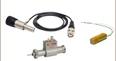
Zoom- High Reliability Hall Effect Finger Joystick
- Speed Adjustment for Fast or High Precision Moves
- Speed Pot for Sensitivity Adjustment
- Allows Remote Manual Control
- Can be Reprogrammed using a Benchtop Controller and a PC
- Ergonomic and Elegant Design
- High Quality Machined Anodized Aluminum Casing
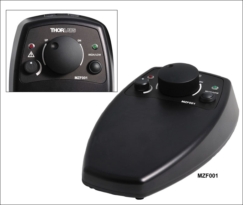
The MZF001 joystick console has been designed to provide intuitive, tactile, manual positioning of our range of piezo-based stages. It is used in conjunction with the single- and 3-channel controllers described above, enabling full control of the piezo actuators in situations where the application is at some distance from the controller, thereby allowing convenient adjustment of the output while monitoring the alignment. This is useful when working in a complex optical setup, where access to the front panel controls or adjusting controls on the PC is impractical. Furthermore, if the parameter settings are saved (persisted) to the controller, the controller need not be connected to a host PC, thereby allowing remote operation.