 Products Home
Heater Controller
- Heating from 20 - 200 °C
- User Selectable Display Units (°F, °C, or K)
- Programmable Ramp and Soak Cycles
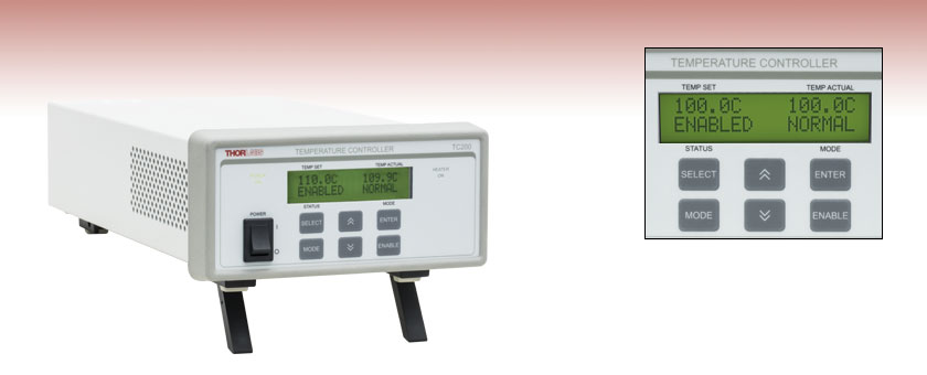
TC200
LCD Detail


Please Wait

Click to Enlarge
The TC200 Heater Controller GUI is available on the Software tab.
Features
- Heating from 20 °C to 200 °C
- User-Selectable Display Units (°F, °C, or K)
- Run Standalone or via Software
- Adjustable PID
- Compatible with Positive and Negative Temperature Coefficient Thermistors
The TC200 Heater Controller is a benchtop controller intended for use with resistive heating elements rated up to 18 W. This general-purpose instrument can drive various types of heaters, including foil (HT10K) and resistive coil (HT15W) types. The unit accepts feedback from either positive (TH100PT) or negative (TH10K) temperature coefficient thermistors, has programmable P, I, and D gains, and will display the temperature in either °F, °C, or K. In addition, the TC200 can be programmed for up to five sequential temperature settings along with associated ramp and hold times for each level. A user programmable maximum temperature limit provides protection to the device being heated and a user-programmable power limit protects the heating element from being over driven. Other safety features include an Open Sensor Alarm that will shut down the driver if the temperature sensing element is missing or becomes disconnected.
Capable of stand-alone operation from a simple keypad interface, the TC200 can be interfaced with a PC using a standard USB Type B connector and our TC200 Application Program, shown in the image to the right. Interfacing with a PC can also be achieved by using LabVIEW or LabWindows with a simple command-line interface from any terminal window.
Please note that the cable for connecting this heater controller to a heating element is not provided. The TC200 uses a Hirose connector to read the temperature of the heating element and supply current. For the pin assignments needed to adapt the TC200 to your heater, please see the Pin Diagrams tab.
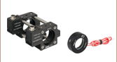
The unit also includes an auxiliary output for use with our GCH25-75 Glass Cell Heater. This auxiliary connection provides an unregulated output current that is proportional to the current supplied by the main output. Please see chapter 11 of the TC200 manual for more details about this feature. These outputs may also be used with other heater pairs, for instance when using two GCH25R cap heaters with a glass cell.
The TC200 is shipped with a 120 VAC power cord for use in the US while the TC200-EC is shipped with a 230 VAC power cord for use in Europe. If you require a power cord for another country, please contact your local sales office.

Click to Enlarge
Front Panel of the TC200 Heater Controller

Click to Enlarge
Back Panel of the TC200 Heater Controller
| TC200 Specifications | |||
|---|---|---|---|
| Thermal Specifications | Min | Typ. | Max |
| Temperature Control Rangea | 20.0 °C | - | 200.0 °C |
| Set-point Resolution | 0.1 °C | - | - |
| Actual Temperature Display Accuracyb | - | ±0.1 °C | ±0.5 °C |
| Temperature Stability, 24-hourc | - | ±0.1 °C | - |
| Electrical Specifications | Min | Typ. | Max |
| Input Voltaged | 100 VAC | - | 240 VAC |
| Input Power | - | - | 25 VA |
| Output Power | - | - | 18 W DC |
| Output Current | - | - | 0.75 ADC |
| Output Voltage | - | - | 24 VDC |
| Sensor Types | Platinum 100 Ω, Platinum 1000 Ω, NTC 10 KΩ |
||
| Output Connector | HIROSE HR10A-7R-6S | ||
| Mating Connector | HIROSE HR10A-7P-6P (73) | ||
| USB Interface | USB 2.0, Type B Plug | ||
| General Specifications | |||
| Operating Temerature | 10 - 40 °C | ||
| Storage Temperature | 0 - 50 °C | ||
| Dimensions (W x H x L) | 153.5 mm x 81.8 mm x 299.4 mm (6.04" x 3.22" x 11.79") |
||
| Weight | 5 lbs (2.3 kg) | ||
PID Basics
The PID circuit is often utilized as a control loop feedback controller and is very commonly used for many forms of servo circuits. The letters making up the acronym PID correspond to Proportional (P), Integral (I), and Derivative (D), which represents the three control settings of a PID circuit. The purpose of any servo circuit is to hold the system at a predetermined value (set point) for long periods of time. The PID circuit actively controls the system so as to hold it at the set point by generating an error signal that is essentially the difference between the set point and the current value. The three controls relate to the time-dependent error signal; at its simplest, this can be thought of as follows: Proportional is dependent upon the present error, Integral is dependent upon the accumulation of past error, and Derivative is the prediction of future error. The results of each of the controls are then fed into a weighted sum, which then adjusts the output of the circuit, u(t). This output is fed into a control device, its value is fed back into the circuit, and the process is allowed to actively stabilize the circuit’s output to reach and hold at the set point value. The block diagram below illustrates very simply the action of a PID circuit. One or more of the controls can be utilized in any servo circuit depending on system demand and requirement (i.e., P, I, PI, PD, or PID).

Through proper setting of the controls in a PID circuit, relatively quick response with minimal overshoot (passing the set point value) and ringing (oscillation about the set point value) can be achieved. Let’s take as an example a temperature servo, such as that for temperature stabilization of a laser diode. The PID circuit will ultimately servo the current to a Thermo Electric Cooler (TEC) (often times through control of the gate voltage on an FET). Under this example, the current is referred to as the Manipulated Variable (MV). A thermistor is used to monitor the temperature of the laser diode, and the voltage over the thermistor is used as the Process Variable (PV). The Set Point (SP) voltage is set to correspond to the desired temperature. The error signal, e(t), is then just the difference between the SP and PV. A PID controller will generate the error signal and then change the MV to reach the desired result. If, for instance, e(t) states that the laser diode is too hot, the circuit will allow more current to flow through the TEC (proportional control). Since proportional control is proportional to e(t), it may not cool the laser diode quickly enough. In that event, the circuit will further increase the amount of current through the TEC (integral control) by looking at the previous errors and adjusting the output in order to reach the desired value. As the SP is reached [e(t) approaches zero], the circuit will decrease the current through the TEC in anticipation of reaching the SP (derivative control).
Please note that a PID circuit will not guarantee optimal control. Improper setting of the PID controls can cause the circuit to oscillate significantly and lead to instability in control. It is up to the user to properly adjust the PID gains to ensure proper performance.
PID Theory
The output of the PID control circuit, u(t), is given as

where
Kp= Proportional Gain
Ki = Integral Gain
Kd = Derivative Gain
e(t) = SP - PV(t)
From here we can define the control units through their mathematical definition and discuss each in a little more detail. Proportional control is proportional to the error signal; as such, it is a direct response to the error signal generated by the circuit:

Larger proportional gain results is larger changes in response to the error, and thus affects the speed at which the controller can respond to changes in the system. While a high proportional gain can cause a circuit to respond swiftly, too high a value can cause oscillations about the SP value. Too low a value and the circuit cannot efficiently respond to changes in the system.
Integral control goes a step further than proportional gain, as it is proportional to not just the magnitude of the error signal but also the duration of the error.

Integral control is highly effective at increasing the response time of a circuit along with eliminating the steady-state error associated with purely proportional control. In essence integral control sums over the previous error, which was not corrected, and then multiplies that error by Ki to produce the integral response. Thus, for even small sustained error, a large aggregated integral response can be realized. However, due to the fast response of integral control, high gain values can cause significant overshoot of the SP value and lead to oscillation and instability. Too low and the circuit will be significantly slower in responding to changes in the system.
Derivative control attempts to reduce the overshoot and ringing potential from proportional and integral control. It determines how quickly the circuit is changing over time (by looking at the derivative of the error signal) and multiplies it by Kd to produce the derivative response.

Unlike proportional and integral control, derivative control will slow the response of the circuit. In doing so, it is able to partially compensate for the overshoot as well as damp out any oscillations caused by integral and proportional control. High gain values cause the circuit to respond very slowly and can leave one susceptible to noise and high frequency oscillation (as the circuit becomes too slow to respond quickly). Too low and the circuit is prone to overshooting the SP value. However, in some cases overshooting the SP value by any significant amount must be avoided and thus a higher derivative gain (along with lower proportional gain) can be used. The chart below explains the effects of increasing the gain of any one of the parameters independently.
| Parameter Increased | Rise Time | Overshoot | Settling Time | Steady-State Error | Stability |
|---|---|---|---|---|---|
| Kp | Decrease | Increase | Small Change | Decrease | Degrade |
| Ki | Decrease | Increase | Increase | Decrease Significantly | Degrade |
| Kd | Minor Decrease | Minor Decrease | Minor Decrease | No Effect | Improve (for small Kd) |
Tuning
In general the gains of P, I, and D will need to be adjusted by the user in order to best servo the system. While there is not a static set of rules for what the values should be for any specific system, following the general procedures should help in tuning a circuit to match one’s system and environment. In general a PID circuit will typically overshoot the SP value slightly and then quickly damp out to reach the SP value.
Manual tuning of the gain settings is the simplest method for setting the PID controls. However, this procedure is done actively (the PID controller turned on and properly attached to the system) and requires some amount of experience to fully integrate. To tune your PID controller manually, first the integral and derivative gains are set to zero. Increase the proportional gain until you observe oscillation in the output. Your proportional gain should then be set to roughly half this value. After the proportional gain is set, increase the integral gain until any offset is corrected for on a time scale appropriate for your system. If you increase this gain too much, you will observe significant overshoot of the SP value and instability in the circuit. Once the integral gain is set, the derivative gain can then be increased. Derivative gain will reduce overshoot and damp the system quickly to the SP value. If you increase the derivative gain too much, you will see large overshoot (due to the circuit being too slow to respond). By playing with the gain settings, you can maximize the performance of your PID circuit, resulting in a circuit that quickly responds to changes in the system and effectively damps out oscillation about the SP value.
| Control Type | Kp | Ki | Kd |
|---|---|---|---|
| P | 0.50 Ku | - | - |
| PI | 0.45 Ku | 1.2 Kp/Pu | - |
| PID | 0.60 Ku | 2 Kp/Pu | KpPu/8 |
While manual tuning can be very effective at setting a PID circuit for your specific system, it does require some amount of experience and understanding of PID circuits and response. The Ziegler-Nichols method for PID tuning offers a bit more structured guide to setting PID values. Again, you’ll want to set the integral and derivative gain to zero. Increase the proportional gain until the circuit starts to oscillate. We will call this gain level Ku. The oscillation will have a period of Pu. Gains are for various control circuits are then given below in the chart.
Main and Auxillary Output Connectors
HIROSE HR10A-7R-6S

This view of the connectors is as seen from the rear panel.
| Pin | Assignment |
|---|---|
| 1 | Heater Output Positive |
| 2 | Heater Output Return (Ground) |
| 3 | Reserved (Do not Connect to this Pin) |
| 4 | Sensor Input (+) |
| 5 | Sensor Input (Ground) |
| 6 | Reserved (Do not Connect to this Pin) |
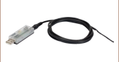
Computer Connection
USB Type B

USB Type B to Type A Cable Included
The TC200 is compatible with PT100 (Item # TH100PT) and PT1000 types of Platinum Thermistors, as well as the TH10K thermistor. The following specifications are used for determining the set-point and read back values for these types of thermistors.
PT100 and PT1000 Sensors
For the temperature range of 0 to 850 °C:
RT = R0 (1 + AT + BT2)
(In accordance with IEC 751, 2:1995-07 [DIN EN 60751; 1996-07])
A = 3.9083 x 10⁻³ °C-1
B = -5.775 x 10⁻⁷ °C-2
RT is the resistance in Ω at temperature T
T is the temperature in °C
R0 = 100 Ω for the PT100
R0 = 1000 Ω for the PT1000
TH10K Sensor
RT = 10000expβ[(1/T) - (1/298)]
RT is the resistance in Ω at temperature T
T is the temperature in K
β is the constant associated with the particular thermistor
Software for the TC200 Heater Controller
Software
Version 1.6.0
Software package to operate the TC200 including a GUI, drivers, and LabVIEW™/C++ SDK for third-party development.
| Posted Comments: | |
豪彬 林
(posted 2020-09-16 21:54:28.59) 该产品的labview 示例无法连接到仪器 YLohia
(posted 2020-09-16 10:50:25.0) Thank you for contacting Thorlabs. An applications engineer from our team in China (techsupport-cn@thorlabs.com) will reach out to you directly. JInwoo Kim
(posted 2020-07-16 04:33:47.827) I have few TC200. And I want to treat this by computer. But I'm only familiar with MATLAB, not Labview. So could you send me some matlab example code or MATLAB commands of TC200? It will be good for me if there is some MATLAB manual documents for TC200.
Thanks
Best regards, asundararaj
(posted 2020-07-17 09:30:45.0) Thank you for your feedback. We offer libraries for programming in C++ that are included in the installation of the software. For use in Matlab, you will need to wrap the TC200_COMMAND_LIB_win32.dll into a MEX file. This would allow you to call C/C++ functions from Matlab. Another option would be to use the Serial Commands for the controller and send these using the Matlab serialport library. Please note that we do not offer formal Matlab support. That being said, I have reached out to you directly to discuss this further. Nevin Brosius
(posted 2020-07-09 18:22:26.29) I am interested in purchasing this product but the software is limited by the five separate temperature settings. It would be ideal if there were more temperature settings. For example, going from 20 to 30C in discrete steps of 0.1C and remaining at each temperature for 10 minutes. I would appreciate contact if there is a solution to this problem. Thanks for the help. The customer service has been very good. YLohia
(posted 2020-07-13 09:41:50.0) Thank you for contacting Thorlabs and your feedback regarding our customer service. The five-cycle limit is a limitation of the hardware and, unfortunately, it is not possible to set more than five steps from the GUI. You can, however, set a step size of >= 0.1 for the temperatures. Additional temperature cycles can be incorporated by creating your own program in LabVIEW, C++, etc. Don Yuan
(posted 2020-06-08 02:22:16.083) Hello, abou the heater controller, is there any higher T-limit one? for example 350C?
Thank you. asundararaj
(posted 2020-06-08 05:34:41.0) Thank you for contacting Thorlabs. We currently do not offer a higher temperature limit option for the heater controllers. Rajni Bala
(posted 2019-12-12 23:34:39.45) I am from IIT Delhi I had purchased TC200 for gas cell heater GCH25-75. I set my Tset=40 C, Tact=39.8-39.9 C; but, I found that heating is comparatively lower. It's not heating properly. Can you suggest anything about how to improve it? asundararaj
(posted 2020-01-02 01:18:04.0) Thank you for contacting Thorlabs. I have reached out to you via email to troubleshoot. abhimicro
(posted 2019-01-27 03:34:55.14) Dear Thorlabs, I want to set up a hot plat to work for temperature range from 20 C - 200C with a precision of 2deg C. As I understand, I need 3 items to do this.
(1) TC200, (2) Temperature sensor, (3) Heating coils.
My questions are:
(1) Is temperature sensor supplied with TC 200?
(2) If I understand correctly, temperature sensor will be placed near the coil and it should be input to TC 200. Right?
(3) The program to control this from a computer will be provided with TC200.
Thanks
Abhishek YLohia
(posted 2019-01-30 09:00:40.0) Hello Abhishek, thank you for contacting Thorlabs.
1) No, the temperature sensor is not supplied with the controller. You can purchase one (for example the TH10K) that fits your needs from this page : https://www.thorlabs.com/newgrouppage9.cfm?objectgroup_id=305&pn=TH10K
2) The thermistor should be placed in thermal contact with the device you're monitoring the temperature of, which is the hot plate in your specific case. Yes, this will be fed in to the TC200C.
3) The software is provided with this and can be found here : https://www.thorlabs.com/software_pages/ViewSoftwarePage.cfm?Code=TC200 shiwenzhong1989
(posted 2018-09-29 17:41:10.543) Dear Thorlabs,could the TC200-EC control temperature lower than 20℃?For example,my chip is -60℃ in the begining,and i want to set the setpoint to -50℃,does it work? YLohia
(posted 2018-10-02 10:11:14.0) Hello, thank you for contacting Thorlabs. Unfortunately, the control range of the TC200 is limited to 20 C - 200 C. It cannot be operated below 20 C. sergio.vilches
(posted 2018-07-13 11:20:56.073) Dear Thorlabs,
This device is not suitable for automated temperature control due to an error in the implementation of the PID algorithm on the firmware: It seems that the PID implementation is missing the Anti-Windup, creating a constant steady-state error.
The TUNE function sometimes helps to reduce this error, but it is not reliable enough for automated measurements.
Please feel free to contact me for further details and usability tips. YLohia
(posted 2018-07-17 09:39:38.0) Hello, thank you for your feedback. We are aware of these limitations to the TC200 and are working on a redesign, though we do not have a release date yet. We do have plans to move the PID control into the firmware instead of the hardware as it is now. When this was originally developed there was only rudimentary control through the serial port as this wasn’t really intended to be an automated device. That being said, we are starting the preliminary design phases at this point. sergio.vilches
(posted 2018-04-11 16:30:41.34) Dear Thorlabs,
There seems to be a bug in the firmware: Whenever the temperature is set at or above 100C, 373K or 212F, the following happens:
- If the THORLABS GUI v1.4.0 is being used, it freezes.
- If the LabVIEW API is used, the function "GET TEMPERATURE" returns 0.
Can you replicate this bug? YLohia
(posted 2018-04-24 02:52:25.0) Hello, thank you for your feedback and bringing this bug to our attention. We had the same issue in our test and are working on a fix now. We have narrowed this down to a software issue since hardware control works fine. The older versions that can be found in the software download archive do not have this problem. For the time being, please uninstall all related software/drivers, restart your computer, and then download/install the older version. fusun2
(posted 2018-02-14 15:45:41.877) I wonder is there a simple way to use it without extensively tuning PID parameters? I got very long oscillation. tfrisch
(posted 2018-02-14 03:50:19.0) Hello, thank you for contacting Thorlabs. The PID settings should be adjusted for different Thermal Loads. I will reach out to you directly to discuss the best method for this. tomerg
(posted 2017-11-20 04:16:57.02) Hi, I would like to operate the controller from Matlab. Do you have a code example for that?
Thanks. nbayconich
(posted 2018-01-09 01:08:19.0) Thank you for contacting Thorlabs. We have no code examples at the moment but there are several resources online for using serial commands with Matlab. TC200 can be controlled through matlab by using serial communication and can be accessed with matlab if a communication port is opened for the device. I will contact you directly with more information. arizzo
(posted 2016-08-01 13:08:58.207) Hello,
I am currently trying to connect to the device over USB on Windows 7. I have installed all the software from the downloads page, yet I still cannot get this device to be recognized under ports. Rather, it shows up under USB Controllers as "USB Serial Converter". As such, it does not have an assigned COM port. Am I missing some sort of drivers or something? Any help would be appreciated.
Best,
Anthony t-linnebur1
(posted 2016-06-14 19:54:45.24) This product would only be useful if the 18w output can be connected to a relay for switching in a higher wattage heater. The manual nor the specs indicate if the output is always either fully on, 24V, or off, 0v, so a relay could be used. besembeson
(posted 2016-06-16 03:39:07.0) Response from Bweh at Thorlabs USA: That output voltage will vary up to a maximum of 24V. The TC200 varies the drive current based on what the feedback and PID settings require. It will adjust to the feedback. During quick large temperature variation requirements, the PID circuit will drive the output to 24V until the temperature is close. Minor temperature corrections will only see small changes in this value. nicola.rossi
(posted 2016-05-19 12:28:55.85) Good evening,
the readout of the PT-100 resistance value is performed with a 2-wire configuration?
In this case, the reading might be heavily biased as far as I understand.
Is there any way to compensate the measure knowing the resistance of the wires connecting the sensor to the controller?
Thanks
Nicola besembeson
(posted 2016-05-19 04:25:10.0) Response from Bweh at Thorlabs USA: I will followup with you regarding this please. milankie
(posted 2016-02-01 13:24:24.257) I found another issue with the firmware: the stat? command does not respond with carriage returns.
it should respond with:
stat?\r
54\r
>it actually responds with:
stat?\r
54 > besembeson
(posted 2016-02-04 10:10:02.0) Response from Bweh at Thorlabs USA: I will contact you regarding this please. milankie
(posted 2016-01-08 17:52:30.307) I have a TC200.
I notice that when I send it the command
> mode=normal
it sets the mode to normal as expected, but it also responds with:
Command error CMD_ARG_RANGE_ERR
This is messing up the code that I'm using to control the TC200.
setting
> mode=cycle
does not respond with the same error. besembeson
(posted 2016-01-12 06:03:44.0) Response from Bweh at Thorlabs USA: I will contact you to fix this. di.chen
(posted 2014-10-30 14:24:07.08) I have a question about the controlling soft, there are only 3 options for sensors, how could I choose the settings of TH100PT?
Another one, after installation of all the software and driver, step by step by the manual, but the USB soft always says Unable to communicate with TC200. I could not understand what happened on the device or soft. By the way, I did not connect any sensor or heater. jlow
(posted 2014-10-30 01:26:27.0) Response from Jeremy at Thorlabs: You should select the PTC100 for the TH100PT temperature sensor. The controller communicates with the computer via a virtual COM port. You will need to make sure you select the right COM port and put in the right settings. The details for this can be found on pages 21-26 of the manual (http://www.thorlabs.com/thorcat/12500/TC200-Manual.pdf). rebecca.goodall
(posted 2014-06-23 15:44:44.147) Hi,
Could you tell me if it is possible to set the TC 200 to come on as default ENABLED rather than having to press the enabled button?
Many Thanks
Rebecca
rebecca.goodall@teraview.com jlow
(posted 2014-08-04 08:51:02.0) Response from Jeremy at Thorlabs: It's not possible for the regular TC200 to have the output automatically enabled by default. Changing the boot sequence will require a new firmware and we will contact you directly to about this. jukka.viheriala
(posted 2014-05-14 05:17:42.33) Is output analog, PWM or on/off? What is PWM frequency if it uses PWM? jlow
(posted 2014-05-14 05:01:02.0) Response from Jeremy at Thorlabs: The TC200 output is an adjustable analog current source. kilogrametro
(posted 2014-02-17 13:29:09.897) Good day, grateful for your attention to this means I come to ask them the following:
You may provide me a manual in Castilian Spanish Total TC200 temperature controller?
I would be very useful to conduct my experiments with success. Thank you very much for your attention. jlow
(posted 2014-02-25 03:32:31.0) Response from Jeremy at Thorlabs: We do not currently have the TC200 manual in another language. I apologize for the inconvenience. acc.mechasoft2012
(posted 2013-06-08 11:56:18.6) Dear Sir/Madam,
We are interesting your TC200-EC,Could you quote the price for 1 set,please? Follow by as below:
- TC200-EC is temp control (220V)
- Thermocople
- USB with PC
- Software
- ETC
Best Regards,
Parisa.
E-mail: acc.mechasoft2012@gmail.com
Mechasoft Automation System Co.,Ltd.
19/58 M.3 Klongnueng,Klongluang,Pathumthani 12120
Thailand
Tel.662-516-4449 Fax.662-516-4450
www.mechasoft-automation.com jlow
(posted 2013-06-11 11:05:00.0) Response from Jeremy at Thorlabs: We will get in contact with you on a quote for these. tcohen
(posted 2012-04-18 10:45:00.0) Response from Tim at Thorlabs: Detail of the main and auxiliary connector HIROSE HR10A-7R-6S with pin assignments can be found on page 27 of the manual (http://www.thorlabs.com/Thorcat/12500/12597-D02.pdf).This does not come with Hirose cables. The connector is fairly common and we do ship cables with our compatible products (GCH25-75) for use with the TC200. I will contact you with more information. llll999
(posted 2012-04-18 05:49:38.0) HIROSE HR10A-7R-6S????????????????? user
(posted 2011-12-08 14:47:40.0) A response from Tyler at Thorlabs: Hello Shaun, We will email you the software provided with the TC200. Thanks for pointing out that it was not linked to the page. I will look into fixing that. shaun.hurd
(posted 2011-12-06 22:28:00.0) Hi there, I am after the LabVIEW driver for the TC200 unit. Are you able to send it to me or post a link to this on your website please? bdada
(posted 2011-10-10 17:14:00.0) Response from Buki at Thorlabs:
Thank you for your feedback and for alerting us to the oversight in our manual. We have emailed you the pin out numbering and will update our manual shortly. MARKEYEO
(posted 2011-09-29 13:20:35.0) The manual for the TC200 on page 27 does not label the pin out numbers on the diagram. Making it impossible to make a cable for it. Inge
(posted 2009-05-24 17:07:28.0) We corrected the link. Thank you for pointing us to the problem. Inge user
(posted 2009-05-24 16:11:53.0) Third Related Product link is dead... "TEC Controllers". stefanpersijn
(posted 2008-01-25 11:09:28.0) Hello,
Currently Im using the TC200 and in it is state on the website that there is a Labview driver. However I cannot find it on the CD which was delivered with it (only VISA). Is there one available? |