 Products Home / Lasers / Coherent Sources / Laser Modules / Compact Laser Modules with Bare Wire Leads
Compact Laser Modules with Bare Wire Leads
- 405 nm, 520 nm, or 635 nm Typical Center Wavelength
- Collimated, Circular Output
- Ø11 mm Compact, Electrically Isolated Housing
- Bare Wire Leads for OEM Integration
PL204
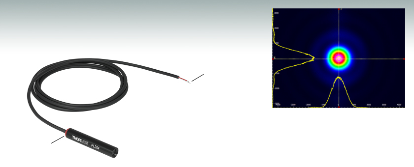
635 nm Center Wavelength, 0.9 mW Output Power
Bare Wire Leads
Color at End of Module Corresponds to Laser's Spectral Color
Sample beam profile of the PL204 USB laser module, measured using our BC106N-VIS CCD beam profiler at a distance of 5 m.


Please Wait

Click to Enlarge
PL203 Laser Module Held in a KAD11NT Unthreaded Kinematic Adapter and Mounted into an FMP1 Fixed Optic Mount

Click to Enlarge
Compact Laser Module Held in an AD11F SM1-Threaded Adapter and Mounted into a KM100T Threaded Kinematic Mount


Click to Enlarge
PL203 Laser Module Held in an AD11F SM1-Threaded Adapter and Mounted into a CP44F Quick-Release Cage Plate Within a 30 mm Cage System

Features
- 405 nm, 520 nm, or 635 nm Typical Center Wavelength
- 0.9 mW Typical Output Power
- Collimated Output
- Ø11 mm Compact, Electrically Isolated Housing
- Bare Wire Leads for OEM Integration
- Mounting Accessories Available
These compact laser modules feature a typical output power of 0.9 mW (laser safety Class 2) at a 405 nm, 520 nm, or 635 nm typical center wavelength. The collimated output has a Ø3 mm round beam profile at 50 mm from the housing. These modules offer single-spatial-mode output in compact, electrically isolated cylindrical housings and are ideal for use as alignment lasers in optical systems. As these diodes are not thermally stabilized, their optical output power may fluctuate slightly during operation.
The modules have unterminated wire leads for integration into OEM or industrial applications. The red wire is the 5 VDC input wire. We recommend powering these lasers with a user-supplied 5 VDC power supply, which must be connected to the wire leads by the user. For compact laser modules with connectors, see our USB-equipped laser modules and phono-jack-equipped laser modules.
Mounting Options
The Ø11 mm housing is compatible with our line of optomechanical components through the use of various mounting adapters, as shown in the images to the right. Depending on the adapter chosen, these laser modules can be directly mounted into either internally SM1-threaded (1.035"-40) components or mechanics with a Ø1" bore. Further details on each adapter and its compatibility with our line of optomechanics can be found below.
Thorlabs also offers a Mini-Series kinematic mount for Ø11 mm laser diode modules (available below). This kinematic mount is among our smallest kinematic mounts available and features 4-40 (M3) taps for mounting onto our Ø6 mm Mini-Series Posts.
Laser Safety and Classification
Safe practices and proper usage of safety equipment should be taken into consideration when operating lasers. The eye is susceptible to injury, even from very low levels of laser light. Thorlabs offers a range of laser safety accessories that can be used to reduce the risk of accidents or injuries. Laser emission in the visible and near infrared spectral ranges has the greatest potential for retinal injury, as the cornea and lens are transparent to those wavelengths, and the lens can focus the laser energy onto the retina.
 |
 |
 |
 |
 |
 |
 |
 |
 |
Safe Practices and Light Safety Accessories
- Thorlabs recommends the use of safety eyewear whenever working with laser beams with non-negligible powers (i.e., > Class 1) since metallic tools such as screwdrivers can accidentally redirect a beam.
- Laser goggles designed for specific wavelengths should be clearly available near laser setups to protect the wearer from unintentional laser reflections.
- Goggles are marked with the wavelength range over which protection is afforded and the minimum optical density within that range.
- Laser Safety Curtains and Laser Safety Fabric shield other parts of the lab from high energy lasers.
- Blackout Materials can prevent direct or reflected light from leaving the experimental setup area.
- Thorlabs' Enclosure Systems can be used to contain optical setups to isolate or minimize laser hazards.
- A fiber-pigtailed laser should always be turned off before connecting it to or disconnecting it from another fiber, especially when the laser is at power levels above 10 mW.
- All beams should be terminated at the edge of the table, and laboratory doors should be closed whenever a laser is in use.
- Do not place laser beams at eye level.
- Carry out experiments on an optical table such that all laser beams travel horizontally.
- Remove unnecessary reflective items such as reflective jewelry (e.g., rings, watches, etc.) while working near the beam path.
- Be aware that lenses and other optical devices may reflect a portion of the incident beam from the front or rear surface.
- Operate a laser at the minimum power necessary for any operation.
- If possible, reduce the output power of a laser during alignment procedures.
- Use beam shutters and filters to reduce the beam power.
- Post appropriate warning signs or labels near laser setups or rooms.
- Use a laser sign with a lightbox if operating Class 3R or 4 lasers (i.e., lasers requiring the use of a safety interlock).
- Do not use Laser Viewing Cards in place of a proper Beam Trap.
Laser Classification
Lasers are categorized into different classes according to their ability to cause eye and other damage. The International Electrotechnical Commission (IEC) is a global organization that prepares and publishes international standards for all electrical, electronic, and related technologies. The IEC document 60825-1 outlines the safety of laser products. A description of each class of laser is given below:
| Class | Description | Warning Label |
|---|---|---|
| 1 | This class of laser is safe under all conditions of normal use, including use with optical instruments for intrabeam viewing. Lasers in this class do not emit radiation at levels that may cause injury during normal operation, and therefore the maximum permissible exposure (MPE) cannot be exceeded. Class 1 lasers can also include enclosed, high-power lasers where exposure to the radiation is not possible without opening or shutting down the laser. |  |
| 1M | Class 1M lasers are safe except when used in conjunction with optical components such as telescopes and microscopes. Lasers belonging to this class emit large-diameter or divergent beams, and the MPE cannot normally be exceeded unless focusing or imaging optics are used to narrow the beam. However, if the beam is refocused, the hazard may be increased and the class may be changed accordingly. |  |
| 2 | Class 2 lasers, which are limited to 1 mW of visible continuous-wave radiation, are safe because the blink reflex will limit the exposure in the eye to 0.25 seconds. This category only applies to visible radiation (400 - 700 nm). |  |
| 2M | Because of the blink reflex, this class of laser is classified as safe as long as the beam is not viewed through optical instruments. This laser class also applies to larger-diameter or diverging laser beams. |  |
| 3R | Lasers in this class are considered safe as long as they are handled with restricted beam viewing. The MPE can be exceeded with this class of laser, however, this presents a low risk level to injury. Visible, continuous-wave lasers are limited to 5 mW of output power in this class. |  |
| 3B | Class 3B lasers are hazardous to the eye if exposed directly. However, diffuse reflections are not harmful. Safe handling of devices in this class includes wearing protective eyewear where direct viewing of the laser beam may occur. In addition, laser safety signs lightboxes should be used with lasers that require a safety interlock so that the laser cannot be used without the safety light turning on. Class-3B lasers must be equipped with a key switch and a safety interlock. |  |
| 4 | This class of laser may cause damage to the skin, and also to the eye, even from the viewing of diffuse reflections. These hazards may also apply to indirect or non-specular reflections of the beam, even from apparently matte surfaces. Great care must be taken when handling these lasers. They also represent a fire risk, because they may ignite combustible material. Class 4 lasers must be equipped with a key switch and a safety interlock. |  |
| All class 2 lasers (and higher) must display, in addition to the corresponding sign above, this triangular warning sign |  |
|
| Posted Comments: | |
katukuni minagawa
(posted 2020-12-18 15:37:30.503) Hello
What is the material of the lens of PL204? soswald
(posted 2020-12-18 03:45:43.0) Dear Katukuni,
thank you for your feedback. The lens is an achromatic doublet made from BK7 and SF12 glass. Jim Trice
(posted 2020-02-14 12:24:36.923) What is the wire gage on the flying leads for the PL203 laser diode module? MKiess
(posted 2020-02-17 10:18:00.0) This is a response from Michael at Thorlabs. Thank you for your inquiry!
This laser has a two-phase, highflex control cable with a cable diameter of 0.5mm. Yongjin Lee
(posted 2019-12-26 01:05:06.53) Hi, I'm Yongjin.
I have som question for pl204.
what is VCC wire color? mdiekmann
(posted 2019-12-30 03:45:13.0) This is a response from Meike at Thorlabs: Thank you for your feedback! The red wire is the + 5 VDC input. Please feel free to contact your local tech support team if you have further questions about this! |
| Click Image for Full View |  |
 |
 |
| Item # | PL206 | PL203 | PL204 |
| Wavelength (Typical) | 405 nm | 520 nm | 635 nm |
| Output Power (Typical) | 0.9 mW | ||
| Laser Safety Class | Class 2 | ||
| Beam Shapea |
Round, Ø3 mm (Typical) at 5 cm | ||
| Typical Beam Profiles (Click Icon for Details) |
 |
 |
 |
| Housing Dimensions | Ø11.0 mm x 60.2 mm | ||
| Complete Specificationsb | |||
| Alternative USB-Equipped Item # | PL205 | PL201 | PL202 |
These adapters mount the laser diode housing into SM1 (1.035"-40) lens tubes, 30 mm cage systems, Ø1/2" posts, or Ø1/2" or Ø1" mounts. Please see the application photos in the Overview tab for examples.
The KAD11F and KAD11NT adapters provide ±6° of pitch and yaw adjustment. Two 80 TPI fine adjustment screws on the front plate of the adapter control the pitch and yaw position and can be turned using a 5/64" (2.0 mm) hex key.
| Click Image to Enlarge |  |
 |
 |
 |
 |
| Item # | AD11BA | AD11F | AD11NT | KAD11F | KAD11NT |
| Description | Unthreaded Adapter with a 1/2" Outer Diameter | Externally SM1-Threaded Adapter |
Unthreaded Adapter with a 1" Outer Diameter | Externally SM1-Threaded Kinematic Adapter with Pitch and Yaw Adjustment |
Unthreaded Kinematic Adapter with a 1" Outer Diameter and Pitch and Yaw Adjustment |
| Diode Module Housing Diameter | 11 mm | ||||

 Zoom
Zoom
Click to Enlarge
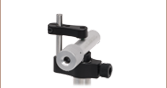
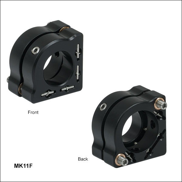
PL201 USB Laser Module Mounted in a MK11F Mini-Series Kinematic Mount
- Securely Mount Ø11 mm Laser Diode Modules
- Angular Range: ±4°
- Compact Nominal Footprint: 0.79" x 0.52" (20.0 mm x 13.3 mm)
- Resolution: 13 mrad (0.77°) per Revolution via Two M2.5 x 0.20 Precision Adjusters
- 4-40 (M3) Mounting Holes Allow for Left- or Right-Handed Orientation
Thorlabs' Mini-Series Kinematic Mount for Cylindrical Components is our most compact solution for mounting the Ø11 mm laser diode modules sold above. This two-adjuster kinematic mount features a nominal 0.79" x 0.52" (20.0 mm x 13.2 mm) footprint, which is the same as our Mini-Series kinematic mirror mounts. Cylindrical components are secured at three points using a nylon-tipped locking screw and a double-bored mounting hole. Both the nylon-tipped setscrew and the two M2.5 x 0.20 adjuster screws accept a 0.050" (1.3 mm) hex key (not included).
For ease of adjustment, we recommend using the 0.050" hex key thumbscrews. We also offer a locking collar and spanner wrench for locking the adjuster screws in a desired position or for creating a hard stop.