 Products Home / Optomechanical Components / Optical Post Assemblies / Ø1.5" Post Assemblies / Ø1.5" Post Basics
Ø1.5" Post Basics
- Solid Stainless Steel Construction
- Stackable Design Provides Flexibility for Rigid Structures
- Wide Range of Accessories Available
- Solid Stainless Steel Construction
- Stackable Design Provides Flexibility for Rigid Structures
- Wide Range of Accessories Available
1/4"-20 Tapped Holes On Both Ends
(M6 Taps on Metric Versions)
1/4"-20 Tapped Holes On Both Ends
(M6 Taps on Metric Versions)
Ø1.5" Post Spacers
Ø1.5" Post Spacers
1/4" (M6) Counterbores
(4 Top, 1 Bottom)
1/4" (M6) Counterbores
(4 Top, 1 Bottom)
1/4" (M6) Counterbored Slots
1/4"-20 Center Tap (M6 Tap in PB2/M)
1/4" (M6) Counterbored Slots
1/4"-20 Center Tap (M6 Tap in PB2/M)
PB4
PB4
PB1
PB1
PB2
PB2
PS10M
PS10M
PS7M
PS7M
PS4M
PS4M
PS1M
P14
PS1M
P12
P14
P10
P12
P8
P10
P6
P8
P6
P5
P5
P4
P4
P3
P3
P2
P2
P1.5
P1.5
P1
P1
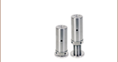
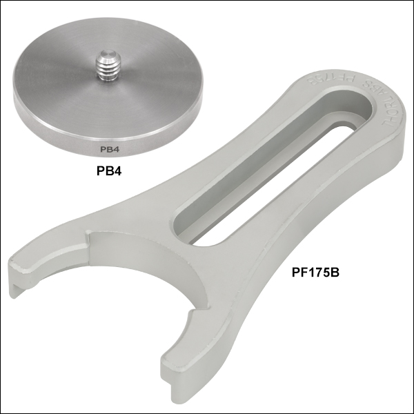
PF175B Clamping Fork Securing a Ø1.5" Post with a PB4 Base Adapter
PF175B Clamping Fork Securing a Ø1.5" Post with a PB4 Base Adapter


Please Wait
Our Ø1.5" Mounting Posts, which are fabricated from nonmagnetic 303 stainless steel, offer a wide range of basic building blocks for assembling large, rigid, 3D structures. The post products detailed on this page are the most essential construction elements onto which a host of accessories can be fastened. The solid stainless steel construction of our posts, post spacers, and post bases are complimented by large-diameter relief cuts at end interface points to provide exceptional strength and rigidity.
The stackable P-Series Posts and Post Spacers can be combined to offer a wide range of achievable mounting heights, while the P-Series Bases offer versatility when fastening posts to an optical table. A 1/4"-20 (M6) tapped hole in each post end provides sufficient clamping strength to join to posts, effectively making them one longer rigid post.
| Posted Comments: | |
joseph.gallagher
(posted 2016-09-28 08:18:23.207) The solidworks files for all the metric posts will not load, file error. I do not have this problem with any other product I tried from the site jlow
(posted 2016-09-28 11:19:54.0) Response from Jeremy at Thorlabs: The SolidWorks files were created using SolidWorks 2016 and it will not open on older version of SolidWorks. To get around that, you can download and use the STEP files instead. Thorlabs
(posted 2010-12-07 10:00:31.0) Response from Javier at Thorlabs to Vorvick: Thank you for following up with us. We will develop a solution in order to prevent deflection of the fork under the load of the screw. Please contact us at techsupport@thorlabs.com with your contact information so that we can keep you updated. user
(posted 2010-12-06 20:39:19.0) A response to Adam for Vorvick. Your are correct that the fork is bowing, but this really has nothing to do with the 3-point contact as you mentioned, rather it is caused by simple deflection of the fork under the load of the screw. In this case the fork bowed so much that the mid portion made contact with the mounting surface (optical table) and thus made it not usable. I suspect that this fork is made of aluminum and that combined with small clearance will casue this problem. apalmentieri
(posted 2010-02-02 20:07:28.0) A response from Adam at Thorlabs to Vorvick: I would like to get more information about the clamping fork is being used. From the description, it almost sounds like you are experiencing a bowing issue which should not happen due to the three point contact that the design permits. I will email you directly to get more information. vorvick_c
(posted 2010-02-02 00:25:33.0) fork is too flexible - touches table where the screw is - defeats the purpose - having to redo my setup without it. siddiqi
(posted 2009-08-22 17:05:06.0) For all post types -- it would be extremely useful if the posts were marked (e.g. laser etching) with length, diameter, and tapped hole size/pitch on the side (and ends if possible). Spacers could be marked on their faces.
A 2 inch post looks an awful lot like a 50 mm post, and a 1/4-20 tap looks a lot like an M6. Labels would ensure that the correct part is pulled out of the drawer the first time... |

 Zoom
Zoom
Click to Enlarge
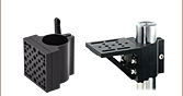
Our Ø1.5" posts can also be used to mount our Post-Mounted ScienceDesk™ shelves, brackets, and monitor mount.

Click to Enlarge
Top of Metric Ø1.5" Post.

Click to Enlarge
Top of Imperial Ø1.5" Post.
- Solid Nonmagnetic Stainless Steel Construction
- Ideal for Large, Rigid, 3D Structures
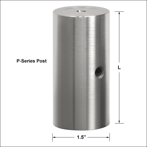
These solid stainless steel Ø1.5" (Ø38 mm) P-series posts, offered in heights ranging from 1" (25 mm) to 14" (350 mm), are designed for constructing extremely rigid assemblies with demanding structural integrity requirements. The stackable design, which has 1/4"-20 (M6) tapped holes on both ends, allows the joining of multiple mounting posts to achieve an array of lengths. These posts have a thread depth between 0.375" (9.525 mm) and 0.400" (10.16 mm). Using a 3/16" (5 mm) balldriver inserted through the side clearance hole, sufficient torque can be achieved to securely tighten stacked posts. These posts also feature a large-diameter relief cut on both ends for mounting stability.
For ease in distinguishing between the imperial and metric versions, the tops and bottoms of the metric posts have a ring engraved on them, while the imperial posts have no such engraving (see images above on the right).
Post spacers are also available below to provide greater flexibility in height. Please note that if your application requires tighter tolerances than those offered by the P-series [±0.005" (±0.127 mm)] or height adjustability, we recommend using the BLP01 Adjustable Height Post.

 Zoom
Zoom- Solid Nonmagnetic Stainless Steel Construction
- Ideal for Achieving "In-Between" Post Lengths
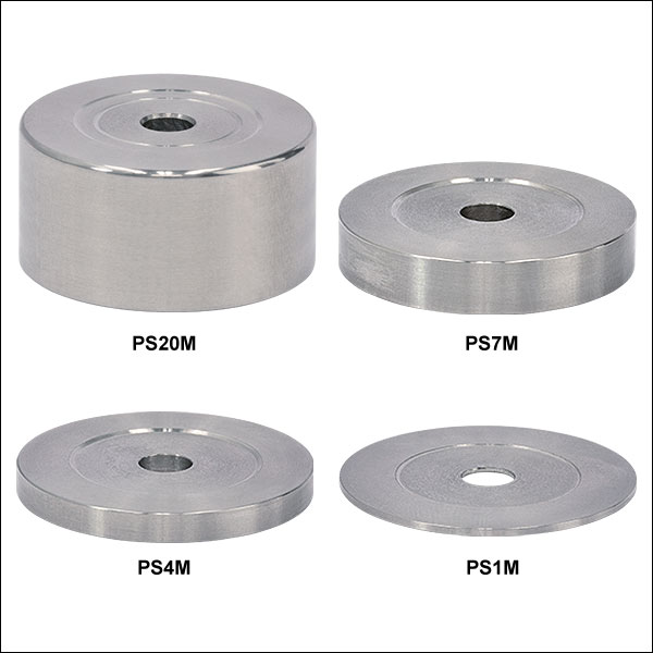
These solid stainless steel Ø1.5" (Ø38 mm) post spacers are designed to achieve post heights that are between those offered by any two P-Series posts. For example, a post height of 28 mm is achieved simply by attaching a PS3M (3 mm post spacer) to a P25/M (25 mm post). The spacer provides a center-located 1/4" (M6) clearance hole for access to the P-series posts as well as a large-diameter relief cut on both spacer ends for mounting stability. Please note that for applications requiring tight height tolerances, we recommend using a BLP01 Adjustable Height Post.

 Zoom
Zoom

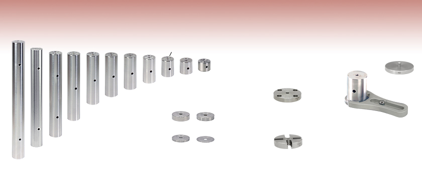
- PB4(/M) Adapter Converts Ø1.5" Posts to Pedestal-Style Mounts
- Clamping Fork Secures Pedestal-Style Mount to a Breadboard or Optical Table
- 2.12" (53.8 mm) Long Counterbored Slot
- Swivel Fork 360° to Select Most Convenient Mounting Hole
- Available Individually or in Packs of 5
Pedestal Base Adapter
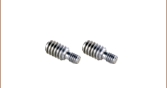
The PB4(/M) pedestal base adapter features a 1/4"-20 (M6)-threaded stud, which fits into the bottom of our Ø1.5" posts to convert them into pedestal-style mounts. Made from solid 303 stainless steel with a 1.85" (47.0 mm) outer diameter, this adapter allows these posts to be used with our PF175B clamping fork.
Clamping Fork
The PF175B clamping fork is designed to provide exceptional clamping force when used with our Ø1.5" posts that have been adapted using the PB4(/M) pedestal bases. This clamping fork can also be used with our Ø1" post holders or BLP01 adjustable-height post without any need for the PB4(/M) bases.
Made from stainless steel, the PF175B clamping fork creates three points of contact with the table for high stability. The 2.12" (53.8 mm) long counterbored slot for 1/4"-20 (M6) cap screws allows the most convenient mounting hole to be selected and creates flexibility in the positioning of post assemblies. Please note that significant overtightening of clamping forks can deform the surface of an optical table, which can cause misalignment of components and decrease stability.
The PF175B clamping fork is available idividually or in packs of five.

 Zoom
ZoomPB1
This universal post base has a 1/4" (M6) counterbored hole in the center that allows the base to be attached to a Ø1.5" mounting post using a 1/4"-20 (M6) cap screw. Four 1/4" (M6) counterbored holes are provided at the proper spacing for compatibility with an imperial or metric optical table or optical breadboard that contains mounting holes on 1" or 25 mm centers.
PB2 and PB2/M
These post bases have counterbored slots that allow for additional freedom in the placement of Ø1.5" mounting posts. The PB2 has a center-tapped 1/4"-20 hole while the PB2/M has a center-tapped M6 hole. The PB2/M has an identifying ring engraved around the tapped hole on the bottom face of the base. Use a 1/4"-20 (M6) setscrew to attach the PB2 (PB2/M) base to a Ø1.5" mounting post.
Pedestal Base Adapter
The PB4(/M) pedestal base adapter features a 1/4"-20 (M6)-threaded stud, which fits into the bottom of our Ø1.5" posts to convert them into pedestal-style mounts. The adapter is made from solid 303 stainless steel with a 1.85" (47.0 mm) outer diameter. It can be secured to a breadboard using the CL8 clamp (sold separately below).

 Zoom
Zoom
Click to Enlarge
CL8 Clamps Securing P4 Ø1.5" Post on PB4 Pedestal

Click to Enlarge
CL8 Cross-Sectional View
- Compatible with Ø1" and Ø1.5" Posts
- Two-Point Contact with Pedestal Post Perimeter
- Line Contact on Table for More Secure Clamping Force
Thorlabs' CL8 pedestal post clamp secures our Ø1" and Ø1.5" pedestal posts to an optical table or breadboard. Its V-shaped tip provides two-point contact with the post perimeter and its rounded edge increases the contact area along the table.

 Zoom
Zoom- Mark the Position of Ø1" and Ø1.5" Posts within an Optical System
- Realignment Based on Two Contact Points
- Third Contact Point for Realigning Square Components
- Swivel Head Retainer Available with 200° of Rotation
Thorlabs' Position Retainers can be used to realign posts that have been removed from an optical system. They act as markers on the breadboard or optical table in the event that you need to remove a post from your setup. The two dots near the ends of the outer arms of the retainer mark the two points of post contact. The third dot, located within the V-groove, is for retaining the position of a square base or other squared-off component. For more information on using our retainers with square components, click here.
The RSPC Fixed Retainer is a compact solution for use with Ø1" and Ø1.5" Pedestal Posts. The post should be independently clamped down before aligning the RSPC retainer. After the retainer is mounted in place, the post can be removed from the setup and then later placed back into the same position.
The RSPCS(/M) Swivel Retainer features a swivel head for 200° of rotational adjustment. This allows for access to additional mounting holes on the breadboard. The post should be independently locked before aligning RSPCS(/M) retainer. Partially loosen the tension adjuster screw and then mount the retainer to a breadboard tap while maintaining contact with the post. Lastly, tighten the tension adjuster screw. After this the component can be removed from the setup and then later placed back into the same position.


Click to Enlarge RSPCS Swiveling Position Retainer