 Products Home
High-Speed Fiber-Coupled Detectors

- Sensitive to Wavelengths from 400 - 1700 nm
- Bandwidths from 1 to 5 GHz
- Rise Times as Short as 50 ps
DET08CFC
DET02AFC
DET01CFC
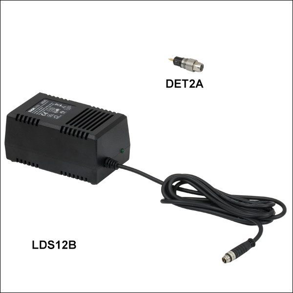
DET2B
Replaces the battery in our DET series detectors and includes the LDS12B power supply and DET2A power adapter, shown connected.


Please Wait
| Selection Guide for Fiber-Coupled Detectors | |||
|---|---|---|---|
| Wavelength | Element | Bandwidth | Model |
| 400 - 1100 nm | Si | 1 GHz | DET02AFC |
| 2 GHz | DET025AFC | ||
| 800 - 1700 nm | InGaAs | 1.2 GHz | DET01CFC |
| 800 - 1700 nm | 5 GHz | DET08CFC | |


Click to Enlarge
PDA200C Benchtop Photodiode Amplifier Connected to a DET02AFC Photodetector Using an SMA-to-BNC Cable
Features
- Four Models Cover Wavelengths from 400 - 1700 nm
- Bandwidths Ranging from 1 to 5 GHz
- Rise Times from 50 ps to 1 ns
- Connect to Single Mode (SM) or Multimode (MM) Fiber
- FC/PC Fiber Input Connector
- SMA Output Connector
Thorlabs offers a variety of fiber-coupled, high-speed, high-bandwidth photodetectors designed to connect to a single mode or multimode fiber with an FC/PC-terminated input. Together, these detectors are sensitive from the visible to the near infrared (400 - 1700 nm); please see the "Selection Guide" table to the right for the exact spectral range covered by each detector. All detectors shown here feature GHz signal bandwidths and the same ease of use as the rest of our popular DET series. These detectors are designed to perform in test or measurement applications, including research in the fields of data communications, analog microwave, and general high-speed photonics. For comparable detection of free-space radiation, Thorlabs offers high-speed free-space detectors. We also carry a variety of internally biased photodiodes that feature the same ease of use as our fiber-coupled photodetectors but operate at slower speeds. Our biased photodetectors are compatible with our benchtop photodiode amplifier and PMT transimpedance amplifier.
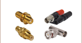
These fiber-coupled detectors are reverse biased and contain an internal bias battery, producing a linear response to the incident input light. To maintain the high signal bandwidth, the signal is output through an SMA connector. Thorlabs offers a complete range of electrical adapters and cables, including SMA cables and SMA-to-BNC adapters, for monitoring the output signal with an oscilloscope or other measurement electronics.
Our Si-based fiber-coupled detectors are designed for use in the 400 - 1100 nm wavelength range and provide a bandwidth of 1 GHz (Item # DET02AFC) or 2 GHz (Item # DET025AFC). For applications extending into the near infrared, consider our InGaAs-based fiber-coupled detectors, which provide detection in the 800 - 1700 nm wavelength range and provide a bandwidth of 1.2 GHz (Item # DET01CFC) or 5 GHz (Item # DET08CFC). When looking at high-speed signals, Thorlabs recommends using a 50 Ω load resistor. For lower bandwidth applications, our variable terminator or fixed stub-style terminators quickly adjusts the measured voltage.
All of these detectors include a replaceable A23 12 VDC Bias battery, providing an extremely low-noise power source. This battery can be replaced by the DET2B power adapter bundle (sold below), which is ideal for applications where a small increase in the signal noise due to noise in the line voltage is permissible or the finite lifetime of a battery is not acceptable. Please note that due to slight physical variations of the positive terminal from manufacturer to manufacturer, Thorlabs recommends using only an Energizer® battery in our DET series photodetectors.
| Item # | DET02AFC | DET025AFC | DET01CFC | DET08CFC |
|---|---|---|---|---|
| Wavelength Range | 400 - 1100 nm | 400 - 1100 nm | 800 - 1700 nm | 800 - 1700 nm |
| Material | Si | Si | InGaAs | InGaAs |
| Bandwidth (-3 dB)a,b,f | 1 GHz | 2 GHz | 1.2 GHz | 5 GHz |
| Fiber Input | FC/PC | FC/PC | FC/PCc | FC/PCc |
| Signal Output | SMA | SMA | SMA | SMA |
| Minimum Resistor Load | 50 Ω | 50 Ω | 50 Ω | 50 Ω |
| Maximum Peak Power | 18 mW | 18 mW | 18 mW | 100 mW |
| Saturation Power (CW) | - | - | 5.5 mW (1550 nm)b | - |
| Output Voltage | 0 to 3.3 V (50 Ω) 0 to 10 V (Hi-Z) |
2 V (Max)d | 0 to 3.5 V (50 Ω)e 0 to 10 V (Hi-Z) |
2 V (Max)d |
| Rise Time (tr) | 1 ns @ 730 nma,b,f (Max) | 150 ps @ 653 nm, 20/80%a,b,f (Typ.) | <1 nsa,b,f,g @ 1310 nm | 70 psa,b,f @ 952 nm, 20/80% (Typ.) |
| Fall Time (tf) | 1 ns @ 730 nma,b,f (Max) | 150 ps @ 653 nm, 80/20%a,b,f (Typ.) | <1 nsa,b,f,g @ 1310 nm | 110 psa,b,f @ 952 nm, 80/20% (Typ.) |
| Bias Voltage | 12 V | |||
| Dark Current | 126 pAh | 35 pAa,h | 0.235 nAa,h | 1.5 nAa,h |
| NEP (Maximum) | 9.5 x 10⁻¹⁵ W/√Hz (@ 730 nm) |
9.29 x 10⁻¹⁵ W/√Hz (@ 730 nm) |
4.5 x 10⁻¹⁵ W/√Hz (@ 1550 nm) |
2 x 10-15 W/√Hz (@ 1550 nm) |
| Junction Capacitance | 1.73 pF (Max) | 1.73 pF (Max) | 2.4 pF (Typical) | 0.3 pF |
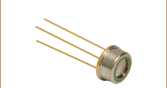
| Photodiode Element | FDS02 | FDS02 | FGA01FC | - |


Signal Output
SMA Female

0 - 10 V w/ 50 Ω
Battery Lifetime
When using a battery-operated photodetector it is important to understand the battery’s lifetime and how this affects the operation of the detector. As a current output device, the output current of the photodetector is directly proportional to the light incident on the detector. Most users will convert this current to a voltage by using a load-terminating resistor. The resistance value is approximately equal to the circuit gain. For very high speed detectors, such as those sold on this page, it is very important to use a 50 Ω terminating resistor to match the impedance of standard coax cables to reduce cable reflections and improve overall signal performance and integrity. Most high bandwidth scopes come equipped with this termination.
The battery usage lifetime directly correlates to the current used by the detector. Most battery manufacturers provide a battery lifetime in terms of mA hr. For example, the battery supplied with the DET08CFC detectors is rated for 40 mA hrs. This means that it will reliably operate for 40 hr at a current draw of 1.0 mA. This battery will be used in the following example on how to determine battery lifetime based on usage.
For this example we have a 780 nm light source with an average 1 mW power is applied to an DET08CFC. The responsivity of a biased photodetector based on the response curve at this wavelength is 0.5 A/W. The photocurrent can be calculated as:

Given the battery has a rated lifetime of 40 mA hr, the battery will last:

or 3.3 days of continuous use. By reducing the average incident power of the light to 10 µW, the same battery would last for about 333 days when used continuously. When using the recommended 50 Ω terminating load, the 0.5 mA photocurrent will be converted into a voltage of:

If the incident power level is reduced to 10 µW, the output voltage becomes 0.25 mV. For some measurement devices this signal level may be too low and a compromise between battery life and measurement accuracy will need to be made.
When using a battery-powered, biased photodetector, it is desirable to use as low a light intensity as is possible, keeping in mind the minimum voltage levels required. It is also important to remember that a battery will not immediately cease producing a current as it nears the end of its lifetime. Instead, the voltage of the battery will drop, and the electric potential being applied to the photodiode will decrease. This in turn will increase the response time of the detector and lower its bandwidth. As a result, it is important to make sure the battery has sufficient voltage (as given in the Troubleshooting chapter of the detector's manual) for the detector to operate within its specified parameters. The voltage can be checked with a multimeter.
Another suggestion to increase the battery lifetime is to remove, or power down the light source illuminating the sensor. Without the light source, the photodetector will continue to draw current proportional to the photodetector’s dark current, but this current will be significantly smaller. For example, the DET08CFC has a dark current less than 1.5 nA.
For applications where a DET series photodetector is being continuously illuminated with a relatively high-power light source or if having to change the battery is not acceptable, we offer the DET2B power adapter bundle, which includes the power adapter and power supply (sold below). The drawback to this option is the noise in the line voltage will add to the noise in the output signal and could cause more measurement uncertainty.
Photodiode Tutorial
Theory of Operation
A junction photodiode is an intrinsic device that behaves similarly to an ordinary signal diode, but it generates a photocurrent when light is absorbed in the depleted region of the junction semiconductor. A photodiode is a fast, highly linear device that exhibits high quantum efficiency based upon the application and may be used in a variety of different applications.
It is necessary to be able to correctly determine the level of the output current to expect and the responsivity based upon the incident light. Depicted in Figure 1 is a junction photodiode model with basic discrete components to help visualize the main characteristics and gain a better understanding of the operation of Thorlabs' photodiodes.


Figure 1: Photodiode Model
Photodiode Terminology
Responsivity
The responsivity of a photodiode can be defined as a ratio of generated photocurrent (IPD) to the incident light power (P) at a given wavelength:

Modes of Operation (Photoconductive vs. Photovoltaic)
A photodiode can be operated in one of two modes: photoconductive (reverse bias) or photovoltaic (zero-bias). Mode selection depends upon the application's speed requirements and the amount of tolerable dark current (leakage current).
Photoconductive
In photoconductive mode, an external reverse bias is applied, which is the basis for our DET series detectors. The current measured through the circuit indicates illumination of the device; the measured output current is linearly proportional to the input optical power. Applying a reverse bias increases the width of the depletion junction producing an increased responsivity with a decrease in junction capacitance and produces a very linear response. Operating under these conditions does tend to produce a larger dark current, but this can be limited based upon the photodiode material. (Note: Our DET detectors are reverse biased and cannot be operated under a forward bias.)
Photovoltaic
In photovoltaic mode the photodiode is zero biased. The flow of current out of the device is restricted and a voltage builds up. This mode of operation exploits the photovoltaic effect, which is the basis for solar cells. The amount of dark current is kept at a minimum when operating in photovoltaic mode.
Dark Current
Dark current is leakage current that flows when a bias voltage is applied to a photodiode. When operating in a photoconductive mode, there tends to be a higher dark current that varies directly with temperature. Dark current approximately doubles for every 10 °C increase in temperature, and shunt resistance tends to double for every 6 °C rise. Of course, applying a higher bias will decrease the junction capacitance but will increase the amount of dark current present.
The dark current present is also affected by the photodiode material and the size of the active area. Silicon devices generally produce low dark current compared to germanium devices which have high dark currents. The table below lists several photodiode materials and their relative dark currents, speeds, sensitivity, and costs.
| Material | Dark Current | Speed | Spectral Range | Cost |
|---|---|---|---|---|
| Silicon (Si) | Low | High Speed | Visible to NIR | Low |
| Germanium (Ge) | High | Low Speed | NIR | Low |
| Gallium Phosphide (GaP) | Low | High Speed | UV to Visible | Moderate |
| Indium Gallium Arsenide (InGaAs) | Low | High Speed | NIR | Moderate |
| Indium Arsenide Antimonide (InAsSb) | High | Low Speed | NIR to MIR | High |
| Extended Range Indium Gallium Arsenide (InGaAs) | High | High Speed | NIR | High |
| Mercury Cadmium Telluride (MCT, HgCdTe) | High | Low Speed | NIR to MIR | High |
Junction Capacitance
Junction capacitance (Cj) is an important property of a photodiode as this can have a profound impact on the photodiode's bandwidth and response. It should be noted that larger diode areas encompass a greater junction volume with increased charge capacity. In a reverse bias application, the depletion width of the junction is increased, thus effectively reducing the junction capacitance and increasing the response speed.
Bandwidth and Response
A load resistor will react with the photodetector junction capacitance to limit the bandwidth. For best frequency response, a 50 Ω terminator should be used in conjunction with a 50 Ω coaxial cable. The bandwidth (fBW) and the rise time response (tr) can be approximated using the junction capacitance (Cj) and the load resistance (RLOAD):

Noise Equivalent Power
The noise equivalent power (NEP) is the generated RMS signal voltage generated when the signal to noise ratio is equal to one. This is useful, as the NEP determines the ability of the detector to detect low level light. In general, the NEP increases with the active area of the detector and is given by the following equation:

Here, S/N is the Signal to Noise Ratio, Δf is the Noise Bandwidth, and Incident Energy has units of W/cm2. For more information on NEP, please see Thorlabs' Noise Equivalent Power White Paper.
Terminating Resistance
A load resistance is used to convert the generated photocurrent into a voltage (VOUT) for viewing on an oscilloscope:

Depending on the type of the photodiode, load resistance can affect the response speed. For maximum bandwidth, we recommend using a 50 Ω coaxial cable with a 50 Ω terminating resistor at the opposite end of the cable. This will minimize ringing by matching the cable with its characteristic impedance. If bandwidth is not important, you may increase the amount of voltage for a given light level by increasing RLOAD. In an unmatched termination, the length of the coaxial cable can have a profound impact on the response, so it is recommended to keep the cable as short as possible.
Shunt Resistance
Shunt resistance represents the resistance of the zero-biased photodiode junction. An ideal photodiode will have an infinite shunt resistance, but actual values may range from the order of ten Ω to thousands of MΩ and is dependent on the photodiode material. For example, and InGaAs detector has a shunt resistance on the order of 10 MΩ while a Ge detector is in the kΩ range. This can significantly impact the noise current on the photodiode. For most applications, however, the high resistance produces little effect and can be ignored.
Series Resistance
Series resistance is the resistance of the semiconductor material, and this low resistance can generally be ignored. The series resistance arises from the contacts and the wire bonds of the photodiode and is used to mainly determine the linearity of the photodiode under zero bias conditions.
Common Operating Circuits

Figure 2: Reverse-Biased Circuit (DET Series Detectors)
The DET series detectors are modeled with the circuit depicted above. The detector is reverse biased to produce a linear response to the applied input light. The amount of photocurrent generated is based upon the incident light and wavelength and can be viewed on an oscilloscope by attaching a load resistance on the output. The function of the RC filter is to filter any high-frequency noise from the input supply that may contribute to a noisy output.

Figure 3: Amplified Detector Circuit
One can also use a photodetector with an amplifier for the purpose of achieving high gain. The user can choose whether to operate in Photovoltaic of Photoconductive modes. There are a few benefits of choosing this active circuit:
- Photovoltaic mode: The circuit is held at zero volts across the photodiode, since point A is held at the same potential as point B by the operational amplifier. This eliminates the possibility of dark current.
- Photoconductive mode: The photodiode is reversed biased, thus improving the bandwidth while lowering the junction capacitance. The gain of the detector is dependent on the feedback element (Rf). The bandwidth of the detector can be calculated using the following:

where GBP is the amplifier gain bandwidth product and CD is the sum of the junction capacitance and amplifier capacitance.
Effects of Chopping Frequency
The photoconductor signal will remain constant up to the time constant response limit. Many detectors, including PbS, PbSe, HgCdTe (MCT), and InAsSb, have a typical 1/f noise spectrum (i.e., the noise decreases as chopping frequency increases), which has a profound impact on the time constant at lower frequencies.
The detector will exhibit lower responsivity at lower chopping frequencies. Frequency response and detectivity are maximized for
![]()
| Posted Comments: | |
Nordine Hendaoui
(posted 2020-12-29 08:37:35.187) Hello,
for using the DET01CFC, We have to purchase only the DET2B as power supply. This last is powerd by 220 v?
Thanks asundararaj
(posted 2020-12-29 04:52:40.0) Thank you for contacting Thorlabs. The DET2B includes the DET power adapter and the LDS12B power supply. The power supply has a switchable AC input voltage (100, 120, or 230 VAC), which will have to be switched to 230 VAC setting. A region-specific power cord is also shipped with the LDS12B power supply based on your location. liangze pan
(posted 2020-05-18 13:10:42.937) Hey,would you mind provide the frequency response curve of the photo detector of DET025AFC/M YLohia
(posted 2020-05-27 09:39:50.0) Hello, thank you for contacting Thorlabs. Unfortunately, we do not have a frequency response curve for this detector at the moment. liangze pan
(posted 2020-05-07 15:50:29.337) Hey,would you mind to provide the frequency response curve of the photo detector of DET025AFC/M. YLohia
(posted 2020-06-09 11:16:31.0) Hello, thank you for contacting Thorlabs. I have reached out to you directly to discuss your request. Jo Wanki
(posted 2019-11-07 04:13:27.263) I have a question. I am using DET08CFC / M. I'm wondering where to fit the laser to the DET08CFC / M INPUT part when measuring the pulse width.
Currently we inspect a laser set to a 12 nsec pulse width value. If we measure from the periphery to the center of the DET08CFC / M INPUT part, a value ranging from 10.8 nsec to 13 nsec is measured.
So we wonder. Please let me know if there is any information on whether the laser should be placed in the center of the DET08CFC / M INPUT site, whether it should be around or measured. YLohia
(posted 2019-11-07 10:32:51.0) Thank you for contacting Thorlabs. For the maximum bandwidth, the spot should be <50% of the active area (ideally in the geometrical center of the photodiode). The edges of the detector tend to have a slower response time, and overfilling the detector will give a convolution of rise times across the active area. Daniel Fernando Borrero
(posted 2019-10-25 11:24:28.08) I would like to know if this detector can be used to do correlation counting experiments, I need to connect the detectors to a TCSPC module, will they work? asundararaj
(posted 2019-10-29 03:05:31.0) Thank you for contacting Thorlabs. The DET025AFC is not sensitive enough to count photons. You can find our Single Photon Counters here: https://www.thorlabs.com/newgrouppage9.cfm?objectgroup_id=5255 Philip Skochinski
(posted 2019-10-21 14:05:44.74) What is the voltage output for a given optical input? I need to be able to calculate the electrical power (in 50 Ohms) for a specific optical input power. asundararaj
(posted 2019-10-21 04:59:14.0) Thank you for contacting Thorlabs. The output voltage from the detector can be estimated from the optical power incident using following equation:
Voltage measured (V) = Optical Input (W) * Responsivity (A/W) * Terminating Resistance (Ohms)
You can find the typical responsivity in the Graphs tab of this page or in the detector Manual. user
(posted 2019-09-05 04:10:22.24) Hello,
For the DET01CFC(/M), you have specfified a Saturation Power (CW) = 5.5 mW (1550 nm) for a 50 Ohms load
But for the DET08CFC/M, it is specified a Maximum Output Voltage VOUT=2 V (Max). Could you provide me with the optical power producing this 2V or what is the Saturation Power (CW) in mW for this detector? I aks this because I have a fast modulation (GHz) on top of CW light level.
Thanks! asundararaj
(posted 2019-09-06 04:19:13.0) Thank you for contacting Thorlabs. The saturation threshold of a detector depends on many factors such as load resistance value, beam profile and size, modulation characteristics, wavelength, bias voltage, diode temperature, etc. For more details regarding this, please see our "Lab Fact" on photodiode saturation limits here: https://www.thorlabs.com/images/TabImages/Photodetector_Lab.pdf.
We do not have an official spec on the saturation of the DET08CFC. I will reach out to you directly to discuss this further. jwchew33
(posted 2018-07-09 01:53:12.373) Greeting, I have a problem on DET08CFC/M. When I input square waveform at frequencies range from 1kHz to 1MHz into the photodetector, the output results did not show square waveform as expected. However, by using the same setup using PDA50B-EC detector (input 1kHz-400kHz), square waveform were observed. The pulse width used was 10us. I'm not sure what to do next. Any help? Thanks. YLohia
(posted 2018-07-25 08:43:15.0) Hello, thank you for contacting Thorlabs. What load impedance are you using on your oscilloscope? You should be using 50 Ohms for ideal performance. Is the battery for the DET fully charged? I will reach out to you directly to troubleshoot this further. dlee103
(posted 2018-03-16 15:55:18.063) What is the saturation threshold in mW? YLohia
(posted 2018-04-19 03:39:43.0) Hello, thank you for contacting Thorlabs. The saturation threshold of a detector depends on many factors such as load resistance value, beam profile and size, modulation characteristics, wavelength, bias voltage, diode temperature, etc. For more details regarding this, please see our "Lab Fact" on photodiode saturation limits here: https://www.thorlabs.com/images/TabImages/Photodetector_Lab.pdf. The DET025AFC is designed for pulsed/modulated light sources so the saturation limit can depend heavily on modulation characteristics. For example, a few milliwatts (1 to 2 mW for peak wavelength) is a safe theoretical estimate for CW sources, while we spec 18mW of peak power for pulsed sources. There is a resistor in series as a part of an RC circuit within the detector packaging, which limits the CW saturation power. user
(posted 2016-11-04 16:39:22.64) The manual linked for DET01CFC says that the battery should be installed negative side in. The diagram on the detector and the spring inside the battery cap suggest the opposite is true. tfrisch
(posted 2016-11-04 04:50:19.0) Hello, thank you for contacting Thorlabs. Section 4.11 of the manual calls for the battery to be inserted into the cap with the negative terminal inside the cap (in contact with the coil spring). When the cap is threaded back onto the housing, that will put the positive of the battery in the housing. mitch
(posted 2016-03-22 09:10:48.767) Hi, would it be possible for me to buy the metal fibre attachment that is attached to the input of these devices, by itself? I have purchased four of the free space, window versions (along with several tens of thousand dollars of other stuff) but I would like to try attach a fibre and I don't want to buy another set (the budget is now mostly spent!). Thanks besembeson
(posted 2016-03-24 10:23:31.0) Response from Bweh at Thorlabs USA: The sensor for the fiber versions comes coupled to the fiber connector. I will contact you if this is still suitable for your application. songtaodu
(posted 2016-01-21 17:08:49.07) When I used DET08CFC to detect output light of a fiber laser,wavelength of this laser is 1550nm and output is CW, the output voltage of DET08CFC kept at 13.2V while the laser power varied from 0.5mW to 3mW.
When I turn off the laser, the output voltage of DET08CFC is zero.
Can you tell me why this happened? Thanks! jlow
(posted 2016-01-22 01:28:18.0) Response from Jeremy at Thorlabs: It seems like you are basically measuring the voltage of the battery. The DET08CFC output s current signal. To use that with an oscilloscope or a voltmeter, you will need a load resistor or a terminator in series and measure the voltage drop across the resistor /terminator instead. An example of the terminator would be the T4119 terminator. rmillett
(posted 2014-09-03 11:28:46.62) Could a calibrated transfer curve be available for these detectors? In particular a response curve that could be calibrated out from low (kHz) frequencies to 5GHz? jlow
(posted 2014-09-04 04:06:29.0) Response from Jeremy at Thorlabs: We will look into measuring this and will e-mail you directly on our findings. kmurari
(posted 2013-05-03 16:17:01.92) My DET02AFC appears to be AC coupled although the manual says the SMA output is DC coupled. I have checked the battery, it is at >12 V. Can you please confirm if the unit is indeed DC coupled?
Thanks! jlow
(posted 2013-05-03 18:07:00.0) Response from Jeremy at Thorlabs: The DET02AFC should be DC-coupled. I will contact you directly to troubleshoot this. jlow
(posted 2012-12-21 10:39:00.0) Response from Jeremy at Thorlabs: The detector's active area has a diameter of Ø120µm. There's also a Ø1.5mm ball lens in front of the detector. The output from a SMF28 fiber should be fully captured by the detector. For MM fiber, we recommend using a fiber with at most 50µm core size (around 0.2 NA). neil.troy
(posted 2012-12-06 00:01:17.15) For the fiber coupled devices will a single mode fiber's (say SMF-28 for example) divergence be fully captured by the detector? What about a multi-mode fiber? ie. what is the distance from the output face of the fiber to the detector surface as well as what are the detector's active areas? tcohen
(posted 2012-04-05 15:19:00.0) Response from Tim at Thorlabs to jzheng: Thank you for your feedback! The typical rise time of the DET02 will still be ~50ps at your wavelength. jzheng
(posted 2012-03-26 01:56:40.0) For the wavelength 1053nm, is the rise time of the DET02 (Si) still be 50ps? or will be longer? thank you. jjurado
(posted 2011-02-08 18:27:00.0) Response from Javier at Thorlabs to last poster: Thank you very much for submitting your request. For the high bandwidth detectors, a switch is not included since it significantly impairs the BW performance of the detector. In general, the DET’s draw very little current when no light is applied to the sensor. A battery will last on the order of years without a light signal applied. For these detectors, it is recommended that the light source is removed from the sensor when not being used. This will preserve the battery life. user
(posted 2011-02-08 17:00:05.0) It looks free space DET series has a battery switch. Do I have to remove a battery out of a box of the fiber input DETs every time? klee
(posted 2009-10-05 14:39:34.0) A response from Ken at Thorlabs to dinglu81: Thank you for pointing out the discrepancy. It should be 10^-15. dinglu81
(posted 2009-10-02 05:41:25.0) the NEP of this detector is 10^-15 in the specs but 10^-14 in the catalog. Which one is correct? Greg
(posted 2009-02-18 15:37:16.0) A response from Greg at Thorlabs to remi.riviere: Thank you for your interest in Thorlabs products. Please see the e-mail I sent you and reply to it with the detector you are looking for more information on. I will then check what other information we have available on it. remi.riviere
(posted 2009-02-18 05:01:42.0) Please provide a gain curve as well as the dynamic range of this detector. acable
(posted 2008-08-31 12:59:35.0) Please add NEP data. |
The following table lists Thorlabs' selection of photodiodes and photoconductive detectors. Item numbers in the same row contain the same detector element.
| Photodetector Cross Reference | ||||||
|---|---|---|---|---|---|---|
| Wavelength | Material | Unmounted Photodiode |
Unmounted Photoconductor |
Mounted Photodiode |
Biased Detector |
Amplified Detector |
| 150 - 550 nm | GaP | - | - | SM05PD7A | DET25K2 | PDA25K2 |
| 200 - 1100 nm | Si | FDS010 | - | SM05PD2A SM05PD2B |
DET10A2 | PDA10A2 |
| Si | - | - | SM1PD2A | - | - | |
| 320 - 1000 nm | Si | - | - | - | - | PDA8A2 |
| 320 - 1100 nm | Si | FD11A | SM05PD3A | PDF10A2 | ||
| Si | - | - | - | DET100A2 | PDA100A2 | |
| 340 - 1100 nm | Si | FDS10X10 | - | - | - | - |
| 350 - 1100 nm | Si | FDS100 FDS100-CAL a |
- | SM05PD1A SM05PD1B |
DET36A2 | PDA36A2 |
| Si | FDS1010 FDS1010-CAL a |
- | SM1PD1A SM1PD1B |
- | - | |
| 400 - 1000 nm | Si | - | - | - | - | PDA015A(/M) FPD310-FS-VIS FPD310-FC-VIS FPD510-FC-VIS FPD510-FS-VIS FPD610-FC-VIS FPD610-FS-VIS |
| 400 - 1100 nm | Si | FDS015 b | - | - | - | - |
| Si | FDS025 b FDS02 c |
- | - | DET02AFC(/M) DET025AFC(/M) DET025A(/M) DET025AL(/M) |
- | |
| 400 - 1700 nm | Si & InGaAs | DSD2 | - | - | - | - |
| 500 - 1700 nm | InGaAs | - | - | - | DET10N2 | - |
| 750 - 1650 nm | InGaAs | - | - | - | - | PDA8GS |
| 800 - 1700 nm | InGaAs | FGA015 | - | - | - | PDA015C(/M) |
| InGaAs | FGA21 FGA21-CAL a |
- | SM05PD5A | DET20C2 | PDA20C2 PDA20CS2 |
|
| InGaAs | FGA01 b FGA01FC c |
- | - | DET01CFC(/M) | - | |
| InGaAs | FDGA05 b | - | - | - | PDA05CF2 | |
| InGaAs | - | - | - | DET08CFC(/M) DET08C(/M) DET08CL(/M) |
PDF10C/M | |
| 800 - 1800 nm | Ge | FDG03 FDG03-CAL a |
- | SM05PD6A | DET30B2 | PDA30B2 |
| Ge | FDG50 | - | - | DET50B2 | PDA50B2 | |
| Ge | FDG05 | - | - | - | - | |
| 900 - 1700 nm | InGaAs | FGA10 | - | SM05PD4A | DET10C2 | PDA10CS2 |
| 900 - 2600 nm | InGaAs | FD05D | - | - | DET05D2 | - |
| FD10D | - | - | DET10D2 | PDA10D2 | ||
| 950 - 1650 nm | InGaAs | - | - | - | - | FPD310-FC-NIR FPD310-FS-NIR FPD510-FC-NIR FPD510-FS-NIR FPD610-FC-NIR FPD610-FS-NIR |
| 1.0 - 5.8 µm | InAsSb | - | - | - | - | PDA10PT(-EC) |
| 2.0 - 5.4 µm | HgCdTe (MCT) | - | - | - | - | PDA10JT(-EC) |
| 2.0 - 8.0 µm | HgCdTe (MCT) | VML8T0 VML8T4 d |
- | - | - | PDAVJ8 |
| 2.0 - 10.6 µm | HgCdTe (MCT) | VML10T0 VML10T4 d |
- | - | - | PDAVJ10 |
| 2.7 - 5.0 µm | HgCdTe (MCT) | VL5T0 | - | - | - | PDAVJ5 |
| 2.7 - 5.3 µm | InAsSb | - | - | - | - | PDA07P2 |

 Zoom
Zoom
Click to Enlarge
SMA Output on the DET025AFC Detector
- DET02AFC: 1 GHz Bandwidth, 1 ns Rise Time
- DET025AFC: 2 GHz Bandwidth, 150 ps Rise Time
The DET02AFC(/M) and DET025AFC(/M) high-speed, fiber-coupled detectors are designed for use in the 400 - 1100 nm spectral range. They use a Si detector element based on our FDS02 photodiode and have a 1 GHz and 2 GHz bandwidth, respectively. An 8-32 tapped mounting hole (M4 for the metric version) allows easy mounting to our Ø1/2" posts.
| Item # | Wavelength | Detector | Bandwidth | Max Peak Power | Rise Time | Fall Time |
|---|---|---|---|---|---|---|
| DET02AFC | 400 - 1100 nm | Si | 1 GHz | 18 mW | 1 ns (Max) | 1 ns (Max) |
| DET025AFC | 400 - 1100 nm | Si | 2 GHz | 18 mW | 150 ps (Typ.) | 150 ps (Typ.) |

 Zoom
Zoom
Click to Enlarge
SMA Output on the DET08CFC Detector
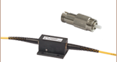
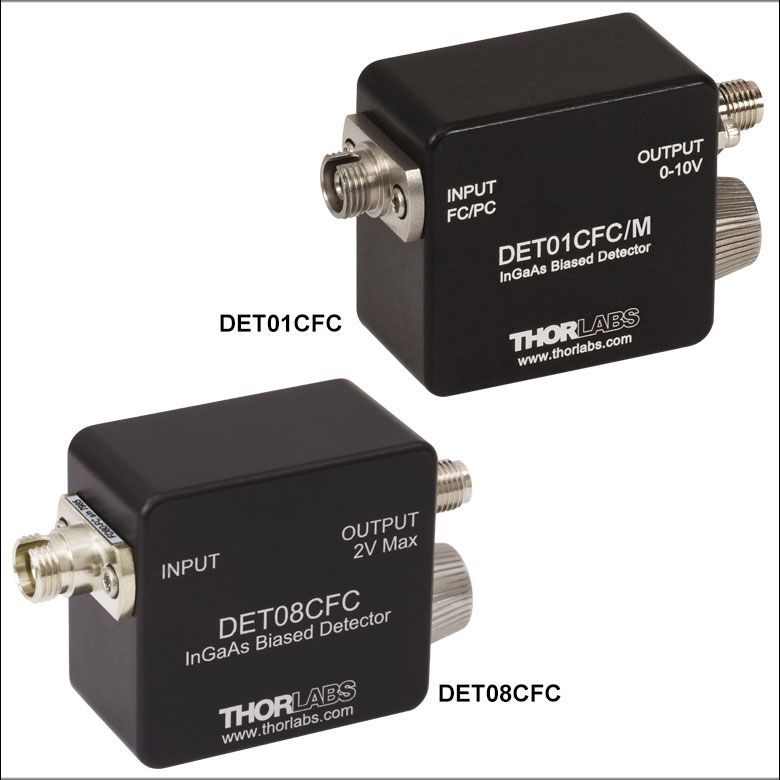
- DET01CFC: 1.2 GHz Bandwidth, <1 ns Rise Time
- DET08CFC: 5 GHz Bandwidth, 70 ps Rise Time
The DET01CFC(/M) is designed for use in the 800 - 1700 nm spectral range. It uses an InGaAs detector element based on our FGA01FC photodiode and features a 1.2 GHz bandwidth. It has an FC/PC input connector, and our testing shows that it can also be used with FC/APC patch cables with no measurable differences in performance. An 8-32 tapped mounting hole (M4 for the metric version) allows easy mounting to our series of Ø1/2" posts.
The DET08CFC(/M) is designed for use in the 800 - 1700 nm spectral range. It uses an InGaAs detector element and features a 5 GHz bandwidth. It has an FC/PC input connector, and our testing shows that it can also be used with FC/APC patch cables with no measurable differences in performance. An 8-32 tapped mounting hole (M4 for the metric version) allows easy mounting to our Ø1/2" posts.
| Item # | Wavelength | Detector | Bandwidth | Max Peak Power | Rise Time | Fall Time |
|---|---|---|---|---|---|---|
| DET01CFC | 800 - 1700 nm | InGaAs | 1.2 GHz | 18 mW | <1 nsa | <1 nsa |
| DET08CFC | 800 - 1700 nm | InGaAs | 5 GHz | 100 mW | 70 ps (Typ.) | 110 ps (Typ.) |

 Zoom
Zoom
Click to Enlarge
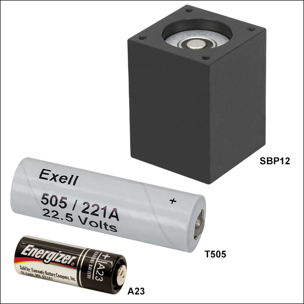
Exploded View of SBP12 Battery Pack
- A23: For Currently Shipping DET Photodetectors
- SBP12: For Discontinued SV2-FC and SIR5-FC Fiber-Coupled Photodetectors
- T505: For Discontinued DET1-SI and DET2-SI Detectors
A23 and T505 Alkaline Batteries
The A23 and T505 are replacement alkaline batteries for Thorlabs' currently shipping and discontinued DET photodetectors. For cases where the finite lifetime of a battery is not acceptable, we also offer an AC power adapter; please see below for more information. Information on expected battery lifetime is in the Battery Lifetime tab above.
SBP12 Battery Pack
The SBP12 is a 12 V replacement alkaline battery pack for our SV2-FC and SIR5-FC fiber-coupled photodetectors. It completely replaces the 20 V battery that was originally used (Item # SBP20), which we can no longer offer due to shipping regulations. Our testing shows that a 12 V bias provides performance similar to a 20 V bias, and the performance is within the detectors' stated specifications.
As shown by the photo to the right, the SBP12 consists of an A23 battery in a newly designed housing. You may already own this housing if you purchased your SV2-FC or SIR5-FC in or after October 2013, or if you have already purchased an SBP12. If you do own this housing, then it is necessary to purchase only the A23 battery.
Customers who own an SV2-FC or SIR5-FC detector purchased before October 2013 will need to bend two pins to ensure that the SBP12 battery pack makes electrical contact. The procedure is illustrated in the spec sheet of the battery, which can be downloaded here.

 Zoom
Zoom- DET2A: Power Adapter for DET Series Detectors
- LDS12B: ±12 VDC Power Supply
- DET2B: Bundle of the DET2A and LDS12B
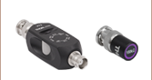
DET2A Power Adapter
The DET2A is a power adapter for our DET series detectors. This power adapter will directly replace the A23 battery and spring-loaded cap to allow the detector to run directly from our LDS12B power supply (sold separately). The DET2A is also compatible with the PDA-C-72 power supply cable for custom connections. Note that when connecting the DET2A and the PDA-C-72 to power DET series detectors, only the brown (+12 V) and black (GND) pins are needed.
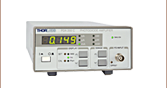
LDS12B Power Supply
The LDS12B is a ±12 VDC regulated power supply, which incorporates a current limit, enabling short circuit and overload protection; an on/off switch with an LED indicator; and a switchable AC input voltage (100, 120, or
230 VAC). A region-specific power cord is shipped with the LDS12B power supply based on your location.
DET2B Power Adapter Bundle
The DET2B power adapter bundle includes both the DET2A power adapter and the LDS12B power supply. This power adapter bundle can be used to replace the battery in our DET series detectors. To use the DET2B, simply replace the battery and spring-loaded cap with the included DET2A adapter, insert the three pin plug from the LDS12B power supply into the adapter, and screw the adapter into the detector. This procedure is depicted in the animation to the above right.