Manual Drive, 1" Digital Micrometer

- 1 µm Resolution
- Instant Inch/Millimeter Conversion
- Spherical Face Spindle
Application Idea
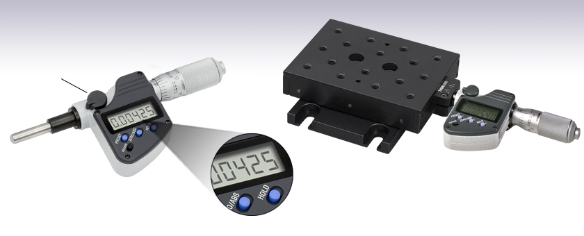
PT1 Translation Stage Preinstalled with DM713 Digital Micrometer,
Mounted onto PT101 Base Plate
DM713
Lock
Knob

Please Wait

Features
- 1 µm Resolution
- Accuracy (Excludes Quantization Errors): ±2 µm
- Travel Range: 1" (25.4 mm)
- Instant Inch to Millimeter Conversion
- Measurement Hold Key and Micrometer Lock Knob
- Zero-Set Key Allows for Setting Zero Measurement at any Point Along the Spindle Travel
- Each Unit Comes Complete with a SR44 Battery, Key Spanner, and Operation Manual
- Battery Life is 1 Year with Normal Use
- Spherical Face Spindle
- Automatic Power-Off
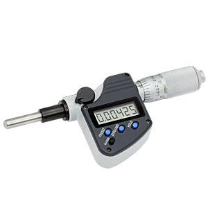
The DM713 Digital Micrometer features a 1" (25.4 mm) travel range and offers an inch/millimeter readout with 1 µm resolution. The digital actuator also offers relative position and hold measurement functions, and the 3/8" (9.5 mm) mounting barrel is compatible with our 1" (25 mm) travel ball bearing translation stages. To order one of these stages preconfigured with the DM713 micrometer, please contact Technical Support.
Insights into Motion Control Using the DM713 Digital Micrometer
Scroll down to read about:
- Recording Position from Digital Micrometers
- DM713 Digital Micrometer: LabVIEW and C# Programming References
Click here for more insights into lab practices and equipment.
Recording Position from Digital Micrometers

Click to Enlarge
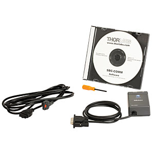
Figure 2: The SBC-COMM package shown above can be used to log data position data displayed by the DM713 digital micrometer.

Click to Enlarge
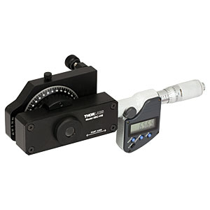
Figure 1: The DM713 digital micrometer (right) is included with and used to adjust the retardance provided by the
Digital micrometers, such as the DM713, are handy for moving a piece of optomech a specific distance. For example, a user might want to increment a translation stage holding a sample in front of an objective lens in order to focus the light to equally spaced points within the sample.
However, there are also times where the user might want to record the position of an event. One example could be making a distance measurement where the micrometer is set to a starting position, zeroed, and then translated the desired amount to display the distance.
Using the DM713 alone creates an extra step where the user has to read and record the display, which can be tedious in a dark lab where the display is not visible. One solution is to use Thorlabs' SBC-COMM, which includes an RS-232 interfacing cable. Thorlabs has created software application notes that walk the user through creating Visual C#® and LabVIEW® programs to continuously measure distances with the DM713. The application notes can be downloaded from links in the following section.
Another solution is to purchase the Mitutoyo® 05CZA662 SPC cable and IT-016U USB input tool that provide a push button and USB interfacing cable. With this device the user can open any text entry software package, press the single push button, and the device acts like a keyboard to enter the number into the software.
Date of Last Edit: Dec. 4, 2019
DM713 Digital Micrometer: LabVIEW and C# Programming References

Click to Enlarge
Figure 3: Visual C# and LabVIEW programs can be written to interrogate the DM713 Digital Micrometer. Examples are detailed in programming references available for download.
Programming references that provide introductions to communicating with the DM713 Digital Micrometer (Figure 3) are available. One reference has been developed for LabVIEW, and the other for Visual C#. Each reference includes a step-by-step discussion for writing the program, as well as a section that concisely provide the full program text without explanation.
Included in the LabVIEW Programming Reference:
- Instructions for downloading and installing the driver software.
- Information concerning the required cabling and connecting to the DM713's COM port.
- Creation of a new VI that establishes serial communications with the DM713.
- Data from the DM713 is continuously received.
- The displacement value and its units of measurement are displayed.
- Logging a data value in response to a button click is implemented.
Included in the Visual C# Programming Reference:
- Information for connecting the computer to the DM713's COM port.
- Instructions for spawning a secondary thread to continuously communicate with the DM713.
- Procedure for operating on the received data, to extract the displacement value and units.
- Instructions for displaying the displacement values and units in the program's GUI.
- Logging a displacement value to a file in response to a button click.
Date of Last Edit: Dec. 4, 2019
| Posted Comments: | |
Marty Johnston
(posted 2019-09-26 08:31:17.23) Hello,
You should offer the USB connection cord for this micrometer head. It allows you to input the reading directly into any text cell on a computer without any additional hardware. The computer treats the micrometer head like a "keyboard". It's very handy.
Regards
Marty YLohia
(posted 2019-09-27 12:23:31.0) Hello Marty, thank you for your feedback. I have posted your request on our internal product engineering forum to be considered for a future product release. user
(posted 2019-09-19 09:58:24.923) Dear Mr/Mrs,
I would like to ask whether the manual vernier scale is metric or imperial?
Best regards,
Henk-Jan YLohia
(posted 2019-09-20 09:51:55.0) Hello Henk-Jan, thank you for contacting Thorlabs. The graduation marks are imperial on the DM713. mathieu.gentile
(posted 2017-03-09 10:46:34.623) Hello,
with 10.9mm radius the DM713 is too large to be compatible with a PT1(/M) as suggested in the application idea illustration. When a PT1/M is directly screwed on a table, the axis of the micrometer is 9.7mm above the table plane.
That's a frustrating 1.2mm clearance issue...
Best regards
MG jlow
(posted 2017-03-09 09:44:23.0) Response from Jeremy at Thorlabs: To make this compatible, one would need to add the PT101 base plate to the assembly. I will get the application idea picture updated to show the assembly with the base plate. mnmn1r11
(posted 2016-03-02 13:12:26.613) It is stated that the DM713 has a 1um resolution, but the accuracy is +-2um. Is this correct? I do not understand how could the step resolution be smaller than the accuracy of the device.
Also, how complicated it would be to swap the standard PT1 translation stage micrometer head with DM713? besembeson
(posted 2016-03-02 02:19:11.0) Response from Bweh at Thorlabs USA: Yes that is correct. The resolution relates to the smallest increment the actuator can be commanded to move based on the encoder and display. Due to friction, inertia and other motion control constraints, the actual displacement will be higher than this value, which makes the accuracy to be bigger. You can directly release the screw that locks the barrel of the standard micrometer and replace it with the DM713. hambitza
(posted 2013-06-25 10:01:06.473) I have two question regarding the DM713:
* what is the load capacity (N) in the translation direction
* can the device be interfaced to a computer, e.g. via Labview? pbui
(posted 2013-06-27 14:38:00.0) Response from Phong at Thorlabs: The maximum load capacity for the DM713 varies according to the type of the load applied (static load or active load) and operating conditions (used as a feeding device or stopper). When used as a measuring device, the rated accuracy spec for the DM713 is guaranteed for load limits not exceeding 4 kg.
There is a device that you can use to connect the DM713 to a computer to log measurement data. Since Thorlabs does not support the device, I would recommend you contact Mitutoyo directly regarding their USB Input Tools, USB-ITN. tor
(posted 2011-01-10 15:29:59.0) Response from Tor at Thorlabs to cbrideau: Thank you for your request. I will contact you directly to determine whether we can provide this as a custom item. cbrideau
(posted 2010-12-14 19:22:51.0) Would it be possible to get a 2" travel version of this for use with the LNR50 TravelMax stage? apalmentieri
(posted 2010-01-20 14:54:44.0) A response from Adam at Thorlabs: The DM713 is initially set up to give an absolute position. Although this is the inital setup, the user has the option of setting the zero point at any point along the travel of the micrometer to get a relative position based of your desired zero position. To set the zero position, all one has to do is move the micrometer to a position and press the zero button. user
(posted 2010-01-20 14:07:34.0) Can this give an absolute position or are all measurements relative to the position where the user last pressed the zero button? Tyler
(posted 2008-07-03 17:26:42.0) A response from Tyler at Thorlabs to Tim: The drawing files you have requested are available under the "Drawings and Documents" tab. If you have any issues with the file formats available or in downloading the drawings please repost. Thank you for you interest in our products. tim.marti
(posted 2008-07-03 16:08:30.0) Do you have 3D models of your part no. DM713? If so, could you please email a 3D STEP file or a SolidWorks 3D model of the part?
Thanks,
Tim Marti TechnicalMarketing
(posted 2007-10-16 14:41:20.0) Thank you for pointing out that the presentation was missing the accuracy specification; it has now been added to the "Overview" tab. We are continually working to improve the content of our web pages in order to serve our customers and the value of user feedback in this effort is immense. acable
(posted 2007-08-27 15:36:42.0) What is the accuracy of this device. Also the Soleil-Babinet compensator has an interface kit that works with the DM713, it would make sense to offer that with this device as well as the 1" micrometer that is also offered that appears to use the same electronics. acable
(posted 2007-08-27 15:06:52.0) In the Related Products area you show the "1/4"-80 Adjustment Screws", please consider changing to "Fine Adjustment Screws" since this link takes the viewer to a page with all the adjustment screws (which BTW is very useful). |
 Products Home


 1" (25.4 mm) Travel, Digital Micrometer