 Products Home / Fiber Components / Fiber Optic Attenuators / Electronic Variable Optical Attenuators, Voltage Controlled & SM Fiber Coupled
Electronic Variable Optical Attenuators, Voltage Controlled & SM Fiber Coupled
- MEMS-Based Control of Optical Power in Single Mode Fiber
- Six Models Cover Wavelengths from 450 nm to 2300 nm
- Optical Attenuation up to >30 dB or >25 dB
- Modulation up to 1 kHz
- MEMS-Based Electronic Control of Optical Power in Fiber
- Five Models Cover Wavelengths from 450 nm to 1650 nm
- DC to 1 kHz Bandwidth
- Maximum Attenuation >20 dB or >30 dB
V1550A
Electronic VOA, FC/APC Version
(1250 nm - 1650 nm Model)
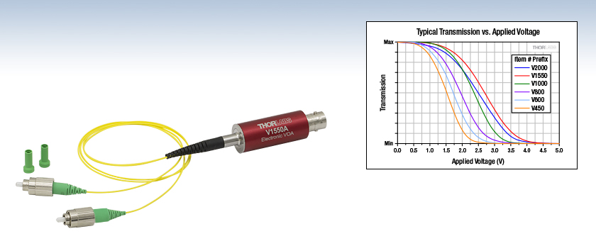
Typical transmission as a function of applied voltage for all models, which are offered with FC/PC or FC/APC connectors.


Please Wait
| Quick Links | |||
|---|---|---|---|
| Item # Prefix | Wavelength Range | Max Attenuation |
Connector Options |
| V450 | 450 - 600 nm | >30 dB | FC/APC or FC/PC |
| V600 | 600 - 780 nm | ||
| V800 | 780 - 980 nm | ||
| V1000 | 980 - 1250 nm | ||
| V1550 | 1250 - 1650 nm | >25 dB | |
| V2000 | 1700 - 2300 nm | ||
| Fiber Optic Attenuator Selection Guide | |
|---|---|
| SM |
Electronic VOAs for System Integration |
| Tabletop EVOAs with Power Lock | |
| Manually Variable Attenuators | |
| Fixed-Value Attenuators | |
| MM | Fixed-Value Attenuators |
| Manually Variable Attenuators | |
| PM |
Electronic VOAs for System Integration |
| Manually Variable Attenuators | |

Click to Enlarge
A female BNC connector is located on one end of the barrel, and fiber leads with either FC/APC or FC/PC connectors are integrated into the opposite end. Each barrel is engraved with the shown information for convenience.
Features
- MEMS-Based Devices Provide Attenuation up to >30 dB or >25 dB (See Table to the Right)
- Single Mode Operation
- Control Optical Power by Applying 0 to 5 V Signal
- Six Operating Wavelength Ranges Available (See Table to the Right)
- Maximum Optical Input Power of 100 mW
- Modulation up to 1 kHz
- BNC Input is Protected from Electrostatic Discharge
Thorlabs' Fiber-Coupled Electronic Variable Optical Attenuators (VOAs) are microelectromechanical system (MEMS) based devices that provide attenuation up to >30 dB or >25 dB, depending on the model. The optical fiber built into each device is single mode over the specified operating wavelength range. Driving voltages of 0 to 5 V control optical transmission, which decreases with applied voltage. These high-speed VOAs support modulation up to 1 kHz. Protection diodes integrated into the design limit the input voltage to protect the VOA from ESD, as well as from other over-voltage and under-voltage events.
A plot of the typical relationship between the applied voltage and the optical transmission for each electronic VOA model is included in the Specs tab. Most voltage sources, including power supplies, function generators, and digital-to-analog converters (DACs), can be used to control these electronic VOAs. Use a BNC cable (not included) to connect the electronic VOA to the voltage source. The MEMS VOA is an electrostatic device that inherently requires no current. However, the protection circuitry can draw up to 100 µA for applied voltages of 5 V.
Either of the unit's 50 cm long fiber leads can be used as the input, as performance is similar in both directions. However, you may find that one of the connectors provides a lower loss connection in your set-up due to the random nature of core alignment. As shown in the image above, the barrel of each electronic VOA is etched, for convenience, with information such as the operating wavelength range, maximum optical input power, maximum modulation bandwidth, and driving voltage range. These VOAs are designed for use with optical fiber that is single mode within the operating range. Please see the Specs tab for information on the single mode fibers integrated into each model.
Electronic VOAs with polarization-maintaining (PM) fiber and FC/APC connectors are available here.
Fiber Core Alignment
Note that the minimum attenuation for these devices depends on excellent core-to-core alignment when the connectors are mated. This is even more crucial for shorter wavelength VOAs with smaller fiber core diameters. If they are not perfectly aligned, the insertion loss can easily go up many decibels above the specification. Since we cannot control the fibers that are used to connect to these devices, we test the devices for minimum attenuation by using a setup that actively aligns the cores of the fibers and minimizes the connector loss. From this, we obtain the minimum attenuation possible for each device. Unless the user also does the same, or better yet, fusion splices the fibers, they may not achieve the specified minimum attenuation.
| Item # | V450A | V450F | V600A | V600F | V800A | V800F | V1000A | V1000F | V1550A | V1550F | V2000A | V2000F | |
|---|---|---|---|---|---|---|---|---|---|---|---|---|---|
| Wavelength Range | 450 to 600 nm | 600 to 780 nm | 780 to 980 nm | 980 to 1250 nm | 1250 to 1650 nm | 1700 to 2300 nm | |||||||
| Attenuationa | Max | >30 dB | >25 dB | ||||||||||
| Min | 2.5 dB | 2.0 dB | 1.5 dB | ||||||||||
| Optical Input Power | 100 mW Max | ||||||||||||
| Optical Return Loss | >30 dB | ||||||||||||
| Fiber Connectorsb | FC/APC | FC/PC | FC/APC | FC/PC | FC/APC | FC/PC | FC/APC | FC/PC | FC/APC | FC/PC | FC/APC | FC/PC | |
| Device Fiber Typec | 460HP | 630HP | 780HP | HI1060-J9 | SMF-28 Type | SM2000 | |||||||
| Modulation Signal Input | |||||||||||||
| Input Voltage | 0 to 5 V (Absolute Max: 10 V, 5 mA) | ||||||||||||
| Input Impedance | High-Z | ||||||||||||
| Bandwidth | DC to 1 kHz | ||||||||||||
| Input Voltage Connector | Female BNC | ||||||||||||
| Physical Specifications | |||||||||||||
| Dimensions | Diameter: 15.7 mm (0.62") Length Excluding Fiber Leads: 50.1 mm (1.97") Length of the Fiber Leads: 50.0 cm ± 10.0 cm |
||||||||||||
| Operating Temperature | 0 °C to 40 °C | ||||||||||||
| Storage Temperature | -20 °C to 70 °C | ||||||||||||
| Relative Humidity | 5% to 85% (Non-Condensing) | ||||||||||||

Click to Enlarge
Typical Optical Transmission as a Function of Applied Voltage
(Test Wavelengths: 520 nm for V450 models; 635 nm for V600 models; 850 nm for V800 models; 1060 nm for V1000 models;
1550 nm for V1550 models; 2000 nm for V2000 models)

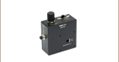
Click to Enlarge
The supply current required to drive these electronic VOAs over the 0 to 5 V operating range is plotted above.

Click for Details
Mechanical Drawing of the Fiber-Coupled VOA Package
| Posted Comments: | |
alexey.kokhanovskiy
(posted 2018-09-12 12:58:11.63) Hello,
Could you provide information about PM version of electronic variable optical attenuators V1000A and V1550A. Is it possible to make V1000A with PM980 fiber?
With respect,
Alexey Kokhanovskiy YLohia
(posted 2018-09-18 09:16:43.0) Hello Alexey, we already manufacture a PM version of the V1000A -- the part number for this is V1000PA and it contains PM980-XP fibers. hmcgui
(posted 2017-06-27 14:32:33.16) I am also interested in a PM version. Please let me know when one will be available. tfrisch
(posted 2017-08-03 11:58:37.0) Hello, thank you for contacting Thorlabs. PM versions of these VOAs have been submitted for release as stock items, and I expect they will be available soon. I will reach out to you with more details. massey4
(posted 2017-06-02 07:15:04.803) Is there a PDF manual for the device or only the spec sheet?
What is the absolute maximum allowed applied voltage? nbayconich
(posted 2017-06-15 01:42:54.0) Thank you for contacting Thorlabs. The suggested applied voltage for these variable optical attenuators is 5V (1 mA. These VOA's can be operated up to 10V. There is a shunting circuit between the BNC connector and the MEMS VOA so this can be used at 10 Volts without damaging the circuit.
Currently we have a brief operating guide in the .pdf spec sheet available to download. To operate the VOA connect the optical input and output to the respective fiber leads on the unit. Either of the unit’s fiber leads can be used as the input, as performance is similar in both directions. Use a BNC cable to connect a power supply or other voltage source to the unit, and then apply 0 to 5 V to control the attenuation. Optical transmission decreases with applied voltage. A techsupport representative will contact you directly. f.m.j.cozijn
(posted 2017-05-12 11:56:34.4) This is an excellent product and I would order one right away if it was a PM version. Is there a PM version planned in the near future? tfrisch
(posted 2017-05-17 04:34:12.0) Hello, thank you for contacting Thorlabs. I will reach out to you directly about availability of PM versions. parkse
(posted 2017-04-17 22:19:14.997) Please produce VOS for PM fiber. tfrisch
(posted 2017-04-28 03:26:20.0) Hello, thank you for contacting Thorlabs. I have posted your request in our internal engineering forum. I agree that this would be a useful extension of this product line. |
- Attenuation Range: 2.5 dB to >30 dB
- Maximum Optical Input Power of 100 mW
- Integrated 460HP Single Mode Fiber Pigtails with FC/APC or FC/PC Connectors
The V450A and V450F are fabricated with and designed for use with optical fiber that is single mode within its operating range. An example of compatible single mode optical fiber is 460HP. Please note that minimum attenuation is highly dependent on connector alignment, especially at shorter wavelengths. Given specifications assume good core-to-core alignment at the connector.
- Attenuation Range: 2.5 dB to >30 dB
- Maximum Optical Input Power of 100 mW
- Integrated 630HP Single Mode Fiber Pigtails with FC/APC or FC/PC Connectors
The V600A and V600F are fabricated with and designed for use with optical fiber that is single mode within its operating range. An example of compatible single mode optical fiber is 630HP. Please note that minimum attenuation is highly dependent on connector alignment, especially at shorter wavelengths. Given specifications assume good core-to-core alignment at the connector.
- Attenuation Range: 2.0 dB to >30 dB
- Maximum Optical Input Power of 100 mW
- Integrated 780HP Single Mode Fiber Pigtails with FC/APC or FC/PC Connectors
The V800A and V800F are fabricated with and designed for use with optical fiber that is single mode within its operating range. An example of compatible single mode optical fiber is 780HP. Given specifications assume good core-to-core alignment at the connector. Please note that minimum attenuation is highly dependent on connector alignment.
- Attenuation Range: 2.0 dB to >30 dB
- Maximum Optical Input Power of 100 mW
- Integrated HI1060-J9 Single Mode Fiber Pigtails with FC/APC or FC/PC Connectors
The V1000A and V1000F are fabricated with and designed for use with optical fiber that is single mode within its operating range. An example of compatible single mode optical fiber is HI1060-J9. Given specifications assume good core-to-core alignment at the connector. Please note that minimum attenuation is highly dependent on connector alignment.
- Attenuation Range: 1.5 dB to >25 dB
- Maximum Optical Input Power of 100 mW
- Integrated SMF-28 Type Single Mode Fiber Pigtails with FC/APC or FC/PC Connectors
The V1550A and V1550F are fabricated with and designed for use with optical fiber that is single mode within its operating range. An example of compatible single mode optical fiber is SMF-28 Ultra. Given specifications assume good core-to-core alignment at the connector. Please note that minimum attenuation is highly dependent on connector alignment.
- Attenuation Range: 1.5 dB to >25 dB
- Maximum Optical Input Power of 100 mW
- Integrated SM2000 Single Mode Fiber Pigtails with FC/APC or FC/PC Connectors
The V2000A and V2000F are fabricated with and designed for use with optical fiber that is single mode within its operating range. An example of compatible single mode optical fiber is SM2000. Given specifications assume good core-to-core alignment at the connector. Please note that minimum attenuation is highly dependent on connector alignment.